1
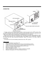
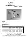
Owner’s Manual
150 Watt
Tungsten Halogen
Light Source
CSA Listed to UL-1571
LIGHT SOURCE MODELS
115 VAC/60Hz
230 VAC/50Hz/60Hz
A20500
SOLID STATE RHEOSTAT A20500.1
A20500.2
EKE Lamp
EJA Lamp
DDL Lamp
A20510
A20510.1
A20510.2
EKE Lamp
EJA Lamp
DDL Lamp
A20520
SOLID STATE RHEOSTAT
A20520.1
AND IRIS DIAPHRAGM
A20520.2
EKE Lamp
EJA Lamp
DDL Lamp
A20530
A20530.1
A20530.2
EKE Lamp
EJA Lamp
DDL Lamp
122 Charlton Street, Southbridge, MA 01550-1960
Phone: (508) 765-9744, Fax: (508) 765-1299
Email: [email protected] www.us.schott.com/lightingimaging
CONGRATULATIONS on the purchase of your “ACE” light source! This light source
provides COOL, INTENSE WHITE light for all types of fiber optic illumination components and
either meets or exceeds the performance standards of all the safety certification agencies like UL,
ETL, CSA, and VDE. It was de-signed and is manufactured under the ISO 9000 guidelines.
The “ACE” light source provides a variable powered output of up to 150 watts of light from a
tungsten halogen lamp. The voltage-adjustable supply provides ≈1.0 to 21 VAC at 60 Hz. Lamp
®
intensity is controlled manually from the front panel. The removable Modulamp assembly
contains the lampholder which supports three different bulb choices depending on intensity,
lifetime and uniformity requirements. The high output fan provides maximum airflow resulting in
extremely cool operation.
We suggest you read this manual carefully to become familiar with all the light source features
and how they work.
MAINTENANCE
Although your light source is designed to be maintenance free, it does contain sensitive
electronic parts. TREAT IT WITH CARE TO ASSURE BEST PERFORMANCE. The original
packaging should be used for protection, if you must ship the system.
CLEANING
The steel housing and the Lexan front and back plates have a durable finish that should retain
their original luster for many years. Clean exposed parts with any commercial glass cleaner. DO
NOT USE detergents, excess water, treated cloths, harsh cleaning agents or sprays. Use
cleaning fluid SPARINGLY. If you spill fluid into the interior, unplug the power cord and let the unit
dry thoroughly before using.
WARNING:
This product produces heat as a normal part of its operation. Hot lamp and internal surfaces can
cause burns. Operators are advised to allow the unit to cool before opening or relamping
“Modulamp” assembly.
OPERATION
To begin, make sure the intensity control switch on the front panel is in the “OFF” position. Plug
one end of the power cord into the IEC connector on the back of the unit and the other end into a
power source which meets the specifications printed above the IEC connector.
Make sure that the captive thumbscrew on the “Modulamp” assembly is firmly tightened. Insert
any fiber optic component with a compatible light source adapter into the “Modulamp” receptacle
and tighten the fiber optic positioning thumbscrew. Adjust the intensity of the lamp using the
control knob.
To turn the unit off, turn the intensity control knob to the “OFF” position.
OPERATIONS
1
Mettre l'interrupteur sur position “off”.
2
Connecter le cordon d’alimentation à la source et le brancher au secteur.
3
Vérifier que la vis sur la face avant du module lampe soit fermement visée.
4
Insérer le conducteur fibre optique à l’intérieur de la source.
5
Serrer pour maintenir la fibre en place.
6
Mettre l’interrupteur sur “ON’.
7
Ajuster l’intensité de la lampe en utilsant le rhéostat de contrôle.
8
Remettre l’interrupteur sur “off” pour éteindre la source.
FUNCIONAMIENTO
1
Interruptor apagado.
2
Enchufar en el conectador IEC.
3
Enchufar en un enchufe conforme a las especificaciones encima del conectador IEC.
4
Apretar el tornillo en el aparato “Modulámpara”.
5
Insertar la parte constituliva fibra-óptica compatible en el ajustador del origen de luz.
6
Apretar el tornillo que retiene la fibra-óptica.
7
Interruptor encendido.
8
Ajustar la intensidad de la lámpara con la perilla (el botón).
9
Apagar la luz.
INBETRIEBNAHME DER KALTLICHTQUELLE
1
Netzscalter in die “OFF”-Stellung bringen.
2
Netzkabel in die Buchse auf der Rückseite der Kaltlichtquelle stecken.
3
Netzkabel mit der Spannungsquelle verbinden. Die Spannungsquelle muß die über der
Netzkabelbuchse unter “Input” angegebene Spannung und Netzfrequenz liefern.
4
Feststellschraube des Lampeneinschubes fest anziehen.
5
Kompatibles Faserbündel in den Faserbündeladapter der Lichtquelle einführen.
6
Feststellschraube des Faserbündeladapters anziehen.
7
Netzschalter in “ON”-Stellung bringen.
8
Intensität der Lampe mit Kontrollpotentiometer auf gewünschten Wert einstellen.
9
Zum Abschalten der Lichtquelle den Netzschalter in “OFF”-Stellung bringen.
FUNZIONAMENTO
1
Pulsante di potenza in posizione OFF.
2
Innestare il cavo nel connettore IEC sul retro dell’elemento.
3
Innestare il cavo nella sorgente eletrica secondo le instruzioni sopra il connettore IEC.
4
Avvitare fermamente la vite nel montaggio della modulampada.
5
Inserire il componente compatible Fibra Ottica nel dispositivo elettrico.
6
Avvitare la vite per mantenere ferma la Fibra Ottica.
7
Pulsante di potenza in posizione ON.
8
Regolare l’intensitá della lampadina usando la manopola di controllo.
9
Pulsante a OFF per spegnere la sorgente di luce.
LAMP REPLACEMENT
•
•
•
•
•
•
•
•
•
Turn power off.
Remove the fiber optic component.
Allow the lamp to cool.
Loosen the “Modulamp” captive thumbscrew until the head springs forward.
Pull the top of the “Modulamp” assembly forward and lift the unit out of the recess.
CAUTION: LAMP, LAMP SOCKET AND SURROUNDING SURFACES MAY BE HOT!
Do not pull the Assembly beyond the length of the cable and connector assembly. You can
remove the “Modulamp” assembly, if you desire. Instructions follow.*
Push down on the lampholder release lever to raise the lamp.
Gently unplug the ceramic lamp socket.
Insert a new bulb into the lamp socket. BE CAREFUL NOT TO TOUCH THE BULB OR THE
INSIDE OF THE REFLECTOR. FINGER-PRINTS MAY AFFECT THE LAMP OUTPUT.
Push the ceramic socket on the two lamp pins until flush with the reflector.
LIFT
CAPTIVE THUMBSCREW
TO REMOVE THE “MODULAMP”
ASSEMBLY:
• Make sure the power switch is off.
• Reach into the recess and depress the
release tab on the connector.
• Slide the connector apart and remove
the “Modulamp” assembly.
TO REPLACE THE “MODULAMP” ASSEMBLY:
• Slide the connector into the mating receptacle until the release tab clicks into place.
• Place the “Modulamp” assembly into the recess with the two bottom “ears” riding over the
bottom edge of the recess first.
• Slide the “Modulamp” assembly into place and depress the captive thumbscrew while turning
clockwise. TIGHTEN FIRMLY.
TO CHANGE BULB TYPES
• The “Modulamp” concept allows quick change of bulb, bulb type and/ or intensity control (Iris
diaphragm or solid state rheostat) by exchanging “Modulamp” assemblies. However the bulb
settings may be changed by moving the lamp holder into the correct position. Consult the
factory for correct lamp locations.
REMPLACEMENT DE LA LAMPE
1 Mettre l’interrupteur sur position “off”.
2 Retirer le conducteur fibre optique.
3 Laisser la lampe refroidir.
4 Dévisser le module lampe avec un petit tournevis jusqu’à ce que la tête ”s’éjecte par devant”
5 Tirer l’ensemble du module lampe et l’enlever de son logement. Ne pas tirer l’ensemble plus
loin que la longueur de câble.
6 Appuyer sur le porte lampe pour retirer la lampe.
7 Défaire doucement la base en céramique de la lampe.
8 Insérer la nouvelle lampe dans la base. Ne pas toucher le bulbe ou l’intérierur du réflecteur.
9 Pousser la base en céramique de la lampe jusqu’à ce qu’il y ait contact avec la base.
PARA REEMPLAZAR LA LÁMPARA (la bombilla)
1
Apagar el aparato.
2
Separar la parte fibra-óptica.
3
La lámpara debe estar fresca.
4
Desatar el tornillo de la “Modulámpara” hasta que la cima se abalanza hacia adelante.
5
Tirar la cima del la lámpara y levantar del hueco. No tirar más allá el largo del cable.
6
Empujar la palanca para quitar la lámpara.
7
Deshacer el enchufe (encaje) cerámico.
8
Insertar la nueva lámpara. No tocar la bombilla. No tacar el interior del reflector.
9
Empujar en la lámpara el enchufe cerámico.
10
Deslizar la “Modulámpara” en las “orejas” del origen de luz (por encima del borde del
fondo, al principio). 11.Apretar el tornillo.
LAMPENWECHSEL
1
Nettzschalter in “OFF”-Stellung bringen.
2
Faserbündeladapter herausziehen.
3
Lampe abkühlen lassen.
4
Feststellschraube des Lampenienschubes so lange lösen, bis die Einschubkassette
herausspringt.
5
An der Oberseite des Lampeneinschubes ziehen und die Kassette über die Vorderkante
der Einschuböffnung der Lichtquelle herausheben. Niemals den Lampenieinschub so weit
herausziehen, daß die Länge des Lampenkabels überschritten wird.
6
Durch Herunterziehen des Hebels die Lampe nach oben drücken und Lampe vorsichtig
herausnehmen.
7
Lampe vorsichtig aus Keramiksockel herausziehen.
8
Neue Lampe in Keramikosockel einstecken. Niemals die Halogenbirne oder das Innere des
Reflektors berühren!
9
Die Lampe in den Lampeneinschub einsetzen; die Lampe muß dabei die Grundfläche
berühen.
10.
Lampeneinschub in Kaltlichtquelle wieder einsetzen. Die Einschubkassette auf die
Unterkante der Einschuböffnung setzen.
11.
Feststellschraube des Lampeneinschubes fest anziehen.
PER SOSTITUIRE LA LAMPADINA
1
Pulsante di potenza in posizione OFF.
2
Rimuovere il componente Fibra Ottica.
3
Lasciare raffreddare la lampadina.
4
Allentare la vite nella modulampada fino a quando la testa non scatta in avanti.
5
Tirare la parte superiore della modulampada e sollevaria dal recesso. NON rimuovere il
montaggio oltre la lunghezza del cavo.
6
Abbassare il dispositivo di sgancio del portalampada per rimuovere la lampadina.
7
8
Delicatamente staccare il portalampada in ceramica.
Inserire la nuova lampadina nel portalampada. NON toccare il bulbo o l’interno del
riflettore.
Spingere la lampadina nel portalampada in ceramica fino a livello di base.
9
WARNING
•
•
•
Never look directly at lamp when on.
Modulamp” assembly must be firmly in
place to operate
Lamp and surrounding surfaces may be
hot!
!
ATTENTION
• Ne pas regarder directement la lampe quand elle fonctionne.
• Le module lampe doit étre fermement en place pour étre opérationnel.
• La lampe et son logement peuveut étre chaud.
ATTENDER
• Nunca mirar directamente la lámpara cuando iluminada.
• La “Modulàmpara” debe estar bien en su sitio para funcionar.
• La lámpara y las superficies cerca de la lámpara pueden estar muy calientes.
WARNHINWEISE
• Niemals direkt in die Lampe blicken, wenn die Kaltlichtquelle eingeschaltet ist.
• Der Lampeneinschub (Modulamp) muß fest montiert sein, damit die Kaltlichtquelle
betrieben werden kann.
• Die Lampe und angrenzende Oberflächen können heiß sein!
PRECAUZIONI
• Mai guardare direttamente la lampadina quando é accessa.
• La modulampada deve essere fissata fermamente per funzionare.
• La lampadina e la superficie circostante possono essere surriscaldate.
SAFETY INSTRUCTIONS
1
2
3
4
5
6
7
8
9
READ, UNDERSTAND AND FOLLOW ALL INSTRUCTIONS in this manual.
KEEP all safety and operating instructions for future reference.
HEED ALL WARNINGS on the unit and in this manual.
DO NOT USE this unit near water or in any area with excessive moisture.
MOUNT on surface, platform or wall ONLY as recommended by the manufacturer.
DO NOT BLOCK ventilation openings in this unit. It may cause overheating. Be sure that the
unit is NOT resting on or against any material or object that may IMPEDE air flow.
DO NOT PLACE FLAMMABLE materials on or near the unit at any time. Keep unit AWAY
from other sources of HEAT. ALLOW BULB TO COOL before attempting to replace.
USE THE CORRECT POWER SOURCE as marked on the unit.
DO NOT DEFEAT the safety purpose of 3-pronged grounding plug.
10
11
12
13
14
15
16
17
USE ONLY APPROVED POWER CORD supplied with the unit. Route cord so that it will not
be pinched, severed or walked on.
DO NOT DEFEAT THE PURPOSE OF THE FUSE. Replace only with fuse type described
in the operating instructions or as marked on the unit.
USE ONLY STANDARD GLASS TYPE CLEANERS. Do not use solvents, cleansers or
petroleum distillates. UNPLUG all cords before cleaning.
NEVER SPILL LIQUID ON THE UNIT OR PUSH OBJECTS INTO VENTILATION
OPENINGS. You may short out parts, resulting in risk of fire or electric shock.
DISCONNECT POWER CORD from outlet when unit will be left unused for a long period of
time.
DO NOT OPEN THIS UNIT. There are no user serviceable parts inside.
The unit should be serviced ONLY by SCHOTT authorized service personnel if it does not
operate normally or exhibits any marked change in performance; or if the power cord or
enclosure has been damaged; or if objects or moisture have entered the unit.
DO NOT SERVICE the unit beyond that described in this manual. All other servicing should
be referred to qualified service personnel.
TROUBLESHOOTING
If the fan operates, but there is no light, check the following in sequence.
1
2
3
4
Turn the Intensity Control knob to 100.
Change the bulb.
Examine lamp socket for damage. Check continuity of wiring. If contacts are carburized or
the ceramic base is cracked or the wiring is frayed, replace socket.
Make sure that the two pin modular connector is properly engaged in the locking position
(see lamp replacement section). Check contacts for proper operation.
If neither the lamp nor the fan operates, check the following in sequence.
1
2
3
4
Make sure the power cord is inserted completely into the IEC connector on the rear panel
and also into the correct power source.
Check power cord for damage.
Check fuse. Remove the power cord. Slide fuse drawer out and remove inner fuse. Check
for continuity. Replace with spare fuse if blown. REPLACE ONLY WITH FUSE TYPE
DESCRIBED ON REAR PANEL. Replace or reorder spare fuse.
If the unit feels warm, check for any obstruction to the air intakes or exhaust area. This light
source has an automatic reset, thermal cut-out device for safety protection. Let the unit
cool down for 10 minutes and turn it back on.
If the light source still doesn’t operate, refer to qualified SCHOTT authorized service
personnel. DO NOT ATTEMPT TO REPAIR THE LIGHT SOURCE!
SPECIFICATIONS
PHYSICAL:
ELECTRICAL:
Overall dimensions
Height:
4.62" (177 mm)
Width:
7.27" (185 mm)
Depth:
8.61" (219 mm)
Weight:
9 pounds
Input Voltage
115VAC/60Hz (Models A20500 & A20520)
230VAC/50Hz (Models A20510 & A20530)
Fiber Receptacle
.720" diameter (18.3 mm)
Environmental Operating
Temperature Range:
0° to 50°C Relative humidity Range:
0% to 95% non-condensing
Output
21VAC
Power Consumption
190 Watts (nominal)
Lamp Types –Tungsten Halogen
150 Watt, 21 Volt (EJA, EKE)
150 Watt, 20 Volt (DDL)
CSA to UL-1571,
Improvements may result in specification or feature changes without notice.
PARTS LIST
EJA Lamp
EKE Lamp
DDL Lamp
Lamp Socket
Assembly
Fiber Optic
Positioning
Screw
A08110
A08120
A08130
D08375-070
D08375-063
Rheostat Control Knob
Iris Control Knob
Fuse (10/pkg) 115 V units
Fuse (10/pkg) 220 V units
H09033-100
H09050-045
A08126
A08127
Power Cord
H09050-016
LIABILITIES
Any warranty implied under State Law shall be limited to one year from original delivery to original purchaser. Specifically
excluded from the manufacturer liability is damage resulting from acts of any deity, malicious mischief, vandalism, riots,
wars, improper installation or neglect in the operation or maintenance of the unit or misunderstanding of the properties of
the unit. Under no circumstances shall the manufacturer be obligated for consequential or other damages of any kind or
description, losses or expenses in connection with or by reason of the use of, or inability to use this unit for any reason. The
stated warranty provides the purchaser with specific legal rights, and there may be additional rights which vary from State to
State. Some States for example, do no allow exclusion of consequential damage.
SERVICE POLICY
Any service required for any reason must be performed by the manufacturer or an authorized service representative. All
service out-side the warranty will be performed upon the purchaser’s request according to normal service charges in effect
at the time. To return any item, an RMA# (Return Materials Authorization) from the manufacturer must be obtained. This
number must be affixed to the shipping label in plain sight. All shipping must be prepaid. The manufacturer guarantees all
repairs will be completed within two weeks. The manufacturer will return ship all units prepaid using carrier of choice. All
expedited shipping charges will be the responsibility of the purchaser.
D 20500.020 Rev. L – Jan. 2010
DCN # 14010