1
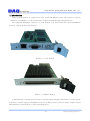
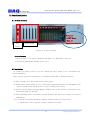
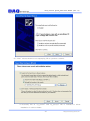
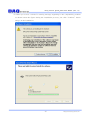
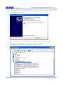
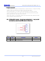
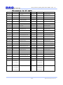
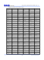
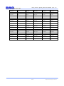
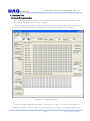
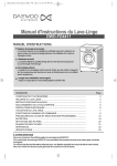
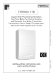
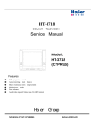
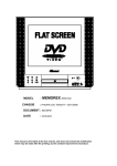
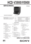
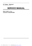
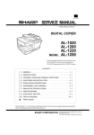
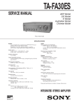
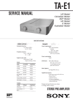
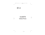
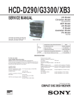
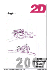
Relay Control System_4x50 Users Manual (Rev 1.0) Relay Control System (4x50) User’s Manual Windows, Windows2000, Windows NT and Windows XP are trademarks of Microsoft. We acknowledge that the trademarks or service names of all other organizations mentioned in this document as their own property. Information furnished by DAQ system is believed to be accurate and reliable. However, no responsibility is assumed by DAQ system for its use, nor for any infringements of patents or other rights of third parties which may result from its use. No license is granted by implication or otherwise under any patent or copyrights of DAQ system. The information in this document is subject to change without notice and no part of this document may be copied or reproduced without the prior written consent. Copyrights 2009 DAQ system, All rights reserved. -1- http://www.daqsystem.com Relay Control System_4x50 Users Manual (Rev 1.0) Contents 1. Introduction 2. Board Installation 2.1 Product Contents 2.2 Installation 3. Product Description 3.1 CPU Board Layout 3.2 Relay Board Layout 3.3 Function Description 3.3.1 CPU Board RJ45 connection 3.3.2 CPU Board D-sub 9 pin (male) connection – External Input trigger signal 3.3.3 Relay Board connection (4(Com) x 50(OUT)) And Relay Number 3.3.4 Relay Board Address Switch Setup 4. Function Test 4.1 Sample Program Interface 4.2 Function Description Appendix A.1 General Specification Reference -2- http://www.daqsystem.com Relay Control System_4x50 Users Manual (Rev 1.0) 1. Introduction Relay Control System is comprised of CPU board and RELAY board. The system is used to connect to a Backplane, it is an Output Relay Control System through using Local Bus. Be connected Backplane, [Figure 1-1] and [Figure 1-2] shows that CPU board and RELAY board is a safety product for industry. [Figure 1-1. CPU Board] [Figure 1-2. RELAY Board] A main function of board gets from user’s control signal through USB interface of CPU board, transmit to control signal to Backplane local bus of Relay board, control to Relay Output control through FPGA, external device control and inspection. -3- http://www.daqsystem.com Relay Control System_4x50 Users Manual (Rev 1.0) A general specification of board is as [Table 1.1 CPU Board]/[table 1.2 RELAY Board]. [Table 1.1 CPU Board] Physical Specification General Board Dimension 3U Compact-PCI Form-factor 2mm Hard-metric Compact PCI J1 connection 160 x 100 Euro-card standard Compact PCI connection USB 2.0 Interface Connection D-sub 9PIN External signal interface RJ45 External input(comA/comB only) Reserved Header Electrical specification 3.3V Operation General 1.2V DSP/FPGA core power, Max 6A 3.3V DSP PLL power Back plane Local bus interface Bus Interface +5V/+3.3V compatible operation TMS320C6713 – Digital Signal processor MPU(DSP) External FPGA Xilinx Spartan II XC3S200AN [Table 1.2 RELAY Board] Physical Specification General Board Dimension External Connection 3U Compact-PCI Form-factor 2mm Hard-metric Compact PCI J1 connection 160 x 100 Euro-card standard Compact PCI local connection MDR 100PIN RELAY OUTPUT Electrical Specification 3.3V Operation General 1.2V FPGA core power, Max 6A Back plane Local bus interface Bus Interface +5V/+3.3V compatible operation Xilinx Spartan II XC3S200AN FPGA -4- http://www.daqsystem.com Relay Control System_4x50 Users Manual (Rev 1.0) 2. Board Installation 2.1 Product contents Backplane. -1 CPU Board -Max. 15 CPU Relay Board Support Relay Board Board [Figure 2-1. Relay System] Product Contents 1. Relay System - CPU Board / Relay Board (Max. 15) / Backplane / Devices 2. CD (Driver/Manual/API/Sample source etc..) 2.2 Installation To install your Relay board in your PC, follow the steps. There is no consideration for system installation. Relay control system environment is over Windows 2000 SP4 or Windows XP SP1. (1) First, open the box. The board set the safety place. (2) When power switch starts up, you confirm the board which fixed at the Backplane. You have to install to turn off the power in case of adding relay board. (3) If the board set safely at the Backplane, USB2.0 Port of CPU board is connected to user PC through USB A to B Cable. (4) The installation order is as follows, explain Windows XP with bases if there isn’t special explanation. (5) If a search “Found New Hardware Wizard”, Windows XP need a new driver. => “Install from a list or specific location (Advanced)” Check -5- http://www.daqsystem.com Relay Control System_4x50 Users Manual (Rev 1.0) (6) “Click” selects the driver accompanying CD at a product contents. A necessary file of “ry_cou.inf” and “ry_cpu.sys” file is included to driver installation in a driver folder. -6- http://www.daqsystem.com Relay Control System_4x50 Users Manual (Rev 1.0) (7) When you across a window’s warning message regarding to the compatibility problem as shown below the figure during the installation process, just click “Continue” button and go on the installation. -7- http://www.daqsystem.com Relay Control System_4x50 Users Manual (Rev 1.0) (8) If the installation is completely finished, a completion window message shall be shown as in figure. Click “Finish”. (9) If the installation is completely finished, you confirm it in the following ways. Do the following steps to show up the “Device Manager” window. [My Computer -> Properties -> Hardware -> Device Manager] -8- http://www.daqsystem.com Relay Control System_4x50 Users Manual (Rev 1.0) 3. Product Description The functions of each board explain a brief report in this chapter. Refer to part specification for specific functions 3.1 CPU Board Layout RJ45 Flash Dsub 9pin comA/comB ROM RAM cPCI connector USB2.0 DSP interface local bus FPGA [Figure 3-1. CPU Board Layout] DSP : Data communication and signal processing through Digital Signal Processor USB 2.0 interface FPGA : Data communication and memory interface through Local Bus interface RJ45 : External comA / comB input D-Sub 9pin : External trigger 3.2 RELAY Board Layout comA/comB Relay MDR 100pin switch FPGA cPCI connector local bus [Figure 3-2. RELAY Board Layout] FPGA : Data communication and Relay control through Local Bus interface Switch : Relay board address setup -9- http://www.daqsystem.com Relay Control System_4x50 Users Manual (Rev 1.0) 3.3 Function Description Relay System is a system of external device control and test to compose the Relay output by matrix. The motion mode of Relay system has three modes. First is manual mode, it is to output a relay value through PC on all such occasions. Second is automatic mode, it is to output a relay value which read a data from system memory appointed time. Gap output set up from API. Third is Pace mode, it is to automatic output a relay value which read a data from system memory adjusted external trigger mode. 3.3.1 CPU Board RJ45 connection – External Input comA/comB only) --- only use 2x50 (comC/comD can connect through MDR connector of Relay Board) [Table 3-1. Connector] Pin# Name Description 4 COM_B COM-B External Input 7 COM_A COM-A External Input -10- Remark http://www.daqsystem.com Relay Control System_4x50 Users Manual (Rev 1.0) 3.3.2 CPU Board D-Sub 9pin(male) connection – External Input trigger signal --- only use 2x50(comC/comD can connect through MDR connector of Relay board) [Table 3-2. Connector] Pin# Name Description 2 Tx RS232 Tx 3 Rx RS232 Rx 5 GND GROUND 7 INPUT Trigger IN 8 OUT_A Relay out A 9 OUT_B Relay out B Remark Input External Connection When INPUT, PIN7(Input) and PIN5(GND) connection by s/w. It is a trigger input by s/w input. -11- http://www.daqsystem.com Relay Control System_4x50 Users Manual (Rev 1.0) Output When OUT signal is low, OUT_A/OUT_B is to connect by 0.65ms switching speed. 3.3.3 Relay 보드 MDR 100pin connection (4(Com) x 50(OUT)) 및 Relay 번호 CN1 OUT0 OUT2 OUT4 OUT6 OUT8 OUT10 OUT12 OUT14 COMA COMB OUT16 OUT18 OUT20 OUT22 OUT24 OUT26 OUT28 OUT30 COMA COMB OUT32 OUT34 OUT36 OUT38 OUT40 OUT42 OUT44 OUT46 COMA COMB OUT48 1 2 3 4 5 6 7 8 9 10 11 12 13 14 15 16 17 18 19 20 21 22 23 24 25 26 27 28 29 30 31 32 33 34 35 36 37 38 39 40 41 42 43 44 45 46 47 48 49 50 1 2 3 4 5 6 7 8 9 10 11 12 13 14 15 16 17 18 19 20 21 22 23 24 25 26 27 28 29 30 31 32 33 34 35 36 37 38 39 40 41 42 43 44 45 46 47 48 49 50 51 52 53 54 55 56 57 58 59 60 61 62 63 64 65 66 67 68 69 70 71 72 73 74 75 76 77 78 79 80 81 82 83 84 85 86 87 88 89 90 91 92 93 94 95 96 97 98 99 100 51 52 53 54 55 56 57 58 59 60 61 62 63 64 65 66 67 68 69 70 71 72 73 74 75 76 77 78 79 80 81 82 83 84 85 86 87 88 89 90 91 92 93 94 95 96 97 98 99 100 OUT1 OUT3 OUT5 OUT7 OUT9 OUT11 OUT13 OUT15 COMC COMD OUT17 OUT19 OUT21 OUT23 OUT25 OUT27 OUT29 OUT31 COMC COMD OUT33 OUT35 OUT37 OUT39 OUT41 OUT43 OUT45 OUT47 COMC COMD OUT49 R_OUT -12- http://www.daqsystem.com Relay Control System_4x50 Users Manual (Rev 1.0) MDR connector pin Vs OUT number Out No MDR pin Relay No Out No MDR pin No Relay No OUT0 1 1,2,3,4 OUT1 51 17,18,19,20 OUT2 2 33,34,35,36 OUT3 52 49,50,51,52 OUT4 3 65,66,67,68 OUT5 53 81,82,83,84 OUT6 4 97,98,99,100 OUT7 54 113,114,115,116 OUT8 5 129,130,131,132 OUT9 55 145,146,147,148 OUT10 6 161,162,163,164 OUT11 56 177,178,179,180 OUT12 7 5,6,7,8 OUT13 57 21,22,23,24 OUT14 8 37,38,39,40 OUT15 58 53,54,55,56 OUT16 17 69,70,71,72 OUT17 67 85,86,87,88 OUT18 18 101,102,103,104 OUT19 68 117,118,119,120 OUT20 19 133,134,135,136 OUT21 69 149,150,151,152 OUT22 20 165,166,167,168 OUT23 70 181,182,183,184 OUT24 21 9,10,11,12 OUT25 71 25,26,27,28 OUT26 22 41,42,43,44 OUT27 72 57,58,59,60 OUT28 23 73,74,75,76 OUT29 73 89,90,91,92 OUT30 24 105,106,107,108 OUT31 74 121,122,123,124 OUT32 33 137,138,139,140 OUT33 83 153,154,155,156 OUT34 34 169,170,171,172 OUT35 84 185,186,187,188 OUT36 35 13,14,15,16 OUT37 85 29,30,31,32 OUT38 36 45,46,47,48 OUT39 86 61,62,63,64 OUT40 37 77,78,79,80 OUT41 87 93,94,95,96 OUT42 38 109,110,111,112 OUT43 88 125,126,127,128 OUT44 39 141,142,143,144 OUT45 89 157,158,159,160 OUT46 40 173,174,175,176 OUT47 90 189,190,191,192 OUT48 49 193,194,195,196 OUT49 99 197,198,199,200 ComA 9,11,13,15 ComC 59,61,63,65 ComB 25,27,29,31 75,77,79,81 41,43,45,47 91,93,95,97 10,12,14,16 ComD 60,62,64,66 26,28,30,32 76,78,80,82 42,44,46,48 92,94,96,98 -13- http://www.daqsystem.com Relay Control System_4x50 Users Manual (Rev 1.0) 4x50 Matrix Structure (comX Vs Relay number) OUT No MDR Pin No ComA ComB comC comD OUT0 1 Ry1 Ry2 Ry3 Ry4 OUT1 51 Ry17 Ry18 Ry19 Ry20 OUT2 2 Ry33 Ry34 Ry35 Ry36 OUT3 52 Ry49 Ry50 Ry51 Ry52 OUT4 3 Ry65 Ry66 Ry67 Ry68 OUT5 53 Ry81 Ry82 Ry83 Ry84 OUT6 4 Ry97 Ry98 Ry99 Ry100 OUT7 54 Ry113 Ry114 Ry115 Ry116 OUT8 5 Ry129 Ry130 Ry131 Ry132 OUT9 55 Ry145 Ry146 Ry147 Ry148 OUT10 6 Ry161 Ry162 Ry163 Ry164 OUT11 56 Ry177 Ry178 Ry179 Ry180 OUT12 7 Ry5 Ry6 Ry7 Ry8 OUT13 57 Ry21 Ry22 Ry23 Ry24 OUT14 8 Ry37 Ry38 Ry39 Ry40 OUT15 58 Ry53 Ry54 Ry55 Ry56 OUT16 17 Ry69 Ry70 Ry71 Ry72 OUT17 67 Ry85 Ry86 Ry87 Ry88 OUT18 18 Ry101 Ry102 Ry103 Ry104 OUT19 68 Ry117 Ry118 Ry119 Ry120 OUT20 19 Ry133 Ry134 Ry135 Ry136 OUT21 69 Ry149 Ry150 Ry151 Ry152 OUT22 20 Ry165 Ry166 Ry167 Ry168 OUT23 70 Ry181 Ry182 Ry183 Ry184 OUT24 21 Ry9 Ry10 Ry11 Ry12 OUT25 71 Ry25 Ry26 Ry27 Ry28 OUT26 22 Ry41 Ry42 Ry43 Ry44 OUT27 72 Ry57 Ry58 Ry59 Ry60 OUT28 23 Ry73 Ry42 Ry43 Ry44 OUT29 73 Ry89 Ry42 Ry43 Ry44 OUT30 24 Ry105 Ry42 Ry43 Ry44 OUT31 74 Ry121 Ry42 Ry43 Ry44 OUT32 33 Ry137 Ry42 Ry43 Ry44 OUT33 83 Ry153 Ry42 Ry43 Ry44 -14- http://www.daqsystem.com Relay Control System_4x50 Users Manual (Rev 1.0) OUT34 34 Ry169 Ry170 Ry171 Ry172 OUT35 84 Ry185 Ry186 Ry187 Ry188 OUT36 35 Ry13 Ry14 Ry15 Ry16 OUT37 85 Ry29 Ry30 Ry31 Ry32 OUT38 36 Ry45 Ry46 Ry47 Ry48 OUT39 86 Ry61 Ry62 Ry63 Ry64 OUT40 37 Ry77 Ry78 Ry79 Ry80 OUT41 87 Ry93 Ry94 Ry95 Ry96 OUT42 38 Ry109 Ry110 Ry111 Ry112 OUT43 88 Ry125 Ry126 Ry127 Ry128 OUT44 39 Ry141 Ry142 Ry143 Ry144 OUT45 89 Ry157 Ry158 Ry159 Ry160 OUT46 40 Ry173 Ry174 Ry175 Ry176 OUT47 90 Ry189 Ry190 Ry191 Ry192 OUT48 49 Ry193 Ry194 Ry195 Ry196 OUT49 99 Ry197 Ry198 Ry199 Ry200 -15- http://www.daqsystem.com Relay Control System_4x50 Users Manual (Rev 1.0) 3.3.4 Relay board address switch setup Relay System can connect maximum 15 Relay boards. Each board number setup by ““SW1” *The third switch (SW3) for test, user can’t use. [Table 3-3. Relay Board address switch setup] Board Address SW1 SW2 SW4 SW5 Address 0 OFF OFF OFF OFF Address 1 ON OFF OFF OFF Address 2 OFF ON OFF OFF Address 3 ON ON OFF OFF Address 4 OFF OFF ON OFF Address 5 ON OFF ON OFF Address 6 OFF ON ON OFF Address 7 ON ON ON OFF Address 8 OFF OFF OFF ON Address 9 ON OFF OFF ON Address 10 OFF ON OFF ON Address 11 ON ON OFF ON Address 12 OFF OFF ON ON Address 13 ON OFF ON ON Address 14 OFF ON ON ON -16- http://www.daqsystem.com Relay Control System_4x50 Users Manual (Rev 1.0) 4. Function Test 4.1 Sample Program Interface You can find the sample program in the CDROM accompanying with the board. Before using it, you have to install the driver in your computer. Sample program is provided in source form in order to show the usage of API (Application Programming Interface) of the board and may be modified for customer’s own usage. [Figure 4-1. Sample Program] To run the sample application program, you need to use API, it is a form of client DLL. To compile the sample source to make its executable file, you have to use Import Library files -17- http://www.daqsystem.com Relay Control System_4x50 Users Manual (Rev 1.0) and header files. You can find them in the CDROM. The API DLL file (ry_sys.dll) must be in the same directory with the execution file. Another method is in the same directory of Windows system folder or PATH environmental variable folder. 4.2 Function description (1) Memory 1-1 Data Size : It sets up the Data size. (8/16/32bit) 1-2 Address : It displays of memory address. 1-3 Write IO : It writes a value of address selected memory. 1-4 Read IO : It reads a value of address selected memory. (2) Control 2-1 Mode Select : It selects one of Manual / Auto / Pace mode. 2-2 Get Mode : It applies selected mode. 2-3 Set Interval : It sets up output time applied at Auto mode. 2-4 Set Trigger 2-5 Set Data : It sets up trigger time applied at Pace mode. : It set the data which it will be displayed. 2-6 Test Start : It sets up test time, start test. 2-7 Get Count : It marks test progress number. 2-8 Test Stop : Stop Test. (3) Relay Output 3-1 Send Value : Selected in Relay board, it output a relay value by selected Relay output. When it select relay, it output a value immediately in case of Auto Send. 3-2 Select Board : It select a relay board number. Total 15 is possible (0~14). 3-3 Manual Test : It outputs relays of all relay board in Backplane. It can choose period and repetition. 3-4 Manual Stop : Stop Manual Test. -18- http://www.daqsystem.com Relay Control System_4x50 Users Manual (Rev 1.0) Appendix A.1 General Specification Specification • 256Mb SDRAM x 2 • 16Mb Interface • +3.3V Single Power operation Max 300mA under Functions • PCI specification v2.2 compliant General Flash Software Supported OS Windows 2000 SP4 over / Windows XP SP1 over API Interface with Application through client DLL Sample Software Test Sample software for evaluation References 1. PCI System Architecture -- MindShare Inc. 2. PCI Local Bus Specification -- PCI-SIG 3. AN201 How to build application using API -- DAQ system -19- http://www.daqsystem.com