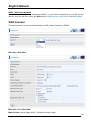
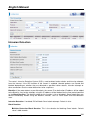
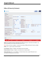
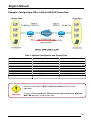
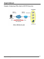
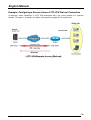
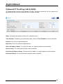
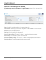
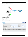
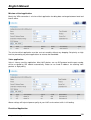
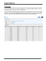
1
3G/ADSL2+ 802.11g VPN Router
User Manual
English
LINDY No. 52043
For Home and Office Use
Tested to Comply with
FCC Standards
www.LINDY.com
© LINDY ELECTRONICS LIMITED
&
LINDY-ELEKTRONIK GMBH
-
FIRST EDITION (Apr 2010)
English Manual
Table of Content
INTRODUCTION TO YOUR ROUTER ............................................................................................ 3
FEATURES .......................................................................................................................................... 3
IMPORTANT NOTE FOR USING THIS ROUTER .......................................................................... 6
PACKAGE CONTENTS ..................................................................................................................... 7
THE FRONT LEDS ............................................................................................................................. 8
THE REAR PORTS ............................................................................................................................. 9
CABLING .......................................................................................................................................... 10
CONNECTING YOUR ROUTER .................................................................................................... 12
FACTORY DEFAULT SETTINGS ................................................................................................... 21
Web Interface (Username and Password) ...................................................................................... 21
Device LAN IP settings .................................................................................................................. 21
ISP setting in WAN site .................................................................................................................. 21
DHCP server .................................................................................................................................. 21
LAN and WAN Port Addresses ....................................................................................................... 21
INFORMATION FROM YOUR ISP ................................................................................................. 22
CONFIGURING WITH YOUR WEB BROWSER .......................................................................... 23
STATUS ............................................................................................................................................. 25
ADSL Status ................................................................................................................................... 25
3G Status ........................................................................................................................................ 26
EWAN Status .................................................................................................................................. 27
iBurst Status ................................................................................................................................... 28
ARP Table ....................................................................................................................................... 29
DHCP Table ................................................................................................................................... 30
Routing Table ................................................................................................................................. 31
NAT Sessions .................................................................................................................................. 32
UPnP Portmap ............................................................................................................................... 32
PPTP Status ................................................................................................................................... 33
IPSec Status .................................................................................................................................... 33
L2TP Status .................................................................................................................................... 34
Email Status ................................................................................................................................... 34
Event Log ....................................................................................................................................... 35
Error Log ....................................................................................................................................... 35
Diagnostic ...................................................................................................................................... 36
QUICK START .................................................................................................................................. 37
CONFIGURATION ........................................................................................................................... 41
LAN - Local Area Network ............................................................................................................. 42
WAN - Wide Area Network ............................................................................................................. 64
System ............................................................................................................................................ 86
Firewall and Access Control .......................................................................................................... 94
VPN - Virtual Private Networks .................................................................................................... 112
QoS - Quality of Service .............................................................................................................. 144
Virtual Server (known as Port Forwarding) ................................................................................ 153
Wake on LAN ................................................................................................................................ 161
Time Schedule .............................................................................................................................. 162
Advanced ...................................................................................................................................... 164
LOGOUT ......................................................................................................................................... 172
PROBLEMS STARTING UP THE ROUTER ................................................................................. 173
PROBLEMS WITH THE WAN INTERFACE ................................................................................ 173
PROBLEMS WITH THE LAN INTERFACE................................................................................. 173
Table of content
2
English Manual
Chapter 1: Introduction
Introduction to your Router
Welcome to the 3G/ADSL2+ (802.11g) (VPN) Firewall Router. The router is an “all-in-one” ADSL
router, combining an ADSL modem, ADSL router and Ethernet network switch functionalities,
providing everything you need to get the machines on your network connected to the Internet over
your ADSL broadband connection. With features such as an ADSL Quick-Start wizard and DHCP
Server, you can be online in no time at all and with a minimum of fuss and configuration, catering for
first-time users to the guru requiring advanced features and control over their Internet connection and
network.
Features
Express Internet Access
The router complies with ADSL worldwide standards. It supports downstream rate up to 12/24
Mbps with ADSL2/2+, 8Mbps with ADSL. Users enjoy not only high-speed ADSL services but
also broadband multimedia applications such as interactive gaming, video streaming and realtime audio much easier and faster than ever. It is compliant with Multi-Mode standard (ANSI
T1.413, Issue 2; G.dmt (ITU G.992.1); G.lite (ITU G.992.2); G.hs (ITU G994.1); G.dmt.bis (ITU
G.992.3); G.dmt.bis.plus (ITU G.992.5)).
Virtual Private Network (VPN)
It allows user to make a tunnel with a remote site directly to secure the data transmission
among the connection. User can use embedded PPTP and L2TP client/server, IKE and IPSec
which are supported by this router to make a VPN connection or users can run the PPTP client
in PC and the router already provides IPSec and PPTP pass through function to establish a
VPN connection if the user likes to run the PPTP client in his local computer.
EWAN
Besides using 3G/ADSL to get connected to the Internet, the router offers its Ethernet port 1 as
a WAN port to be used to connect to Cable Modems and fiber optic lines. This alternative, yet
faster method to connect to the internet will provide users more flexibility to get online.
Dual WAN
Dual WAN is a new way of getting connected to the internet which is to use each two of the
3G/ADSL/EWAN to deal with the unexpected case and balance traffic load. That is a way of
improving greatly the robustness.
802.11g Wireless AP with WPA Support
With integrated 802.11g Wireless Access Point in the router, the device offers a quick and easy
access among wired network, wireless network and broadband connection (ADSL) with single
device simplicity, and as a result, mobility to the users. In addition to 54 Mbps 802.11g data
rate, it also interoperates backward with existing 802.11b equipment. The Wireless Protected
Access (WPA1 and WPA2) and Wireless Encryption Protocol (WEP) supported features
enhance the security level of data protection and access control via Wireless LAN.
Fast Ethernet Switch
A 4-port 10/100Mbps fast Ethernet switch is built in with automatic switching between MDI and
MDI-X for 10Base-T and 100Base-TX ports. An Ethernet straight or crossover cable can be
used directly for auto detection.
Chapter1: Introduction
3
English Manual
Multi-Protocol to Establish a Connection
It supports PPPoA (RFC 2364 - PPP over ATM Adaptation Layer 5), RFC 1483 encapsulation
over ATM (bridged or routed), PPP over Ethernet (RFC 2516), and IPoA (RFC1577) to establish
a connection with the ISP. The product also supports VC-based and LLC-based multiplexing.
Quick Installation Wizard
It supports a WEB GUI page to install this device quickly. With this wizard, end users can enter
the information easily which they get from their ISP, then surf the Internet immediately.
Universal Plug and Play (UPnP) and UPnP NAT Traversal
This protocol is used to enable simple and robust connectivity among stand-alone devices and
PCs from many different vendors. It makes network simple and affordable for users. UPnP
architecture leverages TCP/IP and the Web to enable seamless proximity networking in addition
to control and data transfer among networked devices. With this feature enabled, users can now
connect to Net meeting or MSN Messenger seamlessly.
Network Address Translation (NAT)
Allows multi-users to access outside resources such as the Internet simultaneously with one IP
address/one Internet access account. Many application layer gateway (ALG) are supported
such as web browser, ICQ, FTP, Telnet, E-mail, News, Net2phone, Ping, NetMeeting, IP phone
and others.
SOHO Firewall Security with DoS and SPI
Along with the built-in NAT natural firewall feature, the router also provides advanced hacker
pattern-filtering protection. It can automatically detect and block Denial of Service (DoS) attacks.
The router is built with Stateful Packet Inspection (SPI) to determine if a data packet is allowed
through the firewall to the private LAN.
Domain Name System (DNS) Relay
It provides an easy way to map the domain name (a friendly name for users such as
www.yahoo.com) and IP address. When a local machine sets its DNS server with this router’s
IP address, every DNS conversion request packet from the PC to this router will be forwarded to
the real DNS in the outside network.
Dynamic Domain Name System (DDNS)
The Dynamic DNS service allows you to alias a dynamic IP address to a static hostname. This
dynamic IP address is the WAN IP address. For example, to use the service, you must first
apply for an account from a DDNS service like http://www.dyndns.org/. More than 5 DDNS
servers are supported.
Quality of Service (QoS)
QoS gives you full control over which types of outgoing data traffic should be given priority by
the router, ensuring important data like gaming packets, customer information, or management
information move through the router ay lightning speed, even under heavy load. The QoS
features are configurable by source IP address, destination IP address, protocol, and port. You
can throttle the speed at which different types of outgoing data pass through the router, to
ensure P2P users don’t saturate upload bandwidth, or office browsing doesn’t bring client web
serving to a halt. In addition, or alternatively, you can simply change the priority of different
types of upload data and let the router sort out the actual speeds.
Virtual Server (“port forwarding”)
Users can specify some services to be visible from outside users. The router can detect
incoming service requests and forward either a single port or a range of ports to the specific
local computer to handle it. For example, a user can assign a PC in the LAN acting as a WEB
server inside and expose it to the outside network. Outside users can browse inside web
servers directly while it is protected by NAT. A DMZ host setting is also provided to a local
computer exposed to the outside network, Internet.
Chapter1: Introduction
4
English Manual
Rich Packet Filtering
Not only filters the packet based on IP address, but also based on Port numbers. It will filter
packets from and to the Internet, and also provides a higher level of security control.
Dynamic Host Configuration Protocol (DHCP) Client and Server
In the WAN site, the DHCP client can get an IP address from the Internet Service Provider (ISP)
automatically. In the LAN site, the DHCP server can allocate a range of client IP addresses and
distribute them including IP address, subnet mask as well as DNS IP address to local
computers. It provides an easy way to manage the local IP network.
Static and RIP1/2 Routing
It has routing capability and supports easy static routing table or RIP1/2 routing protocol.
Simple Network Management Protocol (SNMP)
It is an easy way to remotely manage the router via SNMP.
Web based GUI
It supports web based GUI for configuration and management. It is user-friendly and comes with
on-line help. It also supports remote management capability for remote users to configure and
manage this product.
Firmware Upgradeable
Device can be upgraded to the latest firmware through the WEB based GUI.
Rich Management Interfaces
It supports flexible management interfaces with local console port, LAN port, and WAN port.
Users can use terminal applications through the console port to configure and manage the
device, or Telnet, WEB GUI, and SNMP through LAN or WAN ports to configure and manage
the device.
Chapter1: Introduction
5
English Manual
Chapter 2: Installing the Router
Important note for using this router
Chapter 2: Installing the router
6
English Manual
Package Contents
3G/ADSL2+ 802.11g VPN Firewall Router
CD containing the online manual
RJ-11 ADSL/telephone Cable
Ethernet Cable
Console tool kit
Power adapter
A detachable antenna
Quick Start Guide (in the CD)
Chapter 2: Installing the router
7
English Manual
The Front LEDs
LED
Meaning
Lit when power turns ON. Lit in red means the system is failed. To restart
the device or connect service provider for support.
1
Power
2
Lit when one of LAN ports connected to an Ethernet device.
LAN Port
The speed of transmission hits 100Mbps appears Green;
1X
4X
The speed of transmission hits 10Mbps appears Orange.
(RJ-45 connector)
Blinking when data is Transmitted / Received.
3
USB
Lit when the device connected to a USB device.
Flash when the device is sending/receiving data.
4
Wireless
Lit green when the wireless connection is established.
Flashes when the device is sending/receiving data.
Flash once per second while wi-fi protected setup is in progress.
5
Mail
Lit green when there are emails in the Inbox.
6
DSL
Lit Green when the device is successfully connected to an ADSL
DSLAM.(“line sync”).
Internet
Lit green when IP connected.
Flashes green when IP connected and IP traffic is passing through the
device.
Lit red when device attempted to become IP connected and failed.
Lit off when device in bridged mode or when connection WAN is absent.
7
Chapter 2: Installing the router
8
English Manual
The Rear Ports
The Ethernet Port # 4 can be used as a console port. You need a special
console tool which already includes in the package to connect with LAN
port 4 and PC’s RS-232 port (9-pin serial port).
Port
Antenna
1
Meaning
Connect the detachable antenna to this port.
2
DSL
Connect the supplied RJ-11 (“telephone”) cable on this port
when connecting to the ADSL/telephone network.
3
USB
Connect the USB cable on this port.
LAN
Connect a UTP Ethernet cable (Cat-5 or Cat-5e) to one of the
LAN ports when connecting to a PC or an office/home network
4X of 10Mbps or 100Mbps.
Caution: Port 4 can be either a LAN or Console port at a time
but not both.
4
1X
(RJ-45 connector)
5
WPS
Push WPS button to trigger Wi-Fi Protected Setup function.
6
RESET
To be sure the device is being turned on. Press RESET button
for:
1-3 seconds: quick reset the device.
6 seconds above, and power off, power on the device:
restore to factory default settings. (Cannot login to the router or
forgot your Username/Password. Press the button for more
than 6 seconds).
Caution: After pressing the RESET button for more than 6
seconds, to be sure you power cycle the device again.
7
Power
Connect the supplied power adapter to this jack.
8
Power Switch
Power ON/OFF switch
Chapter 2: Installing the router
9
English Manual
Cabeling
One of the most common causes of problems is the bad cabling or ADSL line(s). Make sure that all
connected devices are turned on. On the front of the product is a bank of LEDs. Verify that the LAN
Link and ADSL line LEDs are lit. If they are not, verify that you are using the proper cables.
Ensure that all other devices connected to the same telephone line as your router (e.g. telephones,
fax machines, analogue modems) have a line filter connected between them and the wall socket
(unless you are using a Central Splitter or Central Filter installed by a qualified and licensed
electrician), and ensure that all line filters are correctly installed and the right way around. Missing line
filters or line filters installed the wrong way around can cause problems with your ADSL connection,
including causing frequent disconnections.
Chapter 2: Installing the router
10
English Manual
Chapter 3: Basic Installation
The router can be configured with your web browser. A web browser is included as a standard
application in the following operating systems: Windows 7, Linux, Mac OS, Windows
98/NT/2000/XP/Me, etc. The product provides an easy and user-friendly interface for configuration.
Please check your PC’s network components. The TCP/IP protocol stack and Ethernet network
adapter must be installed. If not, please refer to your Windows-related or other operating system
manuals.
There are ways to connect with the router, either through an external repeater hub to the router or
directly connecting with PCs. However, to be sure PCs have an Ethernet interface installed properly
prior to connecting to the router device. You ought to configure your PCs to obtain an IP address
through a DHCP server or a fixed IP address that must be in the same subnet as the router. The
default IP address of the router is 192.168.1.254 and the subnet mask is 255.255.255.0 (i.e. any
attached PC must be in the same subnet, and have an IP address in the range of 192.168.1.1 to
192.168.1.253). The best and easiest way is to configure the PC to get an IP address automatically
from the router using DHCP. If you encounter any problem accessing the router’s web interface it may
also be advisable to uninstall any kind of software firewall on your PCs, as they can cause problems
accessing the 192.168.1.254 IP address of the router. Users should make their own decisions on how
to best protect their network.
Please follow the steps below for your PC’s network environment installation.
Any TCP/IP capable workstation can be used to communicate with or through
the router. To configure other types of workstations, please consult the
manufacturer’s documentation.
Chapter 3: Basic Installation
11
English Manual
Connecting Your Router
1. Connect this router to a LAN (Local Area Network) and the ADSL/telephone (ADSL) network.
2. Power on the device.
3. Make sure the Power is lit steadily and that the LAN LED is lit.
4. Connect RJ-11 cable to LINE Port when connecting to the telephone wall jack.
5. Connect USB 2.0 cable.
Chapter 3: Basic Installation
12
English Manual
Configuring PCs in Windows 7
1. Go to Start. Click on Control Panel.
Then click on Network and Internet.
2. When the Network and Sharing
Center window pops up, select and click
on Change adapter settings on the left
window panel.
3. Select the Local Area Connection,
and right click the icon to select
Properties.
Chapter 3: Basic Installation
13
English Manual
4. Select Internet Protocol Version 4
(TCP/IPv4) then click Properties.
5. In the TCP/IPv4 properties window,
select the Obtain an IP address
automatically and Obtain DNS Server
address automatically radio buttons.
Then click OK to exit the setting.
6. Click OK again in the Local Area
Connection Properties window to apply
the new configuration.
Chapter 3: Basic Installation
14
English Manual
Configuring PCs in Windows Vista
1. Go to Start. Click on Network.
2. Then click on Network and Sharing
Center at the top bar
3. When the Network and Sharing
Center window pops up, select and click
on Manage network connections on the
left window column.
4. Select the Local Area Connection,
and right click the icon to select
Properties.
Chapter 3: Basic Installation
15
English Manual
5. Select Internet Protocol Version 4
(TCP/IPv4) then click Properties.
6. In the TCP/IPv4 properties window,
select the Obtain an IP address
automatically and Obtain DNS Server
address automatically radio buttons.
Then click OK to exit the setting.
7. Click OK again in the Local Area
Connection Properties window to
apply the new configuration
Chapter 3: Basic Installation
16
English Manual
Configuring PCs in Windows XP
1.
2.
Go to Start / Control Panel (in Classic View). In the Control
Panel, double-click Network Connections.
Double-click Local Area Connection. (See Figure 3.1)
Figure 3.1: LAN Area Connection
3.
In the LAN Area Connection Status window, click
Properties. (See Figure 3.2)
Figure 3.2: LAN Connection Status
4.
Select Internet Protocol (TCP/IP) and click Properties.
(See Figure 3.3)
Figure 3.3: TCP / IP
5.
6.
Select the Obtain an IP address automatically and Obtain
DNS server address automatically radio buttons. (See
Figure 3.4)
Click OK to finish the configuration.
Figure 3.4: IP Address & DNS
Configuration
Chapter 3: Basic Installation
17
English Manual
Configuring PCs in Windows 2000
1. Go to Start / Settings / Control Panel. In the Control Panel,
double-click Network and Dial-up Connections.
2. Double-click Local Area (“LAN”) Connection. (See Figure
3.5)
Figure 3.5: LAN Area Connection
3. In the LAN Area Connection Status window, click
Properties. (See Figure 3.6)
Figure 3.6: LAN Connection Status
4. Select Internet Protocol (TCP/IP) and click Properties.
(See Figure 3.7)
Figure 3.7: TCP / IP
5. Select the Obtain an IP address automatically and Obtain
6.
DNS server address automatically radio buttons. (See
Figure 3.8)
Click OK to finish the configuration.
Chapter 3: Basic Installation
Figure 3.8: IP Address & DNS
18
Configuration
English Manual
Configuring PC in Windows 95/98/ME
1.
2.
3.
Go to Start / Settings / Control Panel. In the Control Panel,
double-click Network and choose the Configuration tab.
Select TCP / IP -> NE2000 Compatible, or the name of any
Network Interface Card (NIC) in your PC. (See Figure 3.9)
Click Properties.
Figure 3.9: TCP / IP
4.
Select the IP Address tab. In this page, click the Obtain an
IP address automatically radio button. (See Figure 3.10)
Figure 3.10: IP Address
5.
6.
Then select the DNS Configuration tab. (See Figure 3.11)
Select the Disable DNS radio button and click OK to finish
the configuration.
Figure 3.11: DNS Configuration
Chapter 3: Basic Installation
19
English Manual
Configuring PC in Windows NT4.0
1. Go to Start / Settings / Control Panel. In the Control Panel,
2.
double-click Network and choose the Protocols tab.
Select TCP/IP Protocol and click Properties. (See Figure
3.12)
Figure 3.12: TCP / IP
3. Select the Obtain an IP address from a DHCP server radio
button and click OK. (See Figure 3.13)
Figure 3.13: IP Address
Chapter 3: Basic Installation
20
English Manual
Factory Default Settings
Before configuring your, you need to know the following default settings.
Web Interface (Username and Password)
Username: admin
Password: admin
The default username and password are “admin” and “admin” respectively.
If you ever forget the username/password to login to the router, you may
press the RESET button up to 6 seconds to restore the factory default
settings.
Attention
Attention
Caution: After pressing the RESET button for more than 6 seconds, to be sure you
power cycle the device again.
Device LAN IP settings
IP Address: 192.168.1.254
Subnet Mask: 255.255.255.0
ISP setting in WAN site
PPPoE
DHCP server
DHCP server is enabled.
Start IP Address: 192.168.1.100
IP pool counts: 100
LAN and WAN Port Addresses
The parameters of LAN and WAN ports are pre-set in the factory. The default values are shown as
below.
LAN Port
WAN Port
IP address
192.168.1.254
Subnet Mask
255.255.255.0
DHCP server function
Enabled
The PPPoE function is enabled
to automatically get the WAN
port configuration from the ISP.
IP
addresses
for 100 IP addresses continuing from
distribution to PCs
192.168.1.100 through 192.168.1.199
Chapter 3: Basic Installation
21
English Manual
Information from your ISP
Before configuring this device, you have to check with your ISP (Internet Service Provider) to find out
what kind of service is provided such as DHCP (Obtain an IP Address Automatically, Static IP (Fixed
IP Address) and PPPoE.
Gather the information as illustrated in the following table and keep it for reference.
PPPoE(RFC2516)
VPI/VCI, VC / LLC-based multiplexing, Username, Password, Service Name,
and Domain Name System (DNS) IP address (it can be automatically
assigned by your ISP when you connect or be set manually).
PPPoA(RFC2364)
VPI/VCI, VC / LLC-based multiplexing, Username, Password and Domain
Name System (DNS) IP address (it can be automatically assigned by your
ISP when you connect or be set manually).
MPoA(RFC1483/RF
C2684)
VPI/VCI, VC / LLC-based multiplexing, IP address, Subnet mask, Gateway
address, and Domain Name System (DNS) IP address (it is a fixed IP
address).
IPoA(RFC1577)
VPI/VCI, VC / LLC-based multiplexing, IP address, Subnet mask, Gateway
address, and Domain Name System (DNS) IP address (it is a fixed IP
address).
Pure Bridge
VPI/VCI, VC / LLC-based multiplexing to use Bridged Mode.
Chapter 3: Basic Installation
22
English Manual
Configuring with your Web Browser
Open your web browser, enter the IP address of your router, which by default is 192.168.1.254, and
click “Go”, a user name and password window prompt will appear. The default username and
password are “admin” and “admin” respectively. (See Figure 3.14)
Figure 3.14: User name & Password Prompt Window
Congratulations! You are now successfully logon to the Router!
Chapter 3: Basic Installation
23
English Manual
Chapter 4: Configuration
At the configuration homepage, the left navigation pane where bookmarks are provided links you
directly to the desired setup page, including:
Status
- ADSL Status
- 3G Status
- EWAN Status
- iBurst Status
- ARP Table
- DHCP Table
- Routing Table
- NAT Sessions
- UPnP Portmap
- PPTP Status
- IPSec Status
- L2TP Status
- Email Status
- Event Log
- Error Log
- Diagnostic
Quick Start
Configuration
- LAN
- WAN
- System
- Firewall
- VPN
- QoS
- Virtual Server
- Wake on LAN
- Time Schedule
- Advanced
Language (provides user interface in English and French languages)
Chapter 4: Configuration
24
English Manual
Status
ADSL Status
This section displays the ADSL overall status, which shows a number of helpful information such as
DSP firmware version.
Chapter 4: Configuration
25
English Manual
3G Status
This section displays the 3G Card’s overall status, which shows you a number of helpful information
such as the current signal strength and statistics on current and total bytes transferred and received.
Status: The current status of the 3G card.
Signal Strength: The signal strength bar indicates current 3G signal strength.
Network Name: The network name that the device is connected to.
Card Name: The name of the 3G card.
Card Firmware: The current firmware for the 3G card.
Current TX Bytes / Packets: The statistics of transmission, count for this call.
Current RX Bytes / Packets: The statistics of receive, count for this call.
Total TX Bytes / Packets: The statistics of transmission, count from system ready
Total RX Bytes / Packets: The statistics of receive, count from system ready
Chapter 4: Configuration
26
English Manual
EWAN Status
Besides using 3G/ADSL to get connected to the Internet, the router offers its Ethernet port 1 as a
WAN port to be used to connect to Cable Modems and fiber optic lines. This alternative, yet faster
method to connect to the internet will provide users more flexibility to get online.
Total TX Bytes / Packets: The statistics of total data transmission in bytes / packets since
system ready.
Total RX Bytes / Packets: The statistics of total data received in bytes / packets since system
ready.
Chapter 4: Configuration
27
English Manual
iBurst Status
Displays additional information of the 3G status when iBurst function is enabled in the 3G
configuration such as its signal strength, card name, connection status and port class Ethernet.
Card Name: The name of the card.
Signal Strength: The signal strength bar indicates the current signal strength.
Current TX Bytes / Packets: The statistics of data transmission in bytes / packets during a call.
Current RX Bytes / Packets: The statistics of data received in bytes / packets during a call.
Total TX Bytes / Packets: The statistics of total data transmission in bytes / packets since system
ready.
Total RX Bytes / Packets: The statistics of total data received in bytes / packets since system ready.
Chapter 4: Configuration
28
English Manual
ARP Table
This section displays the router’s ARP (Address Resolution Protocol) Table, which shows the
mapping of Internet (IP) addresses to Ethernet (MAC) addresses. This is useful as a quick way of
determining the MAC address of the network interface of your PCs to use with the router’s Firewall –
MAC Address Filter function. See the Firewall section of this manual for more information on this
feature.
IP Address: A list of IP addresses of devices on your LAN (Local Area Network).
MAC Address: The MAC (Media Access Control) addresses for each device on your LAN.
Interface: The interface name (on the router) that this IP Address connects to.
Static: Static status of the ARP table entry:
“no” for dynamically-generated ARP table entries.
“yes” for static ARP table entries added by the user.
Chapter 4: Configuration
29
English Manual
DHCP Table
Leased: The DHCP assigned IP addresses information.
Expired: The expired IP addresses information.
Permanent: The fixed host mapping information
Leased Table
IP Address: The IP address that assigned to client.
MAC Address: The MAC address of client.
Client Host Name: The Host Name (Computer Name) of client.
Expiry: The current lease time of client.
Chapter 4: Configuration
30
English Manual
Routing Table
Routing Table
Valid: It indicates a successful routing status.
Destination: The IP address of the destination network.
Netmask: The destination Netmask address.
Gateway/Interface: The IP address of the gateway or existing interface that this route will use.
Cost: The number of hops counted as the cost of the route.
RIP Routing Table
Destination: The IP address of the destination network.
Netmask: The destination Netmask address.
Gateway: The IP address of the gateway that this route will use.
Cost: The number of hops counted as the cost of the route.
Chapter 4: Configuration
31
English Manual
NAT Sessions
This section lists all current NAT sessions between interface of types external (WAN) and internal
(LAN).
UPnP Portmap
The section lists all port-mapping established using UPnP (Universal Plug and Play. See Advanced
section of this manual for more details on UPnP and the router’s UPnP configuration options.
Chapter 4: Configuration
32
English Manual
PPTP Status
This shows details of your configured PPTP VPN Connections.
Name: The name you assigned to the particular PPTP connection in your VPN configuration.
Type: The type of connection (dial-in/dial-out).
Enable: Whether the connection is currently enabled.
Active: Whether the connection is currently active.
Tunnel Connected: Whether the VPN Tunnel is currently connected.
Call Connected: If the Call for this VPN entry is currently connected.
Encryption: The encryption type used for this VPN connection.
IPSec Status
This shows details of your configured IPSec VPN Connections.
Name: The name you assigned to the particular VPN entry.
Active: Whether the VPN Connection is currently Active.
Connection State: Whether the VPN is Connected or Disconnected.
Statistics: Statistics for this VPN Connection.
Local Subnet: The local IP Address or Subnet used.
Chapter 4: Configuration
33
English Manual
Remote Subnet: The Subnet of the remote site.
Remote Gateway: The Remote Gateway IP address.
SA: The Security Association for this VPN entry.
L2TP Status
This shows details of your configured L2TP VPN Connections.
Name: The name you assigned to the particular L2TP connection in your VPN configuration.
Type: The type of connection (dial-in/dial-out).
Enable: Whether the connection is currently enabled.
Active: Whether the connection is currently active.
Tunnel Connected: Whether the VPN Tunnel is currently connected.
Call Connected: If the Call for this VPN entry is currently connected.
Encryption: The encryption type used for this VPN connection.
Email Status
Details and status for the Email Account you have configured the router to check. Please see the
Advanced section of this manual for details on this function.
Chapter 4: Configuration
34
English Manual
Event Log
This page displays the router’s Event Log entries. Major events are logged to this window, such as
when the router’s ADSL connection is disconnected, as well as Firewall events when you have
enabled Intrusion or Blocking Logging in the Configuration – Firewall section of the interface.
Please see the Firewall section of this manual for more details on how to enable Firewall logging.
Error Log
Any errors encountered by the router (e.g. invalid names given to entries) are logged to this window.
Chapter 4: Configuration
35
English Manual
Diagnostic
It tests the connection to computer(s) which is connected to LAN ports and also the WAN Internet
connection. If PING www.google.com is shown FAIL and the rest is PASS, you ought to check your
PC’s DNS settings is set correctly.
Chapter 4: Configuration
36
English Manual
Quick Start
1. Click Quick Start. Select the connect mode you want. There are three options you can choose,
ADSL, EWAN and 3G. Select ADSL from Connect Mode drop-down menu, and click Continue.
2. If your ADSL line is not ready, you need to check your ADSL line has been set or not.
3. If your ADSL line is ready, the screen appears ADSL Line is Ready. Choose Auto radio button and
click Apply. It will automatically scan the recommended mode for you. Manually mode makes you to
set the ADSL line by manual. (If you choose Manually, you will directly go to step 5.)
4. The list below has different mode applied for your choice. Choose 0/33/PPPoE (Recommended)
and click Apply.
Chapter 4: Configuration
37
English Manual
5. Please enter “Username” and “Password” as supplied by your ISP (Internet Service Provider) and
click Apply to continue.
Profile Port: Select the connection mode. There are ADSL EWAN and 3G.
Protocol: Select the protocol mode. The default mode is PPPoE.
VPI/VCI: Enter the VPI and VCI information provided by your ISP.
Username: Enter the username provided by your ISP.
Password: Enter the password provided by your ISP.
Service Name: This item is for identification purposes. If it is required, your ISP provides you the
information.
Authentication Protocol: Default is Auto. Your ISP advises on using Chap or Pap.
Chapter 4: Configuration
38
English Manual
IP Address: Your WAN IP address. Leave this at 0.0.0.0 to obtain automatically an IP address from
your ISP.
6. Configure the Wireless LAN setting.
WLAN Service: Default setting is set to Enable. If you want to use wireless, both 802.11g
and 802.11b device in your network, you can select Enable.
ESSID: The ESSID is the unique name of a wireless access point (AP) to be distinguished
from another. For security propose, change to a unique ID name to the AP which is already
built-in to the router’s wireless interface. It is case sensitive and must not excess 32
characters. Make sure your wireless clients have exactly the ESSID as the device, in order to
get connected to your network.
ESSID Broadcast: It is function in which transmits its ESSID to the air so that when wireless
client searches for a network, router can then be discovered and recognized. Default setting
is Enable.
Enable: When Enable is selected, you can allow anybody with a wireless client to be
able to locate the Access Point (AP) of your router.
Disable: Select Disable if you do not want broadcast your ESSID. When select
Disable, no one will be able to locate the Access Point (AP) of your router.
Channel ID: Select the ID channel that you would like to use.
Security Mode: You can disable or enable with WPA or WEP for protecting wireless
network. The default mode of wireless security is Disable.
7. Wait for the configuration.
Chapter 4: Configuration
39
English Manual
8. When ADSL is synchronic, it will appear “check”.
Chapter 4: Configuration
40
English Manual
Configuration
When you click this item, you get following sub-items to configure the ADSL router.
- LAN, WAN, System, Firewall, VPN, QoS, Virtual Server, Wake on LAN, Time Schedule and
Advanced
These functions are described below in the following sections.
Chapter 4: Configuration
41
English Manual
LAN - Local Area Network
Here are the items within the LAN section: Bridge Interface, Ethernet, IP Alias, Ethernet Client
Filter, Wireless, Wireless Security, Wireless Client Filter, WPS, Port Setting and DHCP Server.
Bridge Interface
You can setup member ports for each VLAN group under Bridge Interface section. From the example,
two VLAN groups need to be created.
Ethernet: P1 (Port 1)
Ethernet1: P2, P3 and P4 (Port 2, 3, 4). Uncheck P2, P3, P4 from Ethernet VLAN port first.
Note: You should setup each VLAN group with caution. Each Bridge Interface is arranged in this order.
Bridge Interface
ethernet
ethernet1
ethernet2
ethernet3
VLAN Port (Always starts with)
P1 / P2 / P3 / P4
P2 / P3 / P4
P3 / P4
P4
Management Interface: To specify which VLAN group has possibility to do device management, like
doing web management.
Note: NAT/NAPT can be applied to management interface only.
Chapter 4: Configuration
42
English Manual
Ethernet
Primary IP Address
IP Address: The default IP on this router.
Subnet Mask: The default subnet mask on this router.
RIP: RIP v1, RIP v2, and RIP v2 Multicast. Check to enable RIP function.
IP Alias
This function creates multiple virtual IP interfaces on this router. It helps to connect two or more local
networks to the ISP or remote node. In this case, an internal router is not required.
IP Address: Specify an IP address on this virtual interface.
SubNetmask: Specify a subnet mask on this virtual interface.
Security Interface: Specify the firewall setting on this virtual interface.
Internal: The network is behind NAT. All traffic will do network address translation when sending out
to Internet if NAT is enabled.
External: There is no NAT on this IP interface and connected to the Internet directly. Mostly it will be
used when providing multiple public IP addresses by ISP. In this case, you can use public IP address
in local network which gateway IP address point to the IP address on this interface.
DMZ: Specify this network to DMZ area. There is no NAT on this interface.
Chapter 4: Configuration
43
English Manual
Ethernet Client Filter
The Ethernet Client Filter supports up to 16 Ethernet network machines that helps you to manage
your network control to accept traffic from specific authorized machines or can restrict unwanted
machine(s) to access your LAN.
There are no pre-define Ethernet MAC address filter rules; you can add the filter rules to meet your
requirements.
Ethernet Client Filter: Default setting is set Disable.
Allowed: check to authorize specific device accessing your LAN by insert the MAC Address
in the space provided or click
. Make sure your PC’s MAC is listed.
Blocked: check to prevent unwanted device accessing your LAN by insert the MAC Address
in the space provided or click
. Make sure your PC’s MAC is not listed.
The maximum client is 16. The MAC addresses are 6 bytes long; they are presented only in
hexadecimal characters. The number 0 - 9 and letters a - f are acceptable.
Note: Follow the MAC Address Format xx:xx:xx:xx:xx:xx. Semicolon ( : ) must be included.
Candidates: automatically detects devices connected to the router through the Ethernet.
, Active PC in LAN
Chapter 4: Configuration
44
English Manual
Active PC in LAN displays a list of individual Ethernet device’s IP Address & MAC Address which
connecting to the router.
You can easily by checking the box next to the IP address to be blocked or allowed. Then, Add to
insert to the Ethernet Client Filter table. The maximum Ethernet client is 16.
Wireless
Parameters
WLAN Service: Default setting is set to Enable. If you do not have any wireless, both 802.11g and
802.11b, device in your network, select Disable.
Mode: The default setting is 802.11b+g (Mixed mode). If you do not know or have both 11g and 11b
devices in your network, then keep the default in mixed mode. From the drop-down manual, you can
select 802.11g if you have only 11g card. If you have only 11b card, then select 802.11b.
ESSID: The ESSID is the unique name of a wireless access point (AP) to be distinguished from
another. For security purpose, change the default wlan-ap to a unique ID name to the AP which is
already built-in to the router’s wireless interface. It is case sensitive and must not excess 32
Chapter 4: Configuration
45
English Manual
characters. Make sure your wireless clients have exactly the ESSID as the device, in order to get
connected to your network.
Note: It is case sensitive and must not excess 32 characters.
ESSID Broadcast: It is function in which transmits its ESSID to the air so that when wireless client
searches for a network, router can then be discovered and recognized. Default setting is Enabled.
Disable: If you do not want broadcast your ESSID. Any client uses “any” wireless setting
cannot discover the Access Point (AP) of your router.
Enable: Any client that using the “any” setting can discover the Access Point (AP) in
Regulation Domain: There are seven Regulation Domains for you to choose from, including North
America (N.America), Europe, France, etc. The Channel ID will be different based on this setting.
Channel ID: Select the wireless connection ID channel that you would like to use.
Note: Wireless performance may degrade if select ID channel is already being occupied by other AP(s).
TX PowerLevel: It is a function that enhances the wireless transmitting signal strength. User may
adjust this power level from minimum 1 up to maximum 127.
Note: The Power Level maybe different in each access network user premises environment and choose the
most suitable level for your network.
Connected: Representing in true or false. That it is the connection status between the system and
the build-in wireless card.
AP MAC Address: It is a unique hardware address of the Access Point.
AP Firmware Version: The Access Point firmware version.
WMM: This feature works concurrently with QoS that enables the system to prioritize the flow of
data packets according to 4 categories: Voice, Video, Best Efforts and Background.
Enable: Click to activate WMM feature.
Disable: Click to deactivate WMM feature.
Wireless Distribution System (WDS)
It is a wireless access point mode that enables wireless link and communication with other access
point. It is easy to be installed simply to define peer’s MAC address of the connected AP. WDS takes
advantages of cost saving and flexibility which no extra wireless client device is required to bridge
between two access points and extending an existing wired or wireless infrastructure network to
create a larger network. It can connect up to 4 wireless APs for extending cover range at the same
time.
In addition, WDS enhances its link connection security in WEP mode, WEP key encryption must be
the same for both access points.
WDS Service: The default setting is Disabled. Check Enable radio button to activate this function.
1. Peer WDS MAC Address: It is the associated AP’s MAC Address. It is important that your peer’s
AP must include your MAC address in order to acknowledge and communicate with each other.
2. Peer WDS MAC Address: It is the second associated AP’s MAC Address.
3. Peer WDS MAC Address: It is the third associated AP’s MAC Address.
Chapter 4: Configuration
46
English Manual
4. Peer WDS MAC Address: It is the fourth associated AP’s MAC Address.
Note: For MAC Address, Semicolon ( : ) must be included.
Chapter 4: Configuration
47
English Manual
Wireless Security
You can disable or enable with WPA or WEP for protecting wireless network.
The default mode of wireless security is disabled.
WPA-PSK / WPA2-PSK / WEP
Security Mode: You can disable or enable with WPA or WEP for protecting wireless
network. The default mode of wireless security is Disable.
WPA Algorithms: There are two types of the WPA-PSK, WPA-PSK and WPA2-PSK. The WPA-PSK
adapts the TKIP (Temporal Key Integrity Protocol) encrypted algorithms, which incorporates Message
Integrity Code (MIC) to provide protection against hackers. The WPA2-PSK adapts CCMP (Cipher
Block Chaining Message Authentication Code Protocol) of the AES (Advanced Encryption Security)
algorithms.
WPA Shared Key: The key for network authentication. The input format is in character style and key
size should be in the range between 8 and 63 characters.
Group Key Renewal: The period of renewal time for changing the security key automatically
between wireless client and Access Point (AP). Default value is 600 seconds.
Chapter 4: Configuration
48
English Manual
WEP
WEP Authentication: To prevent unauthorized wireless stations from accessing data
transmitted over the network, the router offers secure data encryption, known as WEP. If you
require high security for transmissions, there are two options to select from: Open System,
Share key.
WEP Encryption: To prevent unauthorized wireless stations from accessing data transmitted over
the network, the router offers highly secure data encryption, known as WEP. If you require high
security for transmissions, there are two alternatives to select from: WEP 64 and WEP 128. WEP 128
will offer increased security over WEP 64.
Passphrase: This is used to generate WEP keys automatically based upon the input string and a
pre-defined algorithm in WEP64 or WEP128.
Default Used WEP Key: Select the encryption key ID; please refer to Key (1~4) below.
Key (1-4): Enter the key to encrypt wireless data. To allow encrypted data transmission, the WEP
Encryption Key values on all wireless stations must be the same as the router. There are four keys for
your selection. The input format is in HEX style, 10 and 26 HEX codes are required for WEP64 and
WEP128 respectively.
Chapter 4: Configuration
49
English Manual
Wireless Client / MAC Address Filter
The MAC Address supports up to 16 wireless network machines and helps you manage your network
control to accept traffic from specific authorized machines or to restrict unwanted machine(s) to
access your LAN.
There are no pre-define MAC Address filter rules; you can add the filter rules to meet your
requirements.
Wireless Client Filter: Default setting is set to Disable.
Allowed: To authorize specific device accessing your LAN by insert the MAC Address in the
space provided or click
. Make sure your PC’s MAC is listed.
Blocked: To prevent unwanted device accessing the LAN by insert the MAC Address in the
. Make sure your PC’s MAC is not listed.
space provided or click
The maximum client is 16. The MAC addresses are 6 bytes long; they are presented only in
hexadecimal characters. The number 0 - 9 and letters a - f are acceptable.
Note: Follow the MAC Address Format xx:xx:xx:xx:xx:xx. Semicolon ( : ) must be included.
Candidates: it automatically detects devices connected to the router through the Wireless.
→Associated Wireless Clients
Associate Wireless Client displays a list of individual wireless device’s MAC Address that currently
connects to the router. You can easily by checking the box next to the MAC address to be blocked or
allowed. Then, Add to insert to the Wireless Client (MAC Address) Filter table. The maximum
Wireless client is 16.
Chapter 4: Configuration
50
English Manual
WPS
WPS feature is follow Wi-Fi Alliance WPS standard and it easily set up security-enabled Wi-Fi
networks in the home and small office environment. It is reduced by half the user steps to configure a
network and supports two methods that are familiar to most consumers to configure a network and
enable security.
Set up of security-enabled Wi-Fi network
Step 1: Note down the AP’s PIN from Web (Ex: 78749887).
Step 2: Open wireless client’s WPS utility (Ex: Atheros Jumpstart WPS utility), select “Configure a
wireless network” and apply “next” button.
Step 3: Enter AP’s PIN into the utility and click on the “next” button.
Chapter 4: Configuration
51
English Manual
Step 4: These are two ways to trigger AP as Enrolee role, you can choose one to do it.
Push AP’s WPS button 1 second and release it.
In the AP’s WPS configuration page, change Role to “Enrollee” and apply “Start”
button.
Step 5: Jumpstart WPS utility search WPS AP.
Chapter 4: Configuration
52
English Manual
Step 6: SSID and security will be generated automatically (You can change it) and apply “next”
button.
Step 7: WPS set up complete. And you have set up security-enabled Wi-Fi networks.
Chapter 4: Configuration
53
English Manual
Chapter 4: Configuration
54
English Manual
Set up of security-enabled Wi-Fi network using WCN in Vista
Step 1: Note down the AP’s PIN from Web (Ex: 78749887).
Step 2: In Vista’s Control Panel, select Network and Internet and choose View network computers
and devices. Double click the “ADSL Firewall Router” icon and enter the AP’s PIN code then click
“Next”.
Step 3: Enter the AP SSID and apply “Next” button.
Chapter 4: Configuration
55
English Manual
Step 4: Enter the Passphrase and apply “Next” button.
Step 5: WCN set up complete. And you have set up security-enabled Wi-Fi networks.
Chapter 4: Configuration
56
English Manual
Chapter 4: Configuration
57
English Manual
Adding a new WPS device (wireless client) to a network - Use PBC Method
Step 1: Push AP’s WPS button more than one second and you will see AP’s WLAN led will flashing
per second.
Step 2: Open wireless client’s WPS utility, select “Join a wireless network” and apply “next” button.
Note: After you push AP’s WPS button, below steps should be completed between 2 minutes.
Step 3: Select “Push the button on my access point” and apply “next” button.
Step 4: New WPS device have join into the wireless network.
Chapter 4: Configuration
58
English Manual
Chapter 4: Configuration
59
English Manual
Adding a new WPS device (wireless client) to a network - Use PIN Method
Step 1: Open wireless client’s WPS utility, select “Join a wireless network” and apply “next” button.
Step 2: Note down the wireless client’s PIN (Ex: 41538142) and apply “Start” button for active
wireless client WPS PIN method.
Step 3: Enter wireless client’s PIN into “Enrollee’s PIN” of Web and apply “Start” button.
Chapter 4: Configuration
60
English Manual
Step 4: New WPS device have join into the wireless network.
Chapter 4: Configuration
61
English Manual
Port Setting
This section allows you to configure the settings for the router’s Ethernet ports to solve some of the
compatibility problems that may be encountered while connecting to the Internet, as well allowing
users to tweak the performance of their network.
Port # Connection Type: There are Six options to choose from: Auto, disable, 10M half-duplex, 10M
full-duplex, 100M half-duplex, 100M full-duplex and Disable. Sometimes, there are Ethernet
compatibility problems with legacy Ethernet devices, and you can configure different types to solve
compatibility issues. The default is Auto, which users should keep unless there are specific problems
with PCs not being able to access your LAN.
IPv4 TOS priority Control (Advanced users): TOS, Type of Services, is the 2nd octet of an IP
packet. Bits 6-7 of this octet are reserved and bit 0-5 are used to specify the priority of the packet.
This feature uses bits 0-5 to classify the packet’s priority. If the packet is high priority, it will flow first
and will not be constrained by the Rate Limit. Therefore, when this feature is enabled, the router’s
Ethernet switch will check the 2nd octet of each IP packet. If the value in the TOS field matches the
checked values in the table (0 to 63), this packet will be treated as high priority.
Chapter 4: Configuration
62
English Manual
DHCP Server
You can disable or enable the DHCP (Dynamic Host Configuration Protocol) server or enable the
router’s DHCP relay functions. The DHCP protocol allows your router to dynamically assign IP
addresses to PCs on your network if they are configured to obtain IP addresses automatically.
To disable the router’s DHCP Server, check Disabled and click Next, then click Apply. When the
DHCP Server is disabled you will need to manually assign a fixed IP address to each PCs on your
network, and set the default gateway for each PCs to the IP address of the router (by default this is
192.168.1.254).
To configure the router’s DHCP Server, check DHCP Server and click Next. You can then configure
parameters of the DHCP Server including the IP pool (starting IP address and ending IP address to
be allocated to PCs on your network), lease time for each assigned IP address (the period of time the
IP address assigned will be valid), DNS IP address and the gateway IP address. These details are
sent to the DHCP client (i.e. your PC) when it requests an IP address from the DHCP server. Click
Apply to enable this function. If you check “Use Router as a DNS Server”, the ADSL Router will
perform the domain name lookup, find the IP address from the outside network automatically and
forward it back to the requesting PC in the LAN (your Local Area Network).
If you check DHCP Relay Agent and click Next, then you will have to enter the IP address of the
DHCP server which will assign an IP address back to the DHCP client in the LAN. Use this function
only if advised to do so by your network administrator or ISP.
Click Apply to enable this function.
Chapter 4: Configuration
63
English Manual
WAN - Wide Area Network
WAN refers to your Wide Area Network connection, i.e. your router’s connection to your ISP and the
Internet. Here are the items within the WAN section: WAN Interface, WAN Profile and ADSL Mode.
WAN Interface
The factory default has the Connection Mode as ADSL and the Protocol as PPPoE.
Main Port—Dual WAN
Main Port: Select Dual WAN.
Mode Failover: Set to trigger ADSL / 3G failover function ready.
Chapter 4: Configuration
64
English Manual
WAN1: Select “ADSL” “EWAN” or “3G” mode for WAN1.
WAN2: Select the left WAN mode for WAN2 as backup port. eg. If 3G is set for main port, then there
can be no option for failover/failback.
Time Schedule: A self defined time period. You may specify a time schedule for your prioritization
policy. For setup and detail, refer to Time Schedule section.
Keep Backup Interface Connected: Select Enable this function, the backup WAN port will connect
always.
Connectivity Decision: Set how many times of probing failed to switch backup port.
Failover Probe Cycle: Set the time duration for the Failover Probe Cycle to determine when the
router will switch to the backup connection (backup port) once the main connection (main port) fails.
Note: The time set is for each probe cycle, but the decision to change to the backup port is
determined by Probe Cycle duration multiplied by connection Decision amount (e.g. From the
image above it will be 60 seconds multiplied by 5 consecutive fails).
Failback Probe Cycle: Set the time duration for the Failback Probe Cycle to determine when the
router will switch back to the main connection (main port) from the backup connection (backup port)
once the main connection is communicating again.
Note: The time set is for each probe cycle, but the decision to change to the backup port is
determined by Probe Cycle duration multiplied by Connection Decision amount (e.g. From the
image above it will be 60 seconds multiplied by 5 consecutive fails).
Detect Rule:
Rule 1. Ping Fail
No Ping: It will not send any ping packet to determine the connection. It means to disable the
ping fail detection.
Ping Gateway: It will send ping packet to gateway and wait response from gateway in every
“Probe Cycle”.
Ping Host: It will send ping packet to specific host and wait response in every “Probe Cycle”.
The host must be an IP address.
Chapter 4: Configuration
65
English Manual
WAN Profile
ADSL
PPPoE Connection
PPPoE (PPP over Ethernet) provides access control in a manner which is similar to dial-up services
using PPP.
Profile Port: Select the profile port as ADSL.
Protocol: The ATM protocol will be used in the device.
Description: A given name for the connection.
VPI/VCI: Enter the information provided by your ISP.
ATM Class: The Quality of Service for ATM layer.
Username: Enter the username provided by your ISP. You can input up to 128 alphanumeric
characters (case sensitive). This is in the format of “username@ispname” instead of simply
“username”.
Password: Enter the password provided by your ISP. You can input up to 128 alphanumeric
characters (case sensitive).
Service Name: This item is for identification purposes. If it is required, your ISP provides you the
information. Maximum input is 15 alphanumeric characters.
NAT: The NAT (Network Address Translation) feature allows multiple users to access the Internet
through a single IP account, sharing the single IP address. If users on your LAN have public IP
addresses and can access the Internet directly, the NAT function can be disabled.
Chapter 4: Configuration
66
English Manual
IP (0.0.0.0: Auto): Your WAN IP address. Leave this at 0.0.0.0 to obtain automatically an IP address
from your ISP.
Auth. Protocol: Default is Auto. Your ISP should advise you on whether to use Chap or Pap.
Connection:
Always on: If you want the router to establish a PPP session when starting up and to
automatically re-establish the PPP session when disconnected by the ISP.
Connect on Demand: If you want to establish a PPP session only when there is a packet
requesting access to the Internet (i.e. when a program on your computer attempts to access the
Internet).
Idle Timeout: Auto-disconnect the broadband firewall gateway when there is no activity on the line
for a predetermined period of time.
Detail: You can define the destination port and packet type (TCP/UDP) without checking by
timer. It allows you to set which outgoing traffic will not trigger and reset the idle timer.
MTU: Maximum Transmission Unit. The size of the largest datagram (excluding media-specific
headers) that IP will attempt to send through the interface.
RIP: RIP v1, RIP v2, and RIP v2 Multicast. Check to enable RIP function.
TCP MSS Clamp: This option helps to discover the optimal MTU size automatically. Default is
enabled.
MAC Spoofing: This option is required by some service providers. You must fill in the MAC address
that specify by service provider when it is required. Default is disabled.
Obtain DNS: A Domain Name System (DNS) contains a mapping table for domain name and IP
addresses. DNS helps to find the IP address for the specific domain name. Check the checkbox to
obtain DNS automatically.
Primary DNS: Enter the primary DNS.
Secondary DNS: Enter the secondary DNS
Chapter 4: Configuration
67
English Manual
PPPoA Connection
Profile Port: Select the profile port as ADSL.
Protocol: The ATM protocol will be used in the device.
Description: A given name for the connection.
VPI/VCI: Enter the information provided by your ISP.
ATM Class: The Quality of Service for ATM layer.
Username: Enter the username provided by your ISP. You can input up to 128 alphanumeric
characters (case sensitive). This is in the format of “username@ispname” instead of simply
“username”.
Password: Enter the password provided by your ISP. You can input up to 128 alphanumeric
characters (case sensitive).
Service Name: This item is for identification purposes. If it is required, your ISP provides you the
information. Maximum input is 15 alphanumeric characters.
NAT: The NAT (Network Address Translation) feature allows multiple users to access the Internet
through a single IP account, sharing the single IP address. If users on your LAN have public IP
addresses and can access the Internet directly, the NAT function can be disabled.
IP (0.0.0.0:Auto): Your WAN IP address. Leave this at 0.0.0.0 to obtain automatically an IP address
from your ISP.
Auth. Protocol: Default is Auto. Your ISP should advise you on whether to use Chap or Pap.
Connection:
Chapter 4: Configuration
68
English Manual
Always on: If you want the router to establish a PPP session when starting up and to
automatically re-establish the PPP session when disconnected by the ISP.
Connect on Demand: If you want to establish a PPP session only when there is a packet
requesting access to the Internet (i.e. when a program on your computer attempts to access the
Internet).
Idle Timeout: Auto-disconnect the broadband firewall gateway when there is no activity on the line
for a predetermined period of time.
Detail: You can define the destination port and packet type (TCP/UDP) without checking by
timer. It allows you to set which outgoing traffic will not trigger and reset the idle timer.
MTU: Maximum Transmission Unit. The size of the largest datagram (excluding media-specific
headers) that IP will attempt to send through the interface.
RIP: RIP v1, RIP v2, and RIP v2 Multicast. Check to enable RIP function.
TCP MSS Clamp: This option helps to discover the optimal MTU size automatically. Default is
enabled.
Obtain DNS: A Domain Name System (DNS) contains a mapping table for domain name and IP
addresses. DNS helps to find the IP address for the specific domain name. Check the checkbox to
obtain DNS automatically.
Primary DNS: Enter the primary DNS.
Secondary DNS: Enter the secondary DNS.
Chapter 4: Configuration
69
English Manual
MPoA Connection
Profile Port: Select the profile port as ADSL.
Protocol: The ATM protocol will be used in the device.
Description: A given name for the connection.
VPI/VCI: Enter the information provided by your ISP.
ATM Class: The Quality of Service for ATM layer.
NAT: The NAT (Network Address Translation) feature allows multiple users to access the Internet
through a single IP account, sharing a single IP address. If users on your LAN have public IP
addresses and can access the Internet directly, the NAT function can be disabled.
Encap. mode: Choose whether you want the packets in WAN interface as bridged packet or
routed packet.
MTU: Maximum Transmission Unit. The size of the largest datagram (excluding media-specific
headers) that IP will attempt to send through the interface.
IP (0.0.0.0:Auto): Your WAN IP address. Leave this at 0.0.0.0 to obtain automatically an IP
address from your ISP.
Netmask: The default is 255.255.255.0. User can change it to other such as
255.255.255.128. Type the subnet mask assigned to you by your ISP (if given).
Gateway: Enter the IP address of the default gateway (if given).
RIP: RIP v1, RIP v2, and RIP v2 Multicast. Check to enable RIP function.
TCP MSS Clamp: This option helps to discover the optimal MTU size automatically. Default is
enabled.
Chapter 4: Configuration
70
English Manual
MAC Spoofing: This option is required by some service providers. You must fill in the MAC address
that specify by service provider when it is required. Default is disabled.
Obtain DNS: A Domain Name System (DNS) contains a mapping table for domain name and IP
addresses. DNS helps to find the IP address for the specific domain name. Check the checkbox to
obtain DNS automatically.
Primary DNS: Enter the primary DNS.
Secondary DNS: Enter the secondary DNS.
Chapter 4: Configuration
71
English Manual
IPoA Routed Connection
Profile Port: Select the profile port as ADSL.
Protocol: The ATM protocol will be used in the device.
Description: A given name for the connection.
VPI/VCI: Enter the information provided by your ISP.
ATM Class: The Quality of Service for ATM layer.
NAT: The NAT (Network Address Translation) feature allows multiple users to access the Internet
through a single IP account, sharing a single IP address. If users on your LAN have public IP
addresses and can access the Internet directly, the NAT function can be disabled.
MTU: Maximum Transmission Unit. The size of the largest datagram (excluding media-specific
headers) that IP will attempt to send through the interface.
IP (0.0.0.0:Auto): Your WAN IP address. Leave this at 0.0.0.0 to obtain automatically an IP address
from your ISP.
Netmask: The default is 255.255.255.0. User can change it to other such as 255.255.255.128. Type
the subnet mask assigned to you by your ISP (if given).
Gateway: Enter the IP address of the default gateway (if given).
RIP: RIP v1, RIP v2, and RIP v2 Multicast. Check to enable RIP function.
TCP MSS Clamp: This option helps to discover the optimal MTU size automatically. Default is
enabled.
Chapter 4: Configuration
72
English Manual
Obtain DNS: A Domain Name System (DNS) contains a mapping table for domain name and IP
addresses. DNS helps to find the IP address for the specific domain name. Check the checkbox to
obtain DNS automatically.
Primary DNS: Enter the primary DNS.
Secondary DNS: Enter the secondary DNS.
Chapter 4: Configuration
73
English Manual
Pure Bridge
Profile Port: Select the profile port as ADSL.
Protocol: The ATM protocol will be used in the device.
Description: A given name for this connection.
VPI/VCI: Enter the information provided by your ISP.
ATM Class: The Quality of Service for ATM layer.
Encap. mode: Choose whether you want the packets in WAN interface as bridged packet or
routed packet.
Acceptable Frame Type: Specify which kind of traffic goes through this connection, all traffic or only
VLAN tagged.
Filter Type: Specify the type of ethernet filtering performed by the named bridge interface.
All
Ip
Pppoe
Allows all types of ethernet packets through the port.
Allows only IP/ARP types of ethernet packets through the port.
Allows only PPPoE types of ethernet packets through the port.
Obtain DNS: A Domain Name System (DNS) contains a mapping table for domain name and IP
addresses. DNS helps to find the IP address for the specific domain name. Check the checkbox to
obtain DNS automatically.
Primary DNS: Enter the primary DNS.
Secondary DNS: Enter the secondary DNS.
Chapter 4: Configuration
74
English Manual
Multiple Session with PPPoE pass-through
Profile Port: Select the profile port as ADSL.
Protocol: The Multiple Session protocol will be used in the device.
Description: A given name for this connection.
VPI/VCI: Enter the information provided by your ISP.
ATM Class: The Quality of Service for ATM layer.
Username: Enter the username provided by your ISP. You can input up to 128 alpha-numeric
characters (case sensitive).
Password: Enter the password provided by your ISP. You can input up to 128 alpha-numeric
characters (case sensitive).
NAT: The NAT (Network Address Translation) feature allows multiple users to access the Internet
through a single IP account, sharing the single IP address. If users on your LAN have public IP
addresses and can access the Internet directly, the NAT function can be disabled.
IP (0.0.0.0:Auto): Your WAN IP address. Leave this at 0.0.0.0 to obtain automatically an IP
Chapter 4: Configuration
75
English Manual
address from your ISP.
Auth. Protocol: Default is Auto. Your ISP should advise you on whether to use Chap or Pap.
Connection:
Always on: If you want the router to establish a PPPoA session when starting up and to
automatically
re-establish the PPPoA session when disconnected by the ISP.
Connect on Demand: If you want to establish a PPPoA session only when there is a packet
requesting access to the Internet (i.e. when a program on your computer attempts to access
the Internet).
Idle Timeout: Auto-disconnect the router when there is no activity on the line for a
predetermined period of time.
MTU: Maximum Transmission Unit. The size of the largest datagram (excluding media-specific
headers) that IP will attempt to send through the interface.
RIP: RIP v1, RIP v2, and RIP v2 Multicast. Check to enable RIP function.
TCP MSS Clamp: This option helps to discover the optimal MTU size automatically. Default is
enabled.
Obtain DNS: A Domain Name System (DNS) contains a mapping table for domain name and IP
addresses. DNS helps to find the IP address for the specific domain name. Check the checkbox to
obtain DNS automatically.
Primary DNS: Enter the primary DNS.
Secondary DNS: Enter the secondary DNS.
If you want to establish several connections at the same time, check Enable to enable the
second, third or fourth connection.
Before this, you need to configure your second, third or fourth connection firstly. Click
Multiple Session-Second Session, the following screen will appear:
Chapter 4: Configuration
76
English Manual
Configure the detailed information for your second connection like the previous one.
Chapter 4: Configuration
77
English Manual
EWAN
Obtain an IP Address Automatically
When connecting to the ISP, This router also functions as a DHCP client. It can automatically obtain
an IP address, netmask, gateway address, and DNS server addresses if the ISP assigns this
information via DHCP.
Profile Port: Select the profile port as EWAN.
Protocol: Select Obtain an IP Address Automatically.
NAT: The NAT (Network Address Translation) feature allows multiple users to access the Internet
through a single IP account, sharing the single IP address. If users on your LAN have public IP
addresses and can access the Internet directly, the NAT function can be disabled.
Obtain DNS: Select Automatic to use DNS.
Primary DNS/ Secondary DNS: Enter the IP addresses of the DNS servers. The DNS servers are
passed to the DHCP clients along with the IP address and the subnet mask
Chapter 4: Configuration
78
English Manual
Fixed IP Address
Select this option to set static IP information. You will need to enter in the Connection type, IP
address, netmask, and gateway address, provided to you by your ISP. Each IP address entered in
the fields must be in the appropriate IP form, which is four IP octets separated by a dot (x.x.x.x). The
Router will not accept the IP address if it is not in this format.
Profile Port: Select the profile port as EWAN.
Protocol: Select Fixed IP Address.
IP: Your WAN IP address. Leave this at 0.0.0.0 to automatically obtain an IP address from your ISP.
Netmask: The default is 0.0.0.0. User can change it to other such as 255.255.255.0.Type the
netmask assigned to you by your ISP (if given).
Gateway: You must specify a gateway IP address (supplied by your ISP).
NAT: The NAT (Network Address Translation) feature allows multiple users to access the Internet
through a single IP account, sharing the single IP address. If users on your LAN have public IP
addresses and can access the Internet directly, the NAT function can be disabled.
Obtain DNS: Select Automatic to use DNS.
Primary DNS/ Secondary DNS: Enter the IP addresses of the DNS servers. The DNS servers
arepassed to the DHCP clients along with the IP address and the subnet mask.
Chapter 4: Configuration
79
English Manual
PPPoE
PPPoE (PPP over Ethernet) provides access control in a manner which is similar to dial-up services
using PPP.
Profile Port: Select the profile port as EWAN.
Username: Enter the username provided by your ISP. You can input up to 128 alphanumeric
characters (case sensitive). This is in the format of “username@ispname” instead of simply
“username”.
Password: Enter the password provided by your ISP. You can input up to 128 alphanumeric
characters (case sensitive).
Service Name: Enter a name for this connection.
IP: Your WAN IP address. Leave this at 0.0.0.0 to automatically obtain an IP address from your ISP.
Connection:
Always on: If you want the router to establish a PPPoE session when starting up and to
automatically re-establish the PPPoE session when disconnected by the ISP.
Connect on Demand: If you want to establish a PPPoE session only when there is a packet
requesting access to the Internet (i.e. when a program on your computer attempts to access the
Internet).
Idle Timeout: Auto-disconnect the router when there is no activity on the line for a predetermined
period of time.
MTU: Maximum Transmission Unit. The size of the largest datagram (excluding mediaspecificheaders) that IP will attempt to send through the interface.
Chapter 4: Configuration
80
English Manual
Auth. Protocol: Default is Auto. Your ISP advises on using Chap or Pap.
MAC Spoofing: Select Enable and enter a MAC address that will temporarily change your router’s
MAC address to the one you have specified in this field. Leave it as Disabled if you do not wish to
change the MAC address of your router.
Obtain DNS: Select Automatic to use DNS.
Primary DNS/ Secondary DNS: Enter the IP addresses of the DNS servers. The DNS servers
arepassed to the DHCP clients along with the IP address and the subnet mask
Chapter 4: Configuration
81
English Manual
Pure Bridge
Profile Port: Select the profile port as EWAN.
Protocol: Select Pure Bridge.
Acceptable Frame Type: Specify which kind of traffic goes through this connection, all traffic oronly
VLAN tagged.
Filter Type: Specify the type of ethernet filtering performed by the named bridge interface.
All
Ip
Pppoe
Chapter 4: Configuration
Allows all types of ethernet packets through the port.
Allows only IP/ARP types of ethernet packets through the port.
Allows only PPPoE types of ethernet packets through the port.
82
English Manual
3G
The router allows you to insert a 3G/HSDPA card to its USB slot, enabling you to use a 3G/HSDPA,
UMTS, EDGE, GPRS, or GSM Internet connection, makes downstream rates of to 14.4 Mbps*.
Profile Port: Select the profile port as 3G.
iBurst: Enable or Disable the router’s iBurst functionality.
TEL No.: The dial string to make a GPRS / 3G user internetworking call. It may be provided by your
mobile service provider.
APN: An APN is similar to a URL on the WWW, it is what the unit makes a GPRS / UMTS call. The
service provider is able to attach anything to an APN to create a data connection. Requirements for
APN assignment varies between different service providers. Most service providers have an internet
portal which they connect a DHCP Server to, giving you access to the internet i.e. Some 3G operators
use the APN ‘internet’ for their portal. The default value of APN is “internet”.
Username: Enter the username provided by your service provider.
Password: Enter the password provided by your service provider.
Chapter 4: Configuration
83
English Manual
Auth. Protocol: Manually specify CHAP (Challenge Handshake Authentication Protocol) or PAP
(Password Authentication Protocol) if you know which authentication type the server is using (when
acting as a client), or the authentication type you want the clients to use when tehy are connecting to
you (when acting as a server). When using PAP, the password is sent unencrypted,while CHAP
encrypts the password before sending, and also allows for challenges at different periods to ensure
that an intruder has not replaced the client.
MTU: Maximum Transmission Unit. The size of the largest datagram (excluding media-specific
headers) that IP will attempt to send through the interface.
PIN: PIN stands for Personal Identification Number. A PIN code is a numeric value used in certain
systems as a password to gain access, and authentication. In mobile phones a PIN code locks the
SIM card until you enter the correct code. If you enter the PIN code incorrectly into the phone 3 times
in a row, then the SIM card will be blocked and a PUK code will be required from your network /
service provider to unlock it.
Connection:
Always On: The router will make UMTS/GPRS call when starting up. Enabling Always On,will
give you an option of Keep Alive.
Keep Alive: Set Enable to keep the router on line and prevent to be disconnected by the ISP
when they think there is no activity on the line.
Connect to Demand: If you want to make UMTS/GPRS call only when there is a packet
requesting access to the Internet (i.e. when a program on your computer attempts to access the
Internet). In this mode, you must set Idle Timeout value at same time. Enabling Connect on Demand
will give you an option of Idle Timeout.
Idle Timeout: Auto-disconnect the connection when there is no activity on this call for a
predetermined period of time. The default value is 10 min(s).
Obtain DNS Automatically: Select this checkbox to use DNS.
Primary DNS/ Secondary DNS: Enter the IP addresses of the DNS servers. The DNS servers
arepassed to the DHCP clients along with the IP address and the subnet mask.
Note: If you don’t know how to set these values and please keep them untouched.
Chapter 4: Configuration
84
English Manual
ADSL Mode
Connect Mode: This mode will automatically detect your ADSL line code, ADSL2+, ADSL2,
AnnexM2 and AnnexM2+, ADSL, All. Please keep the factory setting unless ADSL is detected as
the symptom of synchronization problem.
Modulation: It will automatically detect capability of your ADSL line mode. Please keep the factory
setting unless ADSL is detected as the symptom of synchronization problem.
Profile Type: Please keep the factory settings unless ADSL is detected as the symptom of low link
rate or unstable problems. You may need to change the profile setting to reach the best ADSL line
rate, it depends on the different DSLAM and location.
Activate Line: Aborting (false) your ADSL line and making it active (true) again for taking effect with
setting of Connect Mode.
Coding Gain: It reduces router’s transmit power which will effect to router’s downstream
performance. Higher the gain will increase the downstream rate but it sometimes causes unstable
ADSL line. The configurable ADSL coding gain is from 0 dB to 7dB, or automatic.
Tx Attenuation: It is the amount of power that modem (upstream) or DSLAM (downstream) is using.
The lower the power the better the performance will be in modem upstream.
Elapsed Time: This is the ADSL connection uptime.
Chapter 4: Configuration
85
English Manual
System
Here are the items within the System section: Time Zone, Remote Access, Firmware Upgrade,
Backup/Restore, Restart, User Management and Mail Alert.
Time Zone
The router does not have a real time clock on board; instead, it uses the Simple Network Time
Protocol (SNTP) to get the current time from an SNTP server outside your network. Choose your local
time zone, click Enable and click the Apply button. After a successful connection to the Internet, the
router will retrieve the correct local time from the SNTP server you have specified. If you prefer to
specify an SNTP server other than those in the list, simply enter its IP address as shown above. Your
ISP may provide an SNTP server for you to use.
Daylight Saving is also known as Summer Time Period. Many places in the world adapt it during
summer time to move one hour of daylight from morning to the evening in local standard time. Check
Automatic box to auto set your local time.
Resync Period (in minutes) is the periodic interval the router will wait before it re-synchronizes the
router’s time with that of the specified SNTP server. In order to avoid unnecessarily increasing the
load on your specified SNTP server you should keep the poll interval as high as possible – at the
absolute minimum every few hours or even days.
Chapter 4: Configuration
86
English Manual
Remote Access
To temporarily permit remote administration of the router (i.e. from outside your LAN), select a time
period the router will permit remote access for and click Enable. You may change other configuration
options for the web administration interface using Device Management options in the Advanced
section of the GUI.
If you wish to permanently enable remote access, choose a time period of 0 minute.
Chapter 4: Configuration
87
English Manual
Firmware Upgrade
Your router’s “firmware” is the software that allows it to operate and provides all its functionality. Think
of your router as a dedicated computer, and the firmware as the software it runs. Over time this
software may be improved and revised, and your router allows you to upgrade the software it runs to
take advantage of these changes.
Clicking on Browse will allow you to select the new firmware image file you have downloaded to your
PC. Once the correct file is selected, click Upgrade to update the firmware in your router.
Chapter 4: Configuration
88
English Manual
Backup / Restore
This function allows you to save a backup of the current configuration of your router to a file on your
PC, or to restore a previously saved configuration. This is very useful if you wish to customize the
setting of the router, knowing in advance that you can always restore the setting if any mistakes do
occur. Therefore, It is advisable that you create a backup of the configuration of your router before
customizing its configuration.
Create a Router Configuration Backup
To create a backup of the setting, simply press the Backup button and specify the location on where
to save your configuration file. You may also change the name of the file if you wish to keep multiple
backups.
Restoring the Router Configuration
To restore the configuration of the router, press Browse to locate the configuration file from your PC.
Once the file has been located, click on the file then click on the Restore button to load the setting.
Note: You should only restore the setting with the files that have been created using the
Backup function with the most current firmware version. Settings files saved to your PC
should not be manually edited in any way.
Chapter 4: Configuration
89
English Manual
Restart Router
Click Restart with option Current Settings to reboot your router (and restore your last saved
configuration).
If you wish to restart the router using the factory default settings (for example, after a firmware
upgrade or if you have saved an incorrect configuration), select Factory Default Settings to reset to
factory default settings.
You may also reset your router to factory settings by holding the small Reset pinhole button more
than 6 seconds on the back of your router.
Caution: After pressing the RESET button for more than 6 seconds, to be sure you power cycle the device
again.
Chapter 4: Configuration
90
English Manual
User Management
In order to prevent unauthorized access to your router’s configuration interface, it requires all users to
login with a password. You can set up multiple user accounts, each with their own password.
You are able to Edit existing users and Add new users who are able to access the device’s
configuration interface.
Edit Account Information
You can change the informations of any account whether the account is active or valid.
1. To edit an account, select the Edit radio button of the account to be edited. Once selected, all
information of that account will be displayed.
2. Delete the information to be edited and replace it with the new one.
3. When it is done, simply click on the Edit/ Delete button to save your changes.
Note: It is recommended that you change the password immediately to prevent security
breach to your GUI.
To Add an Account
1. Check the Valid checkbox, fill in all the information: User name, Comment (optional), Password,
Confirm Password.
Chapter 4: Configuration
91
English Manual
2. When it is done, click the Add button.
To delete a user account:
1. Click on the Delete radio button of the account you want to delete.
2. Then click the Edit/Delete to confirm the deletion.
Note: You can delete any user account except for the default admin account. Thus there isno
delete radio button available for this account.
Chapter 4: Configuration
92
English Manual
Mail Alert
Mail alert is designed to keep system administrator or other relevant personnels alerted of any
unexpected events that might have occured to the network computers or server for monitoring
efficiency. With this alert system, appropriate solutions may be tackled to fix problems that may have
arisen so that the server can be properly maintained.
SMTP Server: Enter the SMTP server that you would like to use for sending emails.
Username: Enter the username of your email account to be used by the SMTP server.
Password: Enter the password of your email account.
Sender’s Email: Enter your email address.
Recipient’s Email (Failover / Failback): Enter the email address that will receive the alert message
once a computer / network server failover occurs.
Recipient’s Email (WAN IP Change Alert): Enter the email address that will receive the alert
message once an WAN IP change has been detected.
Chapter 4: Configuration
93
English Manual
Firewall and Access Control
Your router includes a full SPI (Stateful Packet Inspection) firewall for controlling Internet access from
your LAN, as well as helping to prevent attacks from hackers. Besides, when using NAT, the router
acts as a “natural” Internet firewall, as all PCs on your LAN will use private IP addresses that cannot
be directly accessed from the Internet.
Firewall: Prevents access from outside your network. The router provides three levels of security
support:
NAT natural firewall: This masks LAN users’ IP addresses which is invisible to outside users on the
Internet, making it much more difficult for a hacker to target a machine on your network. This natural
firewall is on when NAT function is enabled.
When using Virtual Servers your PCs will be exposed to the degree
specified in your Virtual Server settings provided the ports specified are
opened in your firewall packet filter settings.
Firewall Security and Policy (General Settings): Inbound direction of Packet Filter rules to prevent
unauthorized computers or applications accessing your local network from the Internet.
Intrusion Detection: Enable Intrusion Detection to detect, prevent and log malicious attacks.
Access Control: Prevents access from PCs on your local network:
Firewall Security and Policy (General Settings): Outbound direction of Packet Filter rules to
prevent unauthorized computers or applications accessing the Internet.
URL Filter: To block PCs on your local network from unwanted websites.
Chapter 4: Configuration
94
English Manual
Here are the items within the Firewall section: General Settings, Packet Filter, Intrusion
Detection, URL Filter, IM/P2P Blocking and Firewall Log.
General Settings
You can choose not to enable Firewall and still able to access to URL Filter and IM/P2P Blocking or
enable the Firewall using preset filter rules and modify the port filter rules as required. The Packet
Filter is used to filter packets based-on Applications (Port) or IP addresses.
There are four options when you enable the Firewall, they are:
All blocked/User-defined: no pre-defined port or address filter rules by default, meaning that
all inbound (Internet to LAN) and outbound (LAN to Internet) packets will be blocked. Users have
to add their own filter rules for further access to the Internet.
High/Medium/Low security level: the predefined port filter rules for High, Medium and Low
security are displayed in Port Filters of Packet Filter.
Select either High, Medium or Low security level to enable the Firewall. The only difference
between these three security levels is the preset port filter rules in the Packet Filter. Firewall
functionality is the same for all levels; it is only the list of preset port filters that changes between each
setting. For more detailed on level of preset port filter information, refer to Table 1: Predefined Port
Filter.
If you choose of the preset security levels and add custom filters, this level of filter rules will be saved
even and do not need to re-configure the rules again if you disable or switch to other firewall level.
The “Block WAN Request” is a stand-alone function and not relate to whether security enable or
disable. Mostly it is for preventing any scan tools from WAN site by hacker.
Chapter 4: Configuration
95
English Manual
(Changed the formatAny
only.remote user who is attempting to perform this action may result in
blocking all the accesses to configure and manage of the device from
the Internet.
Chapter 4: Configuration
96
English Manual
Packet Filter
This function is only available when the Firewall is enabled and one of these four security levels is
chosen (All blocked, High, Medium and Low). The preset port filter rules in the Packet Filter must
modify accordingly to the level of Firewall, which is selected. See Table1: Predefined Port Filter for
more detail information.
Chapter 4: Configuration
97
English Manual
Example: Predefined Port Filters Rules
The predefined port filter rules for High, Medium and Low security levels are listed. See Table 1.
Note: Firewall – All Blocked/User-defined, you must define and create the port filter rules yourself. No
predefined rule is being preconfigured.
Table 1: Predefined Port Filter
Application
Protocol
Port
Number
Start End
Firewall - Low
Firewall - Medium
Firewall – High
Inbound Outbound Inbound Outbound Inbound Outbound
HTTP(80)
TCP(6)
80
80
NO
YES
NO
YES
NO
YES
DNS (53)
UDP(17) 53
53
NO
YES
NO
YES
NO
YES
DNS (53)
TCP(6)
53
53
NO
YES
NO
YES
NO
YES
FTP(21)
TCP(6)
21
21
NO
YES
NO
YES
NO
NO
Telnet(23)
TCP(6)
23
23
NO
YES
NO
YES
NO
NO
SMTP(25)
TCP(6)
25
25
NO
YES
NO
YES
NO
YES
POP3(110)
TCP(6)
110
110
NO
YES
NO
YES
NO
YES
TCP(6)
119
119
NO
YES
NO
YES
NO
NO
NEWS(NNTP)
(Network
News
Transfer Protocol)
RealAudio/
RealVideo
(7070)
UDP(17) 7070 7070
YES
YES
YES
YES
NO
NO
PING
ICMP(1) N/A
NO
YES
NO
YES
NO
YES
H.323(1720)
TCP(6)
1720 1720
YES
YES
NO
YES
NO
NO
T.120(1503)
TCP(6)
1503 1503
YES
YES
NO
YES
NO
NO
SSH(22)
TCP(6)
22
22
NO
YES
NO
YES
NO
NO
NTP /SNTP
UDP(17) 123
123
NO
YES
NO
YES
NO
YES
N/A
HTTP/HTTP
TCP(6)
Proxy (8080)
8080 8080
NO
YES
NO
NO
NO
NO
HTTPS(443)
TCP(6)
443
NO
YES
NO
YES
N/A
N/A
ICQ (5190)
TCP(6)
5190 5190
YES
YES
N/A
N/A
N/A
N/A
MSN (1863)
TCP(6)
1863 1863
YES
YES
N/A
N/A
N/A
N/A
MSN (7001)
UDP(17) 7001 7001 YES
MSN VEDIO
TCP(6)
(9000)
443
9000 9000 NO
Inbound: Internet to LAN;
Chapter 4: Configuration
YES
N/A
N/A
N/A
N/A
YES
N/A
N/A
N/A
N/A
Outbound: LAN to Internet.
98
English Manual
YES: Allowed;
NO: Blocked; N/A: Not Applicable
Packet Filter – Add TCP/UDP Filter
Rule Name: Users-define description to identify this entry or click “Select” drop-down menu to
select existing predefined rules. The maximum name length is 32 characters.
Time Schedule: It is self-defined time period. You may specify a time schedule for your prioritization
policy. For setup and detail, refer to Time Schedule section
Source IP Address(es) / Destination IP Address(es): This is the Address-Filter used to allow or
block traffic to/from particular IP address(es). Selecting the Subnet Mask of the IP address range you
wish to allow/block the traffic to or form; set IP address and Subnet Mask to 0.0.0.0 to inactive the
Address-Filter rule.
Tip: To block access, to/from a single IP address, enter that IP address as the Host IP Address and
use a Host Subnet Mask of “255.255.255.255”.
Source Port: This Port or Port Ranges defines the port allowed to be used by the Remote/WAN to
connect to the application. Default is set from range 0 ~ 65535. It is recommended that this option be
configured by an advanced user.
Destination Port: This is the Port or Port Ranges that defines the application.
Type: It is the packet protocol type used by the application, select TCP, UDP or both TCP/UDP.
Protocol Number: Insert the port number.
Inbound / Outbound: Select Allow or Block the access to the Internet (“Outbound”) or from the
Internet (“Inbound”).
Click Add button to apply your changes.
Chapter 4: Configuration
99
English Manual
Packet Filter – Add Raw IP Filter
Go to “Type” drop-down menu, select “Use Protocol Number”.
Rule Name Helper: Users-define description to identify this entry or choosing “Select” drop-down
menu to select existing predefined rules.
Time Schedule: It is self-defined time period. You may specify a time schedule for your prioritization
policy. For setup and detail, refer to Time Schedule section
Protocol Number: Insert the port number, i.e. GRE 47.
Inbound / Outbound: Select Allow or Block the access to the Internet (“Outbound”) or from the
Internet (“Inbound”).
Click Add button to apply your changes.
Chapter 4: Configuration
100
English Manual
Example: Configuring your firewall to allow a publicly accessible web server on your LAN
The predefined port filter rule for HTTP (TCP port 80) is the same no matter whether the firewall is set
to a high, medium or low security level. To setup a web server located on the local network when the
firewall is enabled, you have to configure the Port Filters setting for HTTP.
As you can see from the diagram below, when the firewall is enabled with one of the three presets
(Low/Medium/High), inbound HTTP access is not allowed which means remote access through HTTP
to your router is not allowed.
Note: Inbound indicates accessing from Internet to LAN and Outbound is from LAN to the Internet.
Chapter 4: Configuration
101
English Manual
Configuring Packet Filter:
1.
Click Packet Filters. You will then be presented with the predefined port filter rules screen (in
this case for the low security level), shown below:
Note: You may click Edit the predefined rule instead of Delete it. This is an example to show to how you add a
filter on your own.
2.
Choose the radio button you want to delete the existing HTTP rule. Click Edit/Delete button to
delete the existing HTTP rule.
2
1
Chapter 4: Configuration
102
English Manual
3.
Input the Rule Name, Time Schedule, Source/Destination IP, Type, Source/Destination Port,
Inbound and Outbound.
Example:
Application: Cindy_HTTP
Time Schedule: Always On
Source / Destination IP Address(es): 0.0.0.0 (I do not wish to active the address-filter, instead I
use the port-filter)
Type: TCP (Please refer to Table1: Predefined Port Filter)
Source Port: 0-65535 (I allow all ports to connect with the application))
Redirect Port: 80-80 (This is Port defined for HTTP)
Inbound / Outbound: Allow
4.
The new port filter rule for HTTP is shown below:
Configure your Virtual Server (“port forwarding”) settings so that incoming HTTP requests on port 80
will be forwarded to the PC running your web server:
Note: For how to configure the HTTP in Virtual Server, go to Add Virtual Server in Virtual Server section for
more details.
Chapter 4: Configuration
103
English Manual
Intrusion Detection
The router’s Intrusion Detection System (IDS) is used to detect hacker attacks and intrusion attempts
from the Internet. If the IDS function of the firewall is enabled, inbound packets are filtered and
blocked depending on whether they are detected as possible hacker attacks, intrusion attempts or
other connections that the router determines to be suspicious.
Blacklist: If the router detects a possible attack, the source IP or destination IP address will be added
to the Blacklist. Any further attempts using this IP address will be blocked for the time period specified
as the Block Duration. The default setting for this function is false (disabled). Some attack types are
denied immediately without using the Blacklist function, such as Land attack and Echo/CharGen
scan.
Intrusion Detection: If enabled, IDS will block Smurf attack attempts. Default is false.
Block Duration:
Victim Protection Block Duration: This is the duration for blocking Smurf attacks. Default
value is 600 seconds.
Chapter 4: Configuration
104
English Manual
Scan Attack Block Duration: This is the duration for blocking hosts that attempt a possible
Scan attack. Scan attack types include X’mas scan, IMAP SYN/FIN scan and similar attempts.
Default value is 86400 seconds.
DoS Attack Block Duration: This is the duration for blocking hosts that attempt a possible
Denial of Service (DoS) attack. Possible DoS attacks this attempts to block include Ascend Kill
and WinNuke. Default value is 1800 seconds.
Max TCP Open Handshaking Count: This is a threshold value to decide whether a SYN Flood
attempt is occurring or not. Default value is 100 TCP SYN per seconds.
Max PING Count: This is a threshold value to decide whether an ICMP Echo Storm is occurring or
not. Default value is 15 ICMP Echo Requests (PING) per second.
Max ICMP Count: This is a threshold to decide whether an ICMP flood is occurring or not. Default
value is 100 ICMP packets per seconds except ICMP Echo Requests (PING).
For SYN Flood, ICMP Echo Storm and ICMP flood, IDS will just warn the user in the Event Log. It
cannot
protect
against
such
attacks.
Chapter 4: Configuration
105
English Manual
Table 2: Hacker attack types recognized by the IDS
Intrusion Name
Detect Parameter
Blacklist
Type of Block
Drop Packet Show Log
Duration
Ascend Kill
Ascend Kill data
Src IP
DoS
Yes
Yes
WinNuke
TCP
Port 135, 137~139, Src IP
Flag: URG
DoS
Yes
Yes
Smurf
ICMP type 8
Dst IP
Des IP is broadcast
Victim
Protection
Yes
Yes
Land attack
SrcIP = DstIP
Yes
Yes
Echo/CharGen Scan
UDP Echo Port and
CharGen Port
Yes
Yes
Echo Scan
UDP Dst
Echo(7)
Src IP
Scan
Yes
Yes
CharGen Scan
UDP Dst Port =
Src IP
CharGen(19)
Scan
Yes
Yes
X’mas Tree Scan
TCP Flag: X’mas
Src IP
Scan
Yes
Yes
IMAP
SYN/FIN Scan
TCP Flag: SYN/FIN
DstPort: IMAP(143) Src IP
SrcPort: 0 or 65535
Scan
Yes
Yes
SYN/FIN/RST/ACK
Scan
TCP,
No Existing session
Src IP
And Scan Hosts
more than five.
Scan
Yes
Yes
Net Bus Scan
TCP
No Existing session
SrcIP
DstPort = Net Bus
12345,12346, 3456
Scan
Yes
Yes
Back Orifice Scan
UDP, DstPort =
SrcIP
Orifice Port (31337)
Scan
Yes
Yes
SYN Flood
Max TCP Open
Handshaking Count
(Default 100 c/sec)
Yes
ICMP Flood
Max ICMP Count
(Default 100 c/sec)
Yes
ICMP Echo
Max PING Count
(Default 15 c/sec)
Yes
Src IP: Source IP
Dst Port: Destination Port
Chapter 4: Configuration
Port =
Src Port: Source Port
Dst IP: Destination IP
106
English Manual
URL Filter
URL (Uniform Resource Locator – e.g. an address in the form of http://www.abcde.com or
http://www.example.com) filter rules allow you to prevent users on your network from accessing
particular websites by their URL. There are no pre-defined URL filter rules; you can add filter rules to
meet your requirements.
Enable/Disable: To enable or disable URL Filter feature.
Block Mode: A list of the modes that you can choose to check the URL filter rules. The default is set
to Always On.
Disabled: No action will be performed by the Block Mode.
Always On: Action is enabled. URL filter rules will be monitoring and checking at all hours of
the day.
TimeSlot1 ~ TimeSlot16: It is self-defined time period. You may specify the time period to
check the URL filter rules, i.e. during working hours. For setup and detail, refer to Time
Schedule section.
Keywords Filtering: Allows blocking by specific keywords within a particular URL rather than having
to specify a complete URL (e.g. to block any image called “advertisement.gif”). When enabled, your
specified keywords list will be checked to see if any keywords are present in URLs accessed to
determine if the connection attempt should be blocked. Please note that the URL filter blocks web
browser (HTTP) connection attempts using port 80 only.
For example, if the URL is http://www.abc.com/abcde.html, it will be dropped as the keyword “abcde”
occurs in the URL.
Chapter 4: Configuration
107
English Manual
Domains Filtering: This function checks the whole URL not the IP address, in URLs accessed
against your list of domains to block or allow. If it is matched, the URL request will be sent (Trusted)
or dropped (Forbidden). For this function to be activated, both check-boxes must be checked. Here is
the checking procedure:
1. Check the domain in the URL to determine if it is in the trusted list. If yes, the connection
attempt is sent to the remote web server.
2. If not, check if it is listed in the forbidden list. If yes, then the connection attempt will be
dropped.
3. If the packet does not match either of the above two items, it is sent to the remote web
server.
4. Please be note that the completed URL, “www” + domain name shall be specified. For
example to block traffic to www.google.com.au, enter “www.google” or “www.google.com”
In the example below, the URL request for www.abc.com will be sent to the remote web server
because it is listed in the trusted list, whilst the URL request for www.google or www.google.com will
be dropped, because www.google is in the forbidden list.
Chapter 4: Configuration
108
English Manual
Example: Andy wishes to disable all WEB traffic except for ones listed in the trusted domain, which
would prevent Bobby from accessing other web sites. Andy selects both functions in the Domain
Filtering and thinks that it will stop Bobby. But Bobby knows this function, Domain Filtering, ONLY
disables all WEB traffic except for Trusted Domain, BUT not its IP address. If this is the situation,
Block surfing by IP address function can be handy and helpful to Andy. Now, Andy can prevent
Bobby from accessing other sites.
Restrict URL Features: This function enhances the restriction to your URL rules.
Block Java Applet: This function can block Web content that includes the Java Applet. It is
to prevent someone who wants to damage your system via standard HTTP protocol.
Block surfing by IP address: Preventing someone who uses the IP address as URL for
skipping Domains Filtering function. Activates only and if Domain Filtering enabled.
Chapter 4: Configuration
109
English Manual
IM / P2P Blocking
IM, short for Instant Message, is required to use client program software that allows users to
communicate, in exchanging text message, with other IM users in real time over the Internet. A P2P
application, known as Peer-to-peer, is group of computer users who share file to specific groups of
people across the Internet. Both Instant Message and Peer-to-peer applications make communication
faster and easier but your network can become increasingly insecure at the same time. IM and P2P
blocking helps users to restrict LAN PCs to access to the commonly used IM, Yahoo and MSN, and
P2P, BitTorrent and eDonkey, applications over the Internet.
Instant Message Blocking: The default is set to Disabled.
Disabled: Instant Message blocking is not triggered. No action will be performed.
Always On: Action is enabled.
TimeSlot1 ~ TimeSlot16: This is the self-defined time period. You may specify the time
period to trigger the blocking, i.e. during working hours. For setup and detail, refer to Time
Schedule section.
Yahoo/MSN Messenger: Check the box to block either or both Yahoo or/and MSN Messenger. To
be sure you enabled the Instant Message Blocking first.
Peer to Peer Blocking: The default is set to Disabled.
Disabled: Instant Message blocking is not triggered. No action will be performed.
Always On: Action is enabled.
TimeSlot1 ~ TimeSlot16: This is the self-defined time period. You may specify the time
period to trigger the blocking, i.e. during working hours. For setup and detail, refer to Time
Schedule section.
BitTorrent / eDonkey: Check the box to block either or both Bit Torrent or/and eDonkey. To be sure
you enabled the Peer to Peer Blocking first.
Chapter 4: Configuration
110
English Manual
Firewall Log
Firewall Log display log information of any unexpected action with your firewall settings.
Check the Enable box to activate the logs.
Log information can be seen in the Status – Event Log after enabling.
Chapter 4: Configuration
111
English Manual
VPN - Virtual Private Networks
Virtual Private Networks is ways to establish secured communication tunnels to an organization’s
network via the Internet. Your router supports three main types of VPN (Virtual Private Network),
PPTP, IPSec and L2TP.
PPTP (Point-to-Point Tunneling Protocol)
There are two types of PPTP VPN supported; Remote Access and LAN-to-LAN (please refer below
for more information.). Click Configuration/VPN/PPTP.
Name: A given name for the connection.
Active: This function activates or deactivates the PPTP connection. Check Active checkbox if you
want the protocol of tunnel to be activated and vice versa.
Note: When the Active checkbox is checked, the function of Edit and Delete will not be available.
Connection Type: It informs your PPTP tunnel connection condition.
Type: This refers to your router operates as a client or a server, Dialout or Dialin respectively.
PPTP Connection - Remote Access
Name: A given name for the connection (e.g. “connection to office”).
Connection Type: Remote Access or LAN to LAN
Type: Check Dial Out if you want your router to operate as a client (connecting to a remote VPN
server, e.g. your office server), check Dial In operates as a VPN server.
Chapter 4: Configuration
112
English Manual
When configuring your router as a Client, enter the remote Server IP Address (or Domain
Name) you wish to connect to.
When configuring your router as a server, enter the Private IP Address Assigned to Dial in
User address.
Username: If you are a Dial-Out user (client), enter the username provided by your Host. If you are a
Dial-In user (server), enter your own username.
Password: If you are a Dial-Out user (client), enter the password provided by your Host. If you are a
Dial-In user (server), enter your own password.
Authentication Type: Default is Auto if you want the router to determine the authentication type to
use, or else manually specify CHAP (Challenge Handshake Authentication Protocol) or PAP
(Password Authentication Protocol) if you know which type the server is using (when acting as a
client), or else the authentication type you want clients connecting to you to use (when acting as a
server). When using PAP, the password is sent unencrypted, whilst CHAP encrypts the password
before sending, and also allows for challenges at different periods to ensure that an intruder has not
replaced the client.
Data Encryption: Data sent over the VPN connection can be encrypted by an MPPE algorithm.
Default is Auto, so that this setting is negotiated when establishing a connection, or else you can
manually Enable or Disable encryption.
Key Length: The data can be encrypted by MPPE algorithm with 40 bits or 128 bits. Default is Auto,
it is negotiated when establishing a connection. 128 bit keys provide stronger encryption than 40 bit
keys.
Mode: You may select Stateful or Stateless mode. The key will be changed every 256 packets when
you select Stateful mode. If you select Stateless mode, the key will be changed in each packet.
Active as default route: Commonly used by the Dial-out connection which all packets will route
through the VPN tunnel to the Internet; therefore, active the function may degrade the Internet
performance.
Active: This function activates or deactivates the PPTP connection. Check Active checkbox if you
want the protocol of tunnel to be activated and vice versa.
Note: When the Active checkbox is checked, the function of Edit and Delete will not be available.
Click Edit/Delete button to save your changes.
Chapter 4: Configuration
113
English Manual
Example: Configuring a Remote Access PPTP VPN Dial-out Connection
A company’s office establishes a PPTP VPN connection with a file server located at a separate
location. The router is installed in the office, connected to a couple of PCs and Servers.
Dial-out
Chapter 4: Configuration
114
English Manual
Configuring the PPTP VPN in the Office
Click Configuration/VPN/PPTP. Choose Remote Access from Connect Type drop-down menu.
You can either input the IP address (69.1.121.33 in this case) or hostname to reach the server.
Item
1
2
3
4
5
Connection Type
Remote Access
Type
IP Address (or
Domain name)
Username
Password
Auth.Type
Data Encryption
Key Length
Mode
Dial out
Description
Given name of PPTP connection
Select Remote Access from Connection Type
drop-down menu
Select Dial out from Type drop-down menu
69.121.1.33
An Dialed server IP
Name
Chapter 4: Configuration
Function
VPN_PPTP
username
123456
Chap(Auto)
Auto
Auto
stateful
A given username & password
Keep as default value in most of the cases,
PPTP server & client will determine the value
automatically. Refer to manual for details if you
want to change the setting.
115
English Manual
PPTP Connection - LAN to LAN
Click Configuration/VPN/PPTP. Choose LAN to LAN from Connect Type drop-down
menu.
Name: A given name of the connection.
Connection Type: Remote Access or LAN to LAN.
Type: Check Dial Out if you want your router to operate as a client (connecting to a remote VPN
server, e.g. your office server), check Dial In operates as a VPN server.
When configuring your router as a Client, enter the remote Server IP Address (or Domain
name) you wish to connect to.
When configuring your router as a server, enter the Private IP Address Assigned to Dial in
User address.
Peer Network IP: Enter Peer network IP address.
Netmask: Enter the subnet mask of peer network based on the Peer Network IP setting.
Username: If you are a Dial-Out user (client), enter the username provided by your Host. If you are a
Dial-In user (server), enter your own username.
Password: If you are a Dial-Out user (client), enter the password provided by your Host. If you are a
Dial-In user (server), enter your own password.
Authentication Type: Default is Auto if you want the router to determine the authentication type to
use, or else manually specify CHAP (Challenge Handshake Authentication Protocol) or PAP
(Password Authentication Protocol) if you know which type the server is using (when acting as a
client), or else the authentication type you want clients connecting to you to use (when acting as a
server). When using PAP, the password is sent unencrypted, whilst CHAP encrypts the password
before sending, and also allows for challenges at different periods to ensure that the client has not
been replaced by an intruder.
Chapter 4: Configuration
116
English Manual
Data Encryption: Data sent over the VPN connection can be encrypted by an MPPE algorithm.
Default is Auto, so that this setting is negotiated when establishing a connection, or else you can
manually Enable or Disable encryption.
Key Length: The data can be encrypted by MPPE algorithm with 40 bits or 128 bits. Default is Auto,
it is negotiated when establishing a connection. 128 bit keys provide stronger encryption than 40 bit
keys.
Mode: You may select Stateful or Stateless mode. The key will be changed every 256 packets when
you select Stateful mode. If you select Stateless mode, the key will be changed in each packet.
Active as default route: As the connection type is LAN to LAN, this function will become to disable.
Active: This function activates or deactivates the PPTP connection. Check Active checkbox if you
want the protocol of tunnel to be activated and vice versa.
Note: When the Active checkbox is checked, the function of Edit and Delete will not be available.
Click Edit/Delete button to save your changes.
Chapter 4: Configuration
117
English Manual
Example: Configuring a PPTP LAN-to-LAN VPN Connection
The branch office establishes a PPTP VPN tunnel with head office to connect two private networks
over the Internet. The routers are installed in the head office and branch offices accordingly.
Both office LAN networks MUST in different subnet with LAN to LAN
application.
Attention
Chapter 4: Configuration
118
English Manual
Configuring PPTP VPN in the Head Office
The IP address 192.168.1.201 will be assigned to the router located in the branch office. Please make
sure this IP is not used in the head office LAN.
Item
Function
1
Name
HeadOffice
2
Connection Type
LAN to LAN
Type
IP Address
Peer Network IP
Netmask
Username
Password
Auth.Type
Data Encryption
Key Length
Mode
Dial in
192.168.1.200
192.168.0.0
255.255.255.0
username
123456
Chap(Auto)
Auto
Auto
stateful
3
4
5
6
Chapter 4: Configuration
Description
Given a name of PPTP connection
Select LAN to LAN from Connection Type drop-down
menu
Select Dial in from Type drop-down menu
IP address assigned to branch office network
Branch office network
Input username & password to authenticate branch
office network
Keep as default value in most of the cases, PPTP
server & client will determine the value automatically.
Refer to manual for details if you want to change the
setting.
119
English Manual
Configuring PPTP VPN in the Branch Office
The IP address 69.1.121.30 is the Public IP address of the router located in head office. If you
registered the DDNS (please refer to the DDNS section of this manual), you can also use the domain
name instead of the IP address to reach the router.
Function
Item
Description
1
Name
BranchOffice
2
Connection Type
LAN to LAN
Type
IP Address (or
Domain name )
Peer Network IP
Netmask
Username
Password
Auth.Type
Data Encryption
Key Length
Mode
Dial out
Given a name of PPTP connection
Select LAN to LAN from Connection Type drop-down
menu
Select Dial out from Type drop-down menu
69.121.1.33
IP address of the head office router (in WAN side)
3
4
5
6
Chapter 4: Configuration
192.168.1.0
255.255.255.0
username
123456
Chap(Auto)
Auto
Auto
stateful
Head office network
Input username & password to authenticate head office
network
Keep as default value in most of the cases, PPTP
server & client will determine the value automatically.
Refer to manual for details if you want to change the
setting.
120
English Manual
IPSec (IP Security Protocol)
Active: This function activates or deactivates the IPSec connection. Check Active checkbox if you
want the protocol of tunnel to be activated and vice versa.
Note: When the Active checkbox is checked, the function of Edit and Delete will not be available.
Name: This is a given name of the connection.
Local Subnet: Displays IP address and subnet of the local network.
Remote Subnet: Displays IP address and subnet of the remote network.
Remote Gateway: This is the IP address or Domain Name of the remote VPN device that is
connected and established a VPN tunnel.
Chapter 4: Configuration
121
English Manual
IPSec Proposal: This is selected IPSec security method.
IPSec VPN Connection
Name: A given name for the connection (e.g. “connection to office”).
Local Network: Set the IP address, subnet or address range of the local network.
Single Address: The IP address of the local host.
Subnet: The subnet of the local network. For example, IP: 192.168.1.0 with netmask
255.255.255.0 specifies one class C subnet starting from 192.168.1.1 (i.e. 192.168.1.1
through to 192.168.1.254).
IP Range: The IP address range of the local network. For example, IP: 192.168.1.1, end IP:
192.168.1.10.
Remote Secure Gateway Address (or Domain Name): The IP address or hostname of the remote
VPN device that is connected and establishes a VPN tunnel.
Remote Network: Set the IP address, subnet or address range of the remote network.
Chapter 4: Configuration
122
English Manual
IKE (Internet key Exchange) Mode: Select IKE mode to Main mode or Aggressive mode. This IKE
provides secured key generation and key management.
Hash Function: It is a Message Digest algorithm which coverts any length of a message into a
unique set of bits. It is widely used MD5 (Message Digest) and SHA-1 (Secure Hash Algorithm)
algorithms. SHA1 is more resistant to brute-force attacks than MD5, however it is slower.
MD5: A one-way hashing algorithm that produces a 128−bit hash.
SHA1: A one-way hashing algorithm that produces a 160−bit hash
Encryption: Select the encryption method from the pull-down menu. There are several options, DES,
3DES and AES (128, 192 and 256). 3DES and AES are more powerful but increase latency.
DES: Stands for Data Encryption Standard, it uses 56 bits as an encryption method.
3DES: Stands for Triple Data Encryption Standard, it uses 168 (56*3) bits as an encryption
method.
AES: Stands for Advanced Encryption Standards, you can use 128, 192 or 256 bits as
encryption method.
DH Group: It is a public-key cryptography protocol that allows two parties to establish a shared secret
over an unsecured communication channel (i.e. over the Internet). There are three modes, MODP
768-bit, MODP 1024-bit and MODP 1536-bit. MODP stands for Modular Exponentiation Groups.
IPSec Proposal: Select the IPSec security method. There are two methods of checking the
authentication information, AH (authentication header) and ESP (Encapsulating Security Payload).
Use ESP for greater security so that data will be encrypted and authenticated. Using AH data will be
authenticated but not encrypted.
Authentication: Authentication establishes the integrity of the datagram and ensures it is not
tampered with in transmit. There are three options, Message Digest 5 (MD5), Secure Hash Algorithm
(SHA1) or NONE. SHA1 is more resistant to brute-force attacks than MD5, however it is slower.
MD5: A one-way hashing algorithm that produces a 128−bit hash.
SHA1: A one-way hashing algorithm that produces a 160−bit hash.
Encryption: Select the encryption method from the pull-down menu. There are several options, DES,
3DES, AES (128, 192 and 256) and NULL. NULL means it is a tunnel only with no encryption. 3DES
and AES are more powerful but increase latency.
DES: Stands for Data Encryption Standard, it uses 56 bits as an encryption method.
3DES: Stands for Triple Data Encryption Standard, it uses 168 (56*3) bits as an
encryption method.
AES: Stands for Advanced Encryption Standards, you can use 128, 192 or 256 bits as
encryption method.
Perfect Forward Secrecy: Choose whether to enable PFS using Diffie-Hellman public-key
cryptography to change encryption keys during the second phase of VPN negotiation. This function
will provide better security, but extends the VPN negotiation time. Diffie-Hellman is a public-key
cryptography protocol that allows two parties to establish a shared secret over an unsecured
communication channel (i.e. over the Internet). There are three modes, MODP 768-bit, MODP 1024bit and MODP 1536-bit. MODP stands for Modular Exponentiation Groups.
Chapter 4: Configuration
123
English Manual
Pre-shared Key: This is for the Internet Key Exchange (IKE) protocol, a string from 4 to 128
characters. Both sides should use the same key. IKE is used to establish a shared security policy and
authenticated keys for services (such as IPSec) that require a key. Before any IPSec traffic can be
passed, each router must be able to verify the identity of its peer. This can be done by manually
entering the pre-shared key into both sides (router or hosts).
Local ID:
Content: Input ID’s information, like domain name www.ipsectest.com.
Remote ID:
Identifier: Input remote ID’s information, like domain name www.ipsectest.com.
SA Lifetime: Specify the number of minutes that a Security Association (SA) will stay active before
new encryption and authentication key will be exchanged. There are two kinds of SAs, IKE and
IPSec. IKE negotiates and establishes SA on behalf of IPSec, an IKE SA is used by IKE.
Phase 1 (IKE): To issue an initial connection request for a new VPN tunnel. The range can
be from 5 to 15,000 minutes, and the default is 480 minutes.
Phase 2 (IPSec): To negotiate and establish secure authentication. The range can be from
5 to 15,000 minutes, and the default is 60 minutes.
A short SA time increases security by forcing the two parties to update the keys. However,
every
time the VPN tunnel re-negotiates, access through the tunnel will be temporarily disconnected.
PING for Keep Alive:
None: The default setting is None. To this mode, it will not detect the remote IPSec peer has
been lost or not. It only follows the policy of Disconnection time after no traffic, which the remote
IPSec will be disconnected after the time you set in this function.
PING: This mode will detect the remote IPSec peer has lost or not by pinging specify IP
address.
DPD: Dead peer detection (DPD) is a keeping alive mechanism that enables the router
to be detected lively when the connection between the router and a remote IPSec peer has
lost. Please be noted, it must be enabled on the both sites.
PING to the IP: It is able to IP Ping the remote PC with the specified IP address and alert when the
connection fails. Once alter message is received, Router will drop this tunnel connection. Re-establish
of this connection is required. Default setting is 0.0.0.0 which disables the function.
Interval: This sets the time interval between Pings to the IP function to monitor the connection
status. Default interval setting is 10 seconds. Time interval can be set from 0 to 3600 second, 0
second disables the function.
Chapter 4: Configuration
124
English Manual
Ping to the IP
Interval (sec)
Ping to the IP Action
0.0.0.0
0
No
0.0.0.0
2000
No
xxx.xxx.xxx.xxx (A valid IP Address)
0
No
xxx.xxx.xxx.xxx(A valid IP Address)
2000
Yes, activate it in every 2000
second.
Disconnection Time after no traffic: It is the NO Response time clock. When no traffic stage time is
beyond the Disconnection time set, Router will automatically halt the tunnel connection and reestablish it base on the Reconnection Time set. 180 seconds is minimum time interval for this
function.
Reconnection Time: It is the reconnecting time interval after NO TRAFFIC is initiated. 3 minutes is
minimum time interval for this function.
Click Edit/Delete to save your changes.
Chapter 4: Configuration
125
English Manual
Example: Configuring a IPSec LAN-to-LAN VPN Connection
Table 3: Network Configuration and Security Plan
Branch Office
Head Office
Local Network ID
192.168.0.0/24
192.168.1.0/24
Local Router IP
69.1.121.30
69.1.121.3
Remote Network ID
192.168.1.0/24
192.168.0.0/24
Remote Router IP
69.1.121.3
69.1.121.30
IKE Pre-shared Key
12345678
12345678
VPN Connection Type
Tunnel mode
Tunnel mode
Security Algorithm
ESP:MD5 with AES
ESP:MD5 with AES
Both office LAN networks MUST in different subnet with LAN to LAN
application.
Attention
Functions of Pre-shared Key, VPN Connection Type and Security Algorithm
MUST BE identically set up on both sides.
Chapter 4: Configuration
126
English Manual
Configuring IPSec VPN in the Head Office
Item
1
2
3
4
5
Function
Description
Name
IPSec_HeadOffice
Local Network
Subnet
IP Address
Netmask
Remote Secure Gateway IP
(or Hostname)
192.168.1.0
255.255.255.0
Remote Network
Subnet
IP Address
Netmask
Authentication
Encryption
Prefer Forward Security
Pre-shared Key
192.168.0.0
255.255.255.0
MD5
3DES
None
12345678
Chapter 4: Configuration
69.121.1.30
Given a name of IPSec connection
Select Subnet from Local Network dropdown menu.
Head office network
IP address of the branch office router (in
WAN side)
Select Subnet from Remote Network
drop-down menu
Branch office network
Security plan
127
English Manual
Configuring IPSec VPN in the Branch Office
Item
1
Function
Name
Local Network
2
3
IP Address
Netmask
Remote Secure Gateway IP
(or Hostname)
Remote Network
4
5
IP Address
Netmask
Authentication
Encryption
Prefer Forward Security
Pre-shared Key
Chapter 4: Configuration
Description
IPSec_Branch
Given a name of IPSec connection
Office
Select Subnet from Local Network dropSubnet
down menu.
192.168.0.0
Branch office network
255.255.255.0
IP address of the head office router (in WAN
69.121.1.3
side)
Select Subnet from Remote Network dropSubnet
down menu
192.168.1.0
Head office network
255.255.255.0
MD5
3DES
Security plan
None
12345678
128
English Manual
Example: Configuring a IPSec Host-to-LAN VPN Connection
Chapter 4: Configuration
129
English Manual
Configuring IPSec VPN in the Office
Item
1
2
3
4
5
Function
Description
Name
IPSec
Local Network
Subnet
IP Address
Netmask
Remote Secure Gateway IP
(or Hostname)
192.168.1.0
255.255.255.0
Head office network
69.121.1.30
Remote worker’s IP address
Remote Network
Single Address
IP Address
Authentication
Encryption
Prefer Forward Security
Pre-shared Key
69.121.1.30
MD5
3DES
None
12345678
Chapter 4: Configuration
Given a name of IPSec connection
Select Subnet from Network drop-down
menu
Select Single Address from Remote
Network drop-down menu
Remote worker’s IP address
Security plan
130
English Manual
L2TP (Layer Two Tunneling Protocol)
Two types of L2TP VPN are supported Remote Access and LAN-to-LAN (please refer below for
more information.). Fill in the blank with information you need and click Add to create a new VPN
connection account.
Active: This function activates or deactivates the L2TP connection. Check Active checkbox if you
want the protocol of tunnel to be activated and vice versa.
Note: When the Active checkbox is checked, the function of Edit and Delete will not be available.
Name: This is a given name of the connection.
Connection Type: It informs your L2TP tunnel connection condition.
Type: This refers to your router operates as a client or a server, Dialout or Dialin in respectively.
Chapter 4: Configuration
131
English Manual
L2TP Connection - Remote Access
Connection Type: Remote Access or LAN to LAN.
Name: A given name for the connection (e.g. “connection to office”).
Active: This function activates or deactivates the L2TP connection. Check Active checkbox if you
want the protocol of tunnel to be activated and vice versa.
Note: When the Active checkbox is checked, the function of Edit and Delete will not be available.
Type: Check Dial Out if you want your router to operate as a client (connecting to a remote VPN
server, e.g. your office server), check Dial In operates as a VPN server.
When configuring your router as a Client, enter the remote Server IP Address (or
Hostname) you wish to connection to.
When configuring your router as a server, enter the Private IP Address Assigned to Dial
in User address.
Username: If you are a Dial-Out user (client), enter the username provided by your Host. If you are a
Dial-In user (server), enter your own username.
Password: If you are a Dial-Out user (client), enter the password provided by your Host. If you are a
Dial-In user (server), enter your own password.
Authentication Type: Default is Auto if you want the router to determine the authentication type to
use, or else manually specify CHAP (Challenge Handshake Authentication Protocol) or PAP
(Password Authentication Protocol) if you know which type the server is using (when acting as a
client), or else the authentication type you want clients connecting to you to use (when acting as a
server). When using PAP, the password is sent unencrypted, whilst CHAP encrypts the password
Chapter 4: Configuration
132
English Manual
before sending, and also allows for challenges at different periods to ensure that the client has not
been replaced by an intruder.
Tunnel Authentication: This enables router to authenticate both the L2TP remote and L2TP host.
This is only valid when L2TP remote supports this feature.
Secret: The secure password length should be 16 characters which may include numbers and
characters.
Active as default route: Commonly used by the Dial-out connection which all packets will route
through the VPN tunnel to the Internet; therefore, active the function may degrade the Internet
performance.
Remote Host Name (Optional): Enter hostname of remote VPN device. It is a tunnel identifier from
the Remote VPN device matches with the Remote hostname provided. If remote hostname matches,
tunnel will be connected; otherwise, it will be dropped.
Cautious: This is only when the router performs as a VPN server. This option should be used by advanced
users only.
Local Host Name (Optional): Enter hostname of Local VPN device that is connected / establishes a
VPN tunnel. As default, Router’s default Hostname is home.gateway.
IPSec: Enable for enhancing your L2TP VPN security.
Authentication: Authentication establishes the integrity of the datagram and ensures it is not
tampered with in transmit. There are three options, Message Digest 5 (MD5), Secure Hash Algorithm
(SHA1) or NONE. SHA1 is more resistant to brute-force attacks than MD5, however it is slower.
MD5: A one-way hashing algorithm that produces a 128−bit hash.
SHA1: A one-way hashing algorithm that produces a 160−bit hash.
Encryption: Select the encryption method from the pull-down menu. There are four options, DES,
3DES, AES and NULL. NULL means it is a tunnel only with no encryption. 3DES and AES are more
powerful but increase latency.
DES: Stands for Data Encryption Standard, it uses 56 bits as an encryption method.
3DES: Stands for Triple Data Encryption Standard, it uses 168 (56*3) bits as an encryption
method.
AES: Stands for Advanced Encryption Standards, it uses 128 bits as an encryption method.
Perfect Forward Secrecy: Choose whether to enable PFS using Diffie-Hellman public-key
cryptography to change encryption keys during the second phase of VPN negotiation. This function
will provide better security, but extends the VPN negotiation time. Diffie-Hellman is a public-key
cryptography protocol that allows two parties to establish a shared secret over an unsecured
communication channel (i.e. over the Internet). There are three modes, MODP 768-bit, MODP 1024bit and MODP 1536-bit. MODP stands for Modular Exponentiation Groups.
Pre-shared Key: This is for the Internet Key Exchange (IKE) protocol, a string from 4 to 128
characters. Both sides should use the same key. IKE is used to establish a shared security policy and
authenticated keys for services (such as IPSec) that require a key. Before any IPSec traffic can be
passed, each router must be able to verify the identity of its peer. This can be done by manually
entering the pre-shared key into both sides (router or hosts).
Chapter 4: Configuration
133
English Manual
Click Edit/Delete to save your changes..
Example: Configuring a L2TP VPN - Remote Access Dial-in Connection
A remote worker establishes a L2TP VPN connection with the head office using Microsoft's VPN
Adapter (included with Windows XP/2000/ME, etc.). The router is installed in the head office,
connected to a couple of PCs and Servers.
Dial-in
Chapter 4: Configuration
134
English Manual
Configuring L2TP VPN in the Office
The input IP address 192.168.1.200 will be assigned to the remote worker. Please make sure this IP
is not used in the Office LAN.
Function
Item
1
Name
VPN_L2TP
2
Connection Type
Remote Access
Type
IP Address
Username
Password
Auth.Type
IPSec
Authentication
Encryption
Perfect Forward
Secrecy
Pre-shared Key
Dial in
192.168.1.200
username
123456
Chap(Auto)
Enable
MD5
3DES
3
4
5
6
Chapter 4: Configuration
None
Description
Given a name of L2TP connection
Select Remote Access from Connection Type
drop-down menu
Select Dial in from Type drop-down menu
An assigned IP address for the remote worker
Input username & password to authenticate
remote worker
Keep as default value in most of the cases.
Enable for enhancing your L2TP VPN security.
Both sites should use the same value.
12345678
135
English Manual
Example: Configuring a Remote Access L2TP VPN Dial-out Connection
A company’s office establishes a L2TP VPN connection with a file server located at a separate
location. The router is installed in the office, connected to a couple of PCs and Servers.
Dial-out
Chapter 4: Configuration
136
English Manual
Configuring the L2TP VPN in the Office
Item
1
2
3
4
5
6
Connection Type
Remote Access
Type
IP Address (or
Hostname)
Username
Password
Auth.Type
IPSec
Authentication
Encryption
Perfect Forward
Secrecy
Pre-shared Key
Dial out
Description
Given name of L2TP connection
Select Remote Access from Connection Type
drop-down menu
Select Dial out from Type drop-down menu
69.121.1.33
An Dialed server IP
Name
Chapter 4: Configuration
Function
VPN_L2TP
username
123456
Chap(Auto)
Enable
MD5
3DES
None
A given username & password
Keep as default value in most of the cases.
Enable for enhancing your L2TP VPN security.
Both sites should use the same value.
12345678
137
English Manual
Example: Configuring your Router to Dial-in to the Server
Currently, Microsoft Windows operation system does not support L2TP incoming service. Additional
software may be required to set up your L2TP incoming service.
L2TP Connection - LAN to LAN
L2TP VPN Connection
Name: A given name of the connection.
Connection Type: Remote Access or LAN to LAN.
Active: This function activates or deactivates the L2TP connection. Check Active checkbox if you
want the protocol of tunnel to be activated and vice versa.
Note: When the Active checkbox is checked, the function of Edit and Delete will not be available.
Type: Check Dial Out if you want your router to operate as a client (connecting to a remote VPN
server, e.g. your office server), check Dial In operates as a VPN server.
When configuring your router establish the connection to a remote LAN, enter the remote
Server IP Address (or Hostname) you wish to connection to.
When configuring your router as a server to accept incoming connections, enter the Private IP
Address Assigned to Dial in User address.
Peer Network IP: Enter Peer network IP address.
Chapter 4: Configuration
138
English Manual
Netmask: Enter the subnet mask of peer network based on the Peer Network IP setting.
Username: If you are a Dial-Out user (client), enter the username provided by your Host. If you are a
Dial-In user (server), enter your own username.
Password: If you are a Dial-Out user (client), enter the password provided by your Host. If you are a
Dial-In user (server), enter your own password.
Authentication Type: Default is Auto if you want the router to determine the authentication type to
use, or else manually specify CHAP (Challenge Handshake Authentication Protocol) or PAP
(Password Authentication Protocol) if you know which type the server is using (when acting as a
client), or else the authentication type you want clients connecting to you to use (when acting as a
server). When using PAP, the password is sent unencrypted, whilst CHAP encrypts the password
before sending, and also allows for challenges at different periods to ensure that the client has not
been replaced by an intruder.
Tunnel Authentication: This enables router to authenticate both the L2TP remote and L2TP host.
This is only valid when L2TP remote supports this feature.
Secret: The secure password length should be 16 characters which may include numbers and
characters.
Active as default route: As the connection type is LAN to LAN, this function will become to disable.
Remote Host Name (Optional): Enter hostname of remote VPN device. It is a tunnel identifier from
the Remote VPN device matches with the Remote hostname provided. If remote hostname matches,
tunnel will be connected; otherwise, it will be dropped.
Cautious: This is only when the router performs as a VPN server. This option should be used by advanced
users only.
Local Host Name (Optional): Enter hostname of Local VPN device that is connected / establishes a
VPN tunnel. As default, Router’s default Hostname is home.gateway.
IPSec: Enable for enhancing your L2TP VPN security.
Authentication: Authentication establishes the integrity of the datagram and ensures it is not
tampered with in transmit. There are three options, Message Digest 5 (MD5), Secure Hash Algorithm
(SHA1) or NONE. SHA-1 is more resistant to brute-force attacks than MD5, however it is slower.
MD5: A one-way hashing algorithm that produces a 128−bit hash.
SHA1: A one-way hashing algorithm that produces a 160−bit hash.
Encryption: Select the encryption method from the pull-down menu. There are four options, DES,
3DES, AES and NULL. NULL means it is a tunnel only with no encryption. 3DES and AES are more
powerful but increase latency.
DES: Stands for Data Encryption Standard, it uses 56 bits as an encryption method.
3DES: Stands for Triple Data Encryption Standard, it uses 168 (56*3) bits as an encryption
method.
AES: Stands for Advanced Encryption Standards, it uses 128 bits as an encryption method.
Perfect Forward Secrecy: Choose whether to enable PFS using Diffie-Hellman public-key
cryptography to change encryption keys during the second phase of VPN negotiation. This function
Chapter 4: Configuration
139
English Manual
will provide better security, but extends the VPN negotiation time. Diffie-Hellman is a public-key
cryptography protocol that allows two parties to establish a shared secret over an unsecured
communication channel (i.e. over the Internet). There are three modes, MODP 768-bit, MODP 1024bit and MODP 1536-bit. MODP stands for Modular Exponentiation Groups.
Pre-shared Key: This is for the Internet Key Exchange (IKE) protocol, a string from 4 to 128
characters. Both sides should use the same key. IKE is used to establish a shared security policy and
authenticated keys for services (such as IPSec) that require a key. Before any IPSec traffic can be
passed, each router must be able to verify the identity of its peer. This can be done by manually
entering the pre-shared key into both sides (router or hosts).
Click Edit/Delete to save your changes.
Chapter 4: Configuration
140
English Manual
Example: Configuring L2TP LAN-to-LAN VPN Connection
The branch office establishes a L2TP VPN tunnel with head office to connect two private networks
over the Internet. The routers are installed in the head office and branch office accordingly.
Both office LAN networks MUST in different subnet with LAN to LAN
application.
Attention
Functions of Pre-shared Key, VPN Connection Type and Security Algorithm
MUST BE identically set up on both sides.
Chapter 4: Configuration
141
English Manual
Configuring L2TP VPN in the Head Office
The IP address 192.168.1.200 will be assigned to the router located in the branch office. Please make
sure this IP is not used in the head office LAN.
Function
Item
1
Name
HeadOffice
2
Connection Type
LAN to LAN
Type
IP Address
Peer Network IP
Netmask
Username
Password
Auth.Type
IPSec
Authentication
Encryption
Perfect Forward
Secrecy
Pre-shared Key
Dial in
192.168.1.200
192.168.0.0
255.255.255.0
username
123456
Chap(Auto)
Enable
MD5
3DES
3
4
5
6
7
Chapter 4: Configuration
None
Description
Given a name of L2TP connection
Select LAN to LAN from Connection Type drop-down
menu
Select Dial in from Type drop-down menu
IP address assigned to branch office network
Branch office network
Input username & password to authenticate branch
office network
Keep as default value in most of the cases.
Enable for enhancing your L2TP VPN security.
Both sites should use the same value.
12345678
142
English Manual
Configuring L2TP VPN in the Branch Office
The IP address 69.1.121.30 is the Public IP address of the router located in head office. If you
registered the DDNS (please refer to the DDNS section of this manual), you can also use the domain
name instead of the IP address to reach the router.
Item
1
2
3
4
5
6
7
Function
Name
Connection Type
Type
IP Address (or Hostname)
Peer Network IP
Netmask
Username
Password
Auth.Type
IPSec
Authentication
Encryption
Perfect Forward Secrecy
Pre-shared Key
Chapter 4: Configuration
Description
BranchOffice
LAN to LAN
Dial out
69.121.1.33
192.168.1.0
255.255.255.0
username
123456
Chap(Auto)
Enable
MD5
3DES
None
12345678
Given a name of L2TP connection
Select LAN to LAN from drop-down menu
Select Dial out from drop-down menu
IP address of the head office router (in WAN side)
Head office network
Input username & password to authenticate head
office network
Keep as default value in most of the cases.
Enable for enhancing your L2TP VPN security.
Both sites should use the same value.
143
English Manual
QoS - Quality of Service
QoS function helps you to control your network traffic for each application from LAN (Ethernet and/or
Wireless) to WAN (Internet). It facilitates you to control the different quality and speed of through put
for each application when the system is running with full loading of upstream.
Here are the items within the QoS section: Prioritization and Outbound / Inbound IP Throttling
(bandwidth management).
Prioritization
There are three priority settings to be provided in the Router:
High
Normal (The default is normal priority for all of traffic without setting)
Low
And the balances of utilization for each priority are High (60%), Normal (30%) and Low (10%).
To delete the application, you can choose Delete option and then click Edit/Delete.
Name: User-define description to identify this new policy/application.
Time Schedule: Scheduling your prioritization policy.
Priority: The priority given to each policy/application. Its default setting is set to High; you may adjust
this setting to fit your policy/application.
Protocol: The name of supported protocol.
Source IP Address Range: The source IP address or range of packets to be monitored.
Source Port: The source port of packets to be monitored.
Destination IP address Range: The destination IP address or range of packets to be monitored.
Chapter 4: Configuration
144
English Manual
Destination Port: The destination port of packets to be monitored.
DSCP Marking: Differentiated Services Code Point (DSCP), it is the first 6 bits in the ToS byte.
DSCP Marking allows users to assign specific application traffic to be executed in priority by the next
Router based on the DSCP value. See Table 4. The DSCP Mapping Table:
Note: To be sure the router(s) in the backbones network have the capability in executing and checking the
DSCP through-out the QoS network.
Table 4: DSCP Mapping Table
DSCP Mapping Table
(Wireless) ADSL Router
Standard DSCP
Disabled
None
Best Effort
Best Effort (000000)
Premium
Express Forwarding (101110)
Gold service (L)
Class 1, Gold (001010)
Gold service (M)
Class 1, Silver (001100)
Gold service (H)
Class 1, Bronze (001110)
Silver service (L)
Class 2, Gold (010010)
Silver service (M)
Class 2, Silver (010100)
Silver service (H)
Class 2, Bronze (010110)
Bronze service (L)
Class 3, Gold (011010)
Bronze service (M)
Class 3, Silver (011100)
Bronze service (H)
Class 3, Bronze (011110)
Chapter 4: Configuration
145
English Manual
Outbound IP Throttling (LAN to WAN)
IP Throttling allows you to limit the speed of IP traffic. The value entered will limit the speed of the
application that you set to the specified value’s multiple of 32kbps.
Name: User-define description to identify this new policy/name.
Time Schedule: Scheduling your prioritization policy. Refer to Time Schedule for more information.
Protocol: The name of supported protocol.
Rate Limit: To limit the speed of outbound traffic
Source IP Address Range: The source IP address or range of packets to be monitored.
Source Port(s): The source port of packets to be monitored.
Destination IP Address Range: The destination IP address or range of packets to be monitored.
Destination Port(s): The destination port of packets to be monitored.
Chapter 4: Configuration
146
English Manual
Inbound IP Throttling (WAN to LAN)
IP Throttling allows you to limit the speed of IP traffic. The value entered will limit the speed of the
application that you set to the specified value’s multiple of 32kbps.
Name: User-define description to identify this new policy/application.
Time Schedule: Scheduling your prioritization policy. Refer to Time Schedule for more information.
Protocol: The name of supported protocol.
Rate Limit: To limit the speed of for inbound traffic.
Source IP Address Range: The source IP address or range of packets to be monitored.
Source Port(s): The source port of packets to be monitored.
Destination IP Address Range: The destination IP address or range of packets to be monitored.
Destination Port(s): The destination port of packets to be monitored.
Chapter 4: Configuration
147
English Manual
Example: QoS for your Network
Connection Diagram
VoIP
Normal PCs
Restricted
PC
Information and Settings
Upstream: 928 kbps
Downstream: 8 Mbps
VoIP User: 192.168.1.1
Normal Users: 192.168.1.2~192.168.1.5
Restricted User: 192.168.1.100
Chapter 4: Configuration
148
English Manual
Throughput
500
400
300
VoIP/VPN
HIGH
200
Others
NORMAL
100
Restricted
LOW
kbps
0
VoIP/VPN
HIGH
Chapter 4: Configuration
Others
NORMAL
Restricted
LOW
149
English Manual
Mission-critical application
Mostly the VPN connection is mission-critical application for doing data exchange between head and
branch office.
The mission-critical application must be sent out smoothly without any dropping. Set priority as high
level for preventing any other applications to saturate the bandwidth.
Voice application
Voice is latency-sensitive application. Most VoIP devices are use SIP protocol and the port number
will be assigned by SIP module automatically. Better to use fixed IP address for catching VoIP
packets as high priority.
Above settings will help to improve quality of your VoIP service when traffic is full loading.
Restricted Application
Chapter 4: Configuration
150
English Manual
Some of companies will setup FTP server for customer downloading or home user sharing their files
by using FTP.
With above settings that help to limit utilization of upstream of FTP. Time schedule also help you to
only limit utilization at daytime.
Advanced setting by using IP throttling
With IP throttling you can specify more detail for allocating bandwidth; even the applications are
located in the same level.
Upstream: 928kbps (29*32kbps)
Mission-critical Application: 192kbps (6*32kbps)
Voice Application: 128kbps (4*32kbps)
Restricted Application: 160kbps (5*32kbps)
Other Applications: 448kbps (14*32kbps)
6+4+14+5=29, 29*32kbps=928kbps
Chapter 4: Configuration
151
English Manual
Sometime your customers or friends may upload their files to your FTP server and that will saturate
your downstream bandwidth. The settings below help you to limit bandwidth for the restricted
application.
Chapter 4: Configuration
152
English Manual
Virtual Server (known as Port Forwarding)
In TCP/IP and UDP networks a port is a 16-bit number used to identify which application program
(usually a server) incoming connections should be delivered to. Some ports have numbers that are
pre-assigned to them by the IANA (the Internet Assigned Numbers Authority), and these are referred
to as “well-known ports”. Servers follow the well-known port assignments so clients can locate them.
If you wish to run a server on your network that can be accessed from the WAN (i.e. from other
machines on the Internet that are outside your local network), or any application that can accept
incoming connections (e.g. Peer-to-peer/P2P software such as instant messaging applications and
P2P file-sharing applications) and are using NAT (Network Address Translation), then you will usually
need to configure your router to forward these incoming connection attempts using specific ports to
the PC on your network running the application. You will also need to use port forwarding if you want
to host an online game server.
The reason for this is that when using NAT, your publicly accessible IP address will be used by and
point to your router, which then needs to deliver all traffic to the private IP addresses used by your
PCs. Please see the WAN configuration section of this manual for more information on NAT.
The device can be configured as a virtual server so that remote users accessing services such as
Web or FTP services via the public (WAN) IP address can be automatically redirected to local servers
in the LAN network. Depending on the requested service (TCP/UDP port number), the device
redirects the external service request to the appropriate server within the LAN network
Chapter 4: Configuration
153
English Manual
Add Virtual Server
Because NAT can act as a “natural” Internet firewall, your router protects your network from being
accessed by outside users when using NAT, as all incoming connection attempts will point to your
router unless you specifically create Virtual Server entries to forward those ports to a PC on your
network.
When your router needs to allow outside users to access internal servers, e.g. a web server, FTP
server, Email server or game server, the router can act as a “virtual server”. You can set up a local
server with a specific port number for the service to use, e.g. web/HTTP (port 80), FTP (port 21),
Telnet (port 23), SMTP (port 25), or POP3 (port 110), When an incoming access request to the router
for a specified port is received, it will be forwarded to the corresponding internal server.
Application: Users-define description to identify this entry or click
select existing predefined rules.
drop-down menu to
: 20 predefined rules are available. Application, Protocol and External/Redirect Ports will be
filled after the selection.
Protocol: It is the supported protocol for the virtual server. In addition to specifying the port number to
be used, you will also need to specify the protocol used. The protocol used is determined by the
particular application. Most applications will use TCP or UDP.
Time Schedule: User-defined time period to enable your virtual server. You may specify a time
schedule or Always on for the usage of this Virtual Server Entry. For setup and detail, refer to Time
Schedule section
External Port: The Port number on the Remote/WAN side used when accessing the virtual server.
Redirect Port: The Port number used by the Local server in the LAN network.
Chapter 4: Configuration
154
English Manual
Internal IP Address: The private IP in the LAN network, which will be providing the virtual server
List all existing PCs connecting to the network. You may assign a PC with IP
application.
address and MAC from this list.
Example:
If you like to remote accessing your Router through the Web/HTTP at all time, you would need to
enable port number 80 (Web/HTTP) and map to Router’s IP Address. Then all incoming HTTP
requests from you (Remote side) will be forwarded to the Router with IP address of 192.168.1.254.
Since port number 80 has already been predefined, next to the Application click Helper. A list of
predefined rules window will pop and select HTTP_Sever.
Application: HTTP_Sever
Time Schedule: Always On
Protocol: tcp
External Port: 80-80
Redirect Port: 80-80
IP Address: 192.168.1.254
Add: Click it to apply your settings.
Chapter 4: Configuration
155
English Manual
Edit/Delete: Click it to edit or delete this virtual server application.
Using port forwarding does have security implications, as outside users will be
able to connect to PCs on your network. For this reason you are advised to use
specific Virtual Server entries just for the ports your application requires,
instead of using DMZ. As doing so will result in all connections from the WAN
attempt to access to your public IP of the DMZ PC specified.
If you have disabled the NAT option in the WAN-ISP section, the Virtual Server
function will hence be invalid.
Attention
If the DHCP server option is enabled, you have to be very careful in assigning
the IP addresses of the virtual servers in order to avoid conflicts. The easiest
way of configuring Virtual Servers is to manually assign static IP address to
each virtual server PC, with an address that does not fall into the range of IP
addresses that are to be issued by the DHCP server. You can configure the
virtual server IP address manually, but it must still be in the same subnet as
the router.
Chapter 4: Configuration
156
English Manual
Edit DMZ Host
The DMZ Host is a local computer exposed to the Internet. When setting a particular internal IP
address as the DMZ Host, all incoming packets will be checked by the Firewall and NAT algorithms
then passed to the DMZ host, when a packet received does not use a port number used by any other
Virtual Server entries.
Cautious: This Local computer exposing to the Internet may face varies of security risks.
Go to Configuration
Virtual Server
Edit DMZ Host
Enabled: It activates your DMZ function.
Disabled: As set in default setting, it disables the DMZ function.
Internal IP Address: Give a static IP address to the DMZ Host when Enabled radio button is
checked. Be aware that this IP will be exposed to the WAN/Internet.
List all existing PCs connecting to the network. You may assign a PC with IP address and
MAC from this list.
Select the Apply button to apply your changes.
Chapter 4: Configuration
157
English Manual
Edit One-to-One NAT (Network Address Translation)
One-to-One NAT maps a specific private/local IP address to a global/public IP address.
If you have multiple public/WAN IP addresses from you ISP, you are eligible for One-to-One NAT to
utilize these IP addresses.
Go to Configuration
Virtual Server
Edit One-to-one NAT
NAT Type: Select desired NAT type. As set in default setting, it disables the One-to-One NAT
function.
Global IP Address:
Subnet: The subnet of the public/WAN IP address given by your ISP. If your ISP has
provided this information, you may insert it here. Otherwise, use IP Range method.
IP Range: The IP address range of your public/WAN IP addresses. For example, IP:
192.168.1.1, end IP: 192.168.1.10
Select the Apply button to apply your changes.
Check
Chapter 4: Configuration
to create a new One-to-One NAT rule:
158
English Manual
Application: Users-defined description to identify this entry or click
select existing predefined rules.
drop-down menu to
: 20 predefined rules are available. Application, Protocol and External/Redirect Ports will be
filled after the selection.
Protocol: It is the supported protocol for the virtual server. In addition to specifying the port number to
be used, you will also need to specify the protocol used. The protocol used is determined by the
particular application. Most applications will use TCP or UDP;
Time Schedule: User-defined time period to enable your virtual server. You may specify a time
schedule or Always on for the usage of this Virtual Server Entry. For setup and detail, refer to Time
Schedule section
Global IP: Define a public/ WAN IP address for this Application to use. This Global IP address must
be defined in the Global IP Address.
External Port: The Port number on the Remote/WAN side used when accessing the virtual server.
Redirect Port: The Port number used by the Local server in the LAN network.
Internal IP Address: The private IP in the LAN network, which will be providing the virtual server
application.
List all existing PCs connecting to the network. You may assign a PC with IP
address and MAC from this list.
Select the Add button to apply your changes.
Chapter 4: Configuration
159
English Manual
Example: List of some well-known and registered port numbers.
The Internet Assigned Numbers Authority (IANA) is the central coordinator for the assignment of
unique parameter values for Internet protocols. Port numbers range from 0 to 65535, but only ports
numbers 0 to 1023 are reserved for privileged services and are designated as “well-known ports”
(Please refer to Table 5). The registered ports are numbered from 1024 through 49151. The
remaining ports, referred to as dynamic or private ports, are numbered from 49152 through 65535.
For further information, please see IANA’s website at: http://www.iana.org/assignments/port-numbers
Table 5: Well-known and registered Ports
Port Number
Protocol
Description
20
21
22
23
25
53
69
80
110
119
TCP
TCP
TCP & UDP
TCP
TCP
TCP & UDP
UDP
TCP
TCP
TCP
123
UDP
161
443
1503
1720
4000
7070
TCP
TCP & UDP
TCP
TCP
TCP
UDP
FTP Data
FTP Control
SSH Remote Login Protocol
Telnet
SMTP (Simple Mail Transfer Protocol)
DNS (Domain Name Server)
TFTP (Trivial File Transfer Protocol)
World Wide Web HTTP
POP3 (Post Office Protocol Version 3)
NEWS (Network News Transfer Protocol)
NTP (Network Time Protocol) / SNTP (Simple Network Time
Protocol)
SNMP
HTTPS
T.120
H.323
ICQ
RealAudio
Chapter 4: Configuration
160
English Manual
Wake on LAN
Wake on LAN (WOL, sometimes WoL) is an Ethernet computer networking standard that allows a
computer to be turned on or woken up remotely by a network message.
Select: Select MAC address of the computer that you want to wake up or turn on remotely.
Add: After selecting, click Add then you can perform the Wake-up action.
Edit/Delete: Click to edit or delete the selected MAC address.
Ready: “Yes“ indicating the remote computer is ready for your waking up.
“No” indicating the machine is not ready for your waking up.
Delete: Delete the selected MAC address.
Chapter 4: Configuration
161
English Manual
Time Schedule
The Time Schedule supports up to 16 time slots which helps you to manage your Internet connection.
In each time profile, you may schedule specific day(s) i.e. Monday through Sunday to restrict or
allowing the usage of the Internet by users or applications.
This Time Schedule correlates closely with router’s time, since router does not have a real time clock
on board; it uses the Simple Network Time Protocol (SNTP) to get the current time from an SNTP
server from the Internet. Refer to Time Zone for details. You router time should correspond with your
local time. If the time is not set correctly, your Time Schedule will not function properly.
Chapter 4: Configuration
162
English Manual
Configuration of Time Schedule
Edit a Time Slot
1. Choose any Time Slot (ID 1 to ID 16) to edit, click Edit radio button.
Note: Watch it carefully, the days you have selected will present in capital letter. Lower case letter shows the
day(s) is not selected, and no rule will apply on this day(s).
2. A detailed setting of this Time Slot will be shown.
ID: This is the index of the time slot.
Name: A user-define description to identify this time portfolio.
Day in a week: The default is set from Monday through Friday. You may specify the days for the
schedule to be applied.
Start Time: The default is set at 8:00 AM. You may specify the start time of the schedule.
End Time: The default is set at 18:00 (6:00PM). You may specify the end time of the schedule.
Choose Edit radio button and click Edit/Delete button to apply your changes.
Chapter 4: Configuration
163
English Manual
Delete a Time Slot
Choose Delete radio button, and click Delete button to delete the existing Time profile, i.e. erase the
Day and back to default setting of Start Time / End Time.
Advanced
Configuration options within the Advanced section are for users who wish to take advantage of the
more advanced features of the router. Users who do not understand the features should not attempt
to reconfigure their router, unless advised to do so by support staff.
Here are the items within the Advanced section: Static Route, Static ARP, Dynamic DNS, Check
Email, Device Management, IGMP and VLAN Bridge.
Static Route
Go to Configuration/Advanced/Static Route.
Destination: This is the destination subnet IP address.
Netmask: Subnet mask of the destination IP addresses based on above destination subnet IP.
Gateway: This is the gateway IP address to which packets are to be forwarded.
Interface: Select the interface through which packets are to be forwarded.
Cost: This is the same meaning as Hop. This should usually be left at 1.
Static ARP
Go to Configuration/Advanced/Static Route.
Chapter 4: Configuration
164
English Manual
IP Address: Fill in the IP address of the host computer that is sending the data packet.
MAC Address: Fill in the MAC address of the computer that the incoming data packets are to be
forwarded.
Dynamic DNS
The Dynamic DNS function allows you to alias a dynamic IP address to a static hostname, allowing
users whose ISP does not assign them a static IP address to use a domain name. This is especially
useful for hosting servers via your ADSL connection, so that anyone wishing to connect to you may
use your domain name, rather than having to use your dynamic IP address, which changes from time
to time. This dynamic IP address is the WAN IP address of the router, which is assigned to you by
your ISP.
You will first need to register and establish an account with the Dynamic DNS provider using their
website, for example http://www.dyndns.org/
There are more than 5 DDNS services supported.
Dynamic DNS:
Disable: Check to disable the Dynamic DNS function.
Chapter 4: Configuration
165
English Manual
Enable: Check to enable the Dynamic DNS function. The following fields will be activated
and required:
Dynamic DNS Server: Select the DDNS service you have established an account with.
Domain Name, Username and Password: Enter your registered domain name and your username
and password for this service.
Period: Set the time period between updates, for the Router to exchange information with the DDNS
server. In addition to updating periodically as per your settings, the router will perform an update
when your dynamic IP address changes.
Check Email
This function allows you to have the router check your POP3 mailbox for new Email messages. The
Mail LED on your router will light when it detects new messages waiting for download. You may also
view the status of this function using the Status – Email Checking section of the web interface, which
also provides details on the number of new messages waiting. See the Status section of this manual
for more information.
Check Email:
Disable: Check to disable the router’s Email checking function.
Enable: Check to enable the routers Email checking function. The following fields will be
activated and required:
Account Name: Enter the name (login) of the POP3 account you wish to check. Normally, it is the
text in your email address before the "@" symbol. If you have trouble with it, please contact your ISP.
Password: Enter the account’s password.
POP3 Mail Server: Enter your (POP) mail server name. You Internet Service Provider (ISP) or
network administrator will be able to supply you with this.
Period: Enter the value in minutes between periodic mail checks.
Dial-out for checking emails: When the function is enabled, your ADSL router will connect to your
ISP automatically to check emails if your Internet connection dropped. Please be careful when using
this feature if your ADSL service is charged by time online.
Chapter 4: Configuration
166
English Manual
Device Management
The Device Management advanced configuration settings allow you to control your router’s security
options and device monitoring features.
Device Host Name
Host Name: Give a name for it.
(The Host Name cannot be used with one word only. There are two words should be connected with a
'.' at least.
Example:
Host Name: homegateway ==> Incorrect
Host Name: home.gateway or my.home.gateway ==> Correct)
Chapter 4: Configuration
167
English Manual
Embedded Web Server ( 2 Management IP Accounts)
HTTP Port: This is the port number the router’s embedded web server (for web-based configuration)
will use. The default value is the standard HTTP port, 80. Users may specify an alternative if, for
example, they are running a web server on a PC within their LAN.
Management IP Address: You may specify an IP address allowed to logon and access the router’s
web server. Setting the IP address to 0.0.0.0 will disable IP address restrictions, allowing users to
login from any IP address.
Expire to auto-logout: Specify a time frame for the system to auto-logout the user’s configuration
session.
For Example: User A changes HTTP port number to 100, specifies their own IP address of
192.168.1.55, and sets the logout time to be 100 seconds. The router will only allow User A access
from the IP address 192.168.1.55 to logon to the Web GUI by typing: http://192.168.1.254:100 in their
web browser. After 100 seconds, the device will automatically logout User A.
Universal Plug and Play (UPnP)
UPnP offers peer-to-peer network connectivity for PCs and other network devices, along with control
and data transfer between devices. UPnP offers many advantages for users running NAT routers
through UPnP NAT Traversal, and on supported systems makes tasks such as port forwarding much
easier by letting the application control the required settings, removing the need for the user to control
advanced configuration of their device.
Both the user’s Operating System and the relevant application must support UPnP in addition to the
router. Windows XP and Windows Me natively support UPnP (when the component is installed), and
Windows 98 users may install the Internet Connection Sharing client from Windows XP in order to
support UPnP. Windows 2000 does not support UPnP.
Disable: Check to disable the router’s UPnP functionality.
Enable: Check to enable the router’s UPnP functionality.
UPnP Port: Its default setting is 2800. It is highly recommended for users to use this port value. If this
value conflicts with other ports already being used you may wish to change the port.
SNMP Access Control
(Software on a PC within the LAN is required in order to utilize this function) – Simple Network
Management Protocol.
Disable: Check to disable the router’s SNMP functionality.
Enable: Check to enable the router’s SNMP functionality.
SNMP V1 and V2:
Read Community: Specify a name to be identified as the Read Community, and an IP address. This
community string will be checked against the string entered in the configuration file. Once the string
name is matched, user obtains this IP address will be able to view the data.
Chapter 4: Configuration
168
English Manual
Write Community: Specify a name to be identified as the Write Community, and an IP address. This
community string will be checked against the string entered in the configuration file. Once the string
name is matched, users from this IP address will be able to view and modify the data.
Trap Community: Specify a name to be identified as the Trap Community, and an IP address. This
community string will be checked against the string entered in the configuration file. Once the string
name is matched, users from this IP address will be sent SNMP Traps.
SNMP V3:
Specify a name and password for authentication. And define the access right from identified IP
address. Once the authentication has succeeded, users from this IP address will be able to view and
modify the data.
Chapter 4: Configuration
169
English Manual
SNMP Version: SNMPv2c and SNMPv3
SNMPv2c is the combination of the enhanced protocol features of SNMPv2 without the SNMPv2
security. The "c" comes from the fact that SNMPv2c uses the SNMPv1 community string paradigm for
"security", but is widely accepted as the SNMPv2 standard.
SNMPv3 is a strong authentication mechanism, authorization with fine granularity for remote
monitoring.
Traps supported: Cold Start, Authentication Failure.
The following MIBs are supported:
From RFC 1213 (MIB-II):
System group
Interfaces group
Address Translation group
IP group
ICMP group
TCP group
UDP group
EGP (not applicable)
Transmission
SNMP group
From RFC1650 (EtherLike-MIB):
dot3Stats
From RFC 1493 (Bridge MIB):
dot1dBase group
dot1dTp group
dot1dStp group (if configured as spanning tree)
From RFC 1471 (PPP/LCP MIB):
pppLink group
pppLqr group (not applicable)
From RFC 1472 (PPP/Security MIB):
PPP Security Group)
Chapter 4: Configuration
170
English Manual
From RFC 1473 (PPP/IP MIB):
PPP IP Group
From RFC 1474 (PPP/Bridge MIB):
PPP Bridge Group
From RFC1573 (IfMIB):
ifMIBObjects Group
From RFC1695 (atmMIB):
atmMIBObjects
From RFC 1907 (SNMPv2):
only snmpSetSerialNo OID
IGMP
IGMP, known as Internet Group Management Protocol, is used to management hosts from multicast
group.
IGMP Forwarding: Accepting multicast packet. Default is set to Enable.
IGMP Snooping: Allowing switched Ethernet to check and make correct forwarding decisions.
Default is set to Disable.
VLAN Bridge
This section allows you to create VLAN group and specify the member.
Edit: Edit your member ports in selected VLAN group.
Create VLAN: To create another VLAN group.
Chapter 4: Configuration
171
English Manual
Logout
To exit the router’s web interface, choose Logout. Please ensure that you have saved the
configuration settings before you logout.
Be aware that the router is restricted to only one PC accessing the configuration web pages at a time.
Once a PC has logged into the web interface, other PCs cannot get access until the current PC has
logged out of the web interface. If the previous PC forgets to logout, the second PC can access the
page after a user-defined period, by default 3 minutes. You can modify this value using the
Advanced – Device Management section of the web interface. Please see the Advanced section of
this manual for more information.
Chapter 4: Configuration
172
English Manual
Chapter 5: Troubleshooting
If the router is not functioning properly, first check this chapter for simple troubleshooting before
contacting your service provider for support.
Problems starting up the router
Problem
Corrective Action
None of the LEDs are Check the connection between the adapter and the router. If the error
on when you turn on persists, you may have a hardware problem. In this case you should
the router.
contact technical support.
You have forgotten Try the default username "admin" and password "admin". If this fails, you
your
router
login can restore your router to its factory settings by holding the Reset button
and/or password.
on the back of your router more than 6 seconds.
Problems with the WAN Interface
Problem
Corrective Action
Initialization of the Ensure that the telephone cable is connected properly from the ADSL port
PVC
connection to the wall jack. The ADSL LED on the front panel of the router should be
on. Check that your VPI, VCI, encapsulation type and type of multiplexing
(“linesync”) failed.
settings are the same as those provided by your ISP. Reboot the router
GE. If you still have problems, you may need to verify these settings with
your ISP.
Frequent
loss
of Ensure that all other devices connected to the same telephone line as your
ADSL
linesync router (e.g. telephones, fax machines, analogue modems) have a line filter
connected between them and the wall socket (unless you are using a
(disconnections).
Central Splitter or Central Filter installed by a qualified and licensed
electrician), and ensure that all line filters are correctly installed and the
right way around. Missing line filters or line filters installed the wrong way
around can cause problems with your ADSL connection, including causing
frequent disconnections.
Problems with the LAN Interface
Problem
Corrective Action
Can’t ping any PCs on Check the Ethernet LEDs on the front panel. The LED should be on for a
port that has a PC connected. If it is off, check the cables between your
the LAN.
router and the PC. Make sure you have uninstalled any software firewall
for troubleshooting.
Verify that the IP address and the subnet mask are consistent between the
router and the workstations.
Chapter 5: Troubleshooting
173
English Manual
APPENDIX A: Product Support and Contact Information
Most problems can be solved by referring to the Troubleshooting section in the User’s Manual. If
you cannot resolve the problem with the Troubleshooting chapter, please contact the dealer where
you purchased this product.
Chapter 5: Troubleshooting
174
Radio Frequency Energy, Certifications
FCC Warning
This equipment has been tested and found to comply with the limits for a Class B Digital device, pursuant to part
15 of the FCC Rules. These limits are designed to provide reasonable protection against harmful interference in
a residential installation. This equipment generates, uses, and can radiate radio frequency energy and, if not
installed and used in accordance with the instructions, may cause harmful interference to radio communications.
However, there is no guarantee that interference will not occur in a particular installation. If this equipment does
cause harmful interference to radio or television reception, which can be determined by turning the equipment
off and on, the user is encouraged to try to correct the interference by one or more of the following measures:
Reorient or relocate the receiving antenna
Increase the separation between the equipment and receiver
Connect the equipment into an outlet on a circuit different from that to which the receiver is connected
Consult the dealer or an experienced technician for help
You are cautioned that changes or modifications not expressly approved by the party responsible for
compliance could void your authority to operate the equipment.
This device complies with part 15 of the FCC Rules. Operation is subject to the following two conditions:
1. This device may not cause harmful interference, and
2. This device must accept any interference received, including interference that may cause undesired
operation
CE Statement, EMC Compatibilty
This device complies with EN Standards EN55022 and EN55024 according to the relevant EC EMC Directive. It
must be used with shielded cables only to maintain EMC compatibility.
Dieses Produkt entspricht den einschlägigen EMV Richtlinien der EU und darf nur zusammen mit
abgeschirmten Kabeln verwendet werden.
LINDY Herstellergarantie
LINDY gewährt für dieses Produkt über die gesetzliche Regelung hinaus eine zweijährige Herstellergarantie ab
Kaufdatum. Die detaillierten Bedingungen dieser Garantie finden Sie auf der LINDY Website aufgelistet bei den
AGBs.
WEEE (Waste of Electrical and Electronic Equipment),
Recycling of Electronic Products
In 2006 the European Union introduced regulations (WEEE) for the collection and recycling of all waste
electrical and electronic equipment. The wheelie bin symbol shown indicates that this product must not be
disposed of with household waste. Instead the product must be recycled in a manner that is environmentally
friendly. For more information on how to dispose of this product, please contact your local recycling centre or
your household waste disposal service. Each individual EU member state has implemented the WEEE
regulations into national law in slightly different ways. Please follow your national law when you want to dispose
of any electrical or electronic products.
More details can be obtained from your national WEEE recycling agency.
Germany / Deutschland
Die Europäische Union hat mit der WEEE Direktive umfassende Regelungen für die Verschrottung und das
Recycling von Elektro- und Elektronikprodukten geschaffen. Diese wurden von der Bundesregierung im Elektround Elektronikgerätegesetz – ElektroG in deutsches Recht umgesetzt. Dieses Gesetz verbietet vom 24.März
2006 an das Entsorgen von Elektro- und Elektronikgeräten über die Hausmülltonne! Diese Geräte müssen den
lokalen Sammelsystemen bzw. örtlichen Sammelstellen zugeführt werden! Dort werden sie kostenlos entgegen
genommen. Die Kosten für den weiteren Recyclingprozess übernimmt die Gesamtheit der Gerätehersteller.
LINDY No. 52043
1st Edition, April 2010
www.lindy.com