1
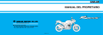
OWNER S MANUAL
HEAD OFFICE(FACTORY)
#58, SUNG SAN-DONG, CHANG WON, KYUNGNAM, KOREA
TEL: (82-55) 239-7000 / FAX: (82-2) 467-9997
IMPORTANT NOTICE
●
WELCOME
Thank you for purchasing an Daelim vehicle. We hope you enjoy safe riding.
●
OPERATOR AND PASSENGER
This motorcycle is designed to carry the operator and one passenger.
WARNING
Attempting to change the pre-set maximum speed may cause danger and will void the Daelim warranty.
●
●
ON-ROAD USE
This motorcycle is designed to be used only on the road.
READ THIS OWNER'S MANUAL CAREFULLY
Pay special attention to statements preceded by the following words:
WARNING
Indicates a strong possibility of severe personal injury or death if instructions are not followed.
CAUTION
Indicates a possibility of personal injury or equipment damage if instructions are not followed.
NOTE
Gives helpful information.
This manual is an important and integral part of your vehicle. keep it with your vehicle at all times, even though your vehicle is resold.
2007. 04 PRINTED
2007. 04 PUBLICATION
NO COPY
CONTENTS
HORN BUTTON ................................................................. 16
SPECIFICATION ...................................................................... 3
OPERATION INSTRUCTION .............................................. 4
EQUIPMENT USAGE ........................................................ 17
PRECAUTIONS .................................................. 4
STEERING LOCK .............................................................. 17
PRIOR TO STARTING VEHICLE ........................................ 5
SEAT .................................................................................. 17
CORRECT ATTIRE ............................................................. 5
HELMET HOLDER ............................................................ 18
OPERATION ........................................................................ 6
STORAGE COMPARTMENT ............................................ 18
CARGO ................................................................................ 7
SELF INSPECTIONS BEFORE OPERATION .......... 19
MODIFICATION ................................................................... 8
BRAKES ............................................................................ 19
ATTACHMENT .................................................................... 8
TIRES ................................................................................ 21
MUFFLER ............................................................................ 8
CLUTCH ............................................................................ 23
LOCATION.............................................................. 9
FUEL .................................................................................. 24
METER READING AND USAGE................................... 12
ENGINE OIL ...................................................................... 25
METER .............................................................................. 13
LIGHTS AND WINKER ...................................................... 25
TACHOMETER .................................................................. 13
BACK MIRROR .................................................................. 26
FUEL GAUGE .................................................................... 13
LICENSE PLATE ............................................................... 26
INDICATOR LAMPS .......................................................... 13
OPERATION ........................................................................ 26
MALFUNCTION INDICATOR LAMPS ............................... 13
PRE-RIDE INSPECTION ................................................... 26
SWITCH OPERATION ...................................................... 14
STARTING THE ENGINE .................................................. 27
MAIN SWITCH ....................................................................14
IF ENGINE CANNOT BE STARTED ................................. 28
KEYS ................................................................................. 15
RUNNING-IN ..................................................................... 28
HEADLIGHT ...................................................................... 15
RIDING .............................................................................. 29
STARTER BUTTON .......................................................... 16
BRAKING ........................................................................... 30
WINKER SWITCH ............................................................. 16
PARKING ........................................................................... 30
SAFETY
PARTS
1
2
MAINTENANCE .................................................................. 31
SAFE DRIVING....................................................................... 51
MAINTENANCE SCHEDULE ............................................ 32
PREPARATION BEFORE DRIVING ............................ 51
TOOL KIT ........................................................................... 34
DRIVING METHOD ............................................................ 52
FRAME AND ENGINE NUMBERS .................................... 34
DRIVING POSITION ...........................................................52
MAINTENANCE PRECAUTIONS ...................................... 35
PRECAUTION WHEN DRIVING ....................................... 53
THROTTLE OPERATION .................................................. 35
STARTING ......................................................................... 54
AIR CLEANER ................................................................... 36
TURNING METHOD .......................................................... 55
ENGINE OIL ...................................................................... 37
PRINCIPLE OF TURN ....................................................... 55
SPARK PLUG .................................................................... 38
EFFECT OF SPEED .......................................................... 55
DRIVE CHAIN .................................................................... 39
3 POSITIONS OF TURNING ............................................. 56
WHEEL REMOVAL ............................................................ 41
TURNING METHOD .......................................................... 57
BRAKE PAD WEAR ........................................................... 43
PRECAUTION WHEN TURNING ...................................... 58
SIDE STAND ..................................................................... 44
BRAKING METHOD .......................................................... 59
BATTERY .......................................................................... 45
BASIC PRINCIPLE OF BRAKE(FRICTION FORCE) ........ 59
FUSE REPLACEMENT ..................................................... 46
RESTRAINT OF BRAKE EFFECT (INERTIA) .................. 59
BULB REPLACEMENT ...................................................... 47
BRAKING METHOD .......................................................... 60
CABLE RUBBER PART ..................................................... 49
COMPARISION OF BRAKING DISTANCE ........................60
GENERAL CLEANING ...................................................... 49
IMPACT WHEN COLLISION ..............................................60
STORAGE GUIDE ............................................................. 50
WIRING DIAGRAM ............................................................... 62
SPECIFICATION
3
OPERATION INSTRUCTION
SAFETY PRECAUTIONS
This manual describes matters pertaining to correct operation,
safe operation and simple maintenance of the vehicle you
purchased.
To ensure more comfortable and safer operation,
make sure to read this manual carefully prior to operation.
The photographs and drawings shown in this manual may
differ from those of actual vehicles due to changes in vehicle
specifications and modifications made.
This vehicle is designed for 2 riders including the operator.
Do not use polluted gasoline.
Otherwse it cause rust inside the fuel tank, and
close the suppiy of fuel to the injector, leading to
an improper engine starting or may cause serious
damage to engine.
Do use genuine oil, then it will protect and extend
vehicle life.
Warranty does not apply to the motorcycles used in
competitions or competitive trials. No motorcycle
part may be tampered with, altered, or replaced with
parts other than original Daelim spare parts during the
warranty period.
As far as any defect caused by contaminated gasoline
or oil, the warranty will be automatically invalidated.
4
Careful driving and the wearing of proper attire and safety
equipment are the most important factors in the safe
operation of the daystar. Please obey traffic regulations and
do not be hurried and careless.
Many new vehicle owners operate their newly purchased
vehicles with great care and attention to safety factors.
However, after becoming accustomed to the operations are
often discarded, which can lead to accidents. Please don't let
this happen to you and always approach the operation of your
vehicle with the safety considerations needed.
When operating the vehicle, always keep in mind and obey
the notes of precaution printed on the Safety Precaution
Label attached to the vehicle.
Be sure to wear helmet at all time.
Be sure to put on gloves at all time.
Observe the speed regulations.
Beware of muffler affer driving as it is still hot to be burnt.
Especially never children touch on it.
For safety, do not change, alteration or modification the
vehicle.
Regularly conduct specified maintenance inspections.
<Maintenance Inspection Points>
Brakes, Tires, Oil, Lights, Horn, Instruments
PRIOR TO STARTING VEHICLE
CORRECT ATTIRE
Read user's manual carefully.
Conduct maintenance checks prior to operation.
Always maintain vehicle in clean status and carry out
specified maintenance checks.
Make sure to stop engine and stay away from fire when
fueling.
Exhaust gas contains harmful substance such as carbon
monoxide, Start engine in well-ventilated places.
Be sure you and your passenger always wear a helmet,
eye pretection and other protective apparel when you
ride.
Not wearing a helmet increases the chance of serious
injury or death in a crash.
5
OPERATION
Operators should naturally fix bodies to keep smooth driving.
Please check whether or not you are unnaturally strained and
strung up.
Driving pose has a great influence on safe operation.
Please always maintain the center of your body in the middle
of seat. Especially do not sit at the rear seat because it may
lessen the weight of front wheel and cause trembling steering
wheel.
When wanting to turn, slightly lean to body toward the
direction of the turn. It is unsafe if the body is not moved
in union with the motorcycle.
Curvy roads and poor, unpaved roads constantly change in
surface quality. Driving on these roads can be unsafe if
certain safety precautions are not followed.
In order to safely drive through these driving conditions,
anticipate coming road conditions, slow down to at least half
the normal speed, and relax your shoulders and wrists while
securely holding the handles.
Always hold the handle bars firmly with both hands
whiling driving, otherwise, it cause severe injury or death
of the driver. The pillion passenger should always hold
on to the operator with both hands and keep both feet on
the pillion step bar. otherwise, it cause severe injury or
death.
6
Pay attention not to overload goods and fasten it tightly
whiling driving.
Do not place kind of cloth materials nearby oil tank cap.
If the hole in oil tank cap is clogged, oil will not flow freely
into the engine which can cause severely engine damage.
Do not attach large or heavy items (such as a sleeping bag
or tent) to the handle bars, fork, or fender. Unstable
handling or sliw steering response may result.
7
MODIFICATION
Modification of vehicle structure or function deteriorates
manipulatability or causes exhaust noise to become louder
shortening the vehicle life. These modifications are not only
prohibited by law but also are the acts harmful to other
people. Modifications are not covered by warranty.
Improper accessories or modifications can cavse a crash
in which you can be seriously hurt or killed.
Follow all instruction in this owneris manual regarding
accessories and modifications.
MUFFLER
As far as any defect caused by modifications, the
warranty will be automatically invalidated.
Pay particular attention to fellow passenger so that he/she
can prevent getting burnt by the hot muffler during travel.
ATTACHMENT
Except designated attachment by DAELIM MOTOR CO.LTD.,
don’t attach any extra lighting device, because it may cause an
early discharging of battery.
Carefully inspect the accessory to make sure it does not obscure
any lights, reduce ground clearance and banking angle, or limit
suspension travel, steering travel or control operation.
Do not add electrical equipment that will exceed the motorcycle’s
electrical system capacity. A blown fuse could cause a dangerous
loss of lights or engine power.
This motorcycle was not designed to pull a sidecar or trailer.
Handling may be seriously impaired if so equipped.
8
Beware of muffler after driving as it is still hot to be
burnt. Especially never children touch on it. And pay
attention to park where pedestrian zoon.
If haystack or vinyl is stuck to the muffler, it might be
fired.
PARTS LOCATION
9
PARTS LOCATION
10
PARTS LOCATION
REAR CUSHION
HELMET HOLDER
RADIATOR
CALIPER
PILLION STEP BAR
BRAKE DISK
GEAR SHIFT PEDAL
MAIN STAND
SIDE STAND
MAIN STEP BAR
11
METER READING AND USAGE
12
MIL<MALFUNCTION INDICATION LAMP>
Indicates amount of gasoline in fuel tank.
If needle is within E mark,immediately fill
gasoline. Balance at this time is
approximately 4.0 litres.
To avoid running out of fuel,it might cause
serve injury due to engine abruptly stop.
Running the engine beyond recommended
maximum engine speed(the beginning of
the tachometer red zone)can damage the
engine.
EMS(Engine Management System)is
equipped with a self-diagnosis function
in order to ensure that the engine control
system is operation normally.
If this function detects a malfunction in
the system, the malfunction indicator
lamp immediately operates. It gives the
rider that malfunction has occurred in
the system.
Normally, the malfunction indicator
lamp illuminates for 3 seconds when the
main key is turned on. If the malfunction
indicator lamp does not come on under these
conditions, the malfunction indicator lamp
may be defective.
After 3 seconds, the malfunction indictor
lamp off automatically. However, the
MIL blinks continuously, check the EMS
system. If you are not able to check the
EMS system, contact your daelim dealers.
The EMS takes fail-safe function, it
enables to drive only temporary by
starting even on conditioned.
13
SWITCH OPERATION
Do not operate main switch key during
operation.
If the main switch key is placed on
Off or Lock position, all electrical
system will not function.
Never operate the main switch key
during travel as it might cause
unexpected accidents.
If it is necessary to remove the main
switch key, stop the vehicle first prior to
removing.
Prior to dismounting from the vehicle,
make sure to lock the steering wheel
and remove key.
If the key is left in “ON” position
without starting engine, battery is
discharged.
Do not use a number of keys together
with a metal key holder.
The keys and the key holder may
cause scratches or other damage to
the cover while operating the
vehicle.(Recommend cloth or leather
key holders)
14
15
16
EQUIPMENT USAGE
STEERING LOCK
To lock the steering, turn the handlebars
all the way to the left or right, turn the key
to LOCK while pushing in.
Remove the key.
To unlock the steering, turn the key to
OFF while pushing in.
SEAT
<FRONT SEAT>
To remove the front seat, insert the
ignition key into the seat lock.
Turn the ignition key counterclockwise,
and then pull the seat back and up.
To install the front seat, insert the tab into
the recess under the frame and push down
on the rear of the seat.
<REAR SEAT>
To remove the rear seat, remove both
front seat and center cover, remove the
seat mounting bolt, and then pull the seat
front and up.
To install the seat, insert the tab into the
recess under the frame and tighten the
mount bolt scurely.
WARNING
Do not turn the key to LOCK while
riding the vehicle driving.
17
18
SELF INSPECTIONS BEFORE OPERATION
19
Check that the fluid level is above the
LOWER level mark with the motercycle
in an upright position.
Brake fluid must be added to the reservoir
whenever the fluid level begins to reach
the LOWER level mark.
1. Remove the screws and master cylinder
cap, diaphragm plate, and diaphragm.
2. Fill the reservoir with recommended
brake fluid from a sealed container up
to the UPPER level mark.
RECOMMENDED BRAKE FLUID
is DOT3
3. Reinstall the diaphragm, diaphragm
plate, and master cylinder cap.
4. Tighten the screws securely.
Other checks :
Make sure there are no fluid leaks.
Check for deterioration or cracks in the
hose and fitting.
Check the brake pad for wear when
refilling with brake fluid.
20
[REAR BRAKE]
<REAR BRAKE FLUID LEVEL>
WARNING
Brake fluid may cause irritation.
Avoid contact with skin or eyes. In
case of contact, flush thoroughly with
water and call a doctor if your eyes
were exposed.
KEEP OUT OF REACH OF CHILDREN
CAUTION
When adding brake fluid, be very
careful not to allow foreign materials
to enter the reserve tank.
Do not fill past upper level.
This can cause brake fluid to leak out
of the reserve tank.
Do not let brake fluid contact vehicle
parts as this damages painted areas.
If oil contacts parts, quickly clean the
fluid off using a dry cloth.
Use recommended brake fluid as
other types can undergo chemical
changes.
21
22
CLUTCH
Clutch adjustment may be reguired if the
motorcycle stalls when shifting into gear
or tends to creep; or if the clutch slips,
causing acceleration to lag behind engine
speed.
Minor adjustments can be made with the
clutch cable adjuster at the lever.
CLUTCH LEVER FREE PLAY:10~20mm
<CLUTCH LEVER ADJUSTMENT>
1. Loosen the lock nut and turn the
adjuster. Tighten the lock nut and check
the adjustment.
2. If the adjuster is threaded out near its
limit or if the correct free play cannot
be obtained, loosen the lock nut and
turn in the cable adjuster completely.
Tighten the lock nut.
3. Loosen the lock nut at the lower end of
the cable. Turn the adjusting nut to
obtain the specified free play. Tighten
the lock nut and check the adjustment.
4. Start the engine, pull in the clutch lever
and shift into gear. Make sure the
engine does not stall and the motorcycle
does not creep. Gradually release the
clutch lever and open the throttle.
The motorcycle should begin to move
smoothly and accelerate gradually.
NOTE
If proper adjustment cannot be
obtained or the clutch does not work
correctly, see your Daelim dealer.
23
FUEL
<FUEL TANK>
The fuel tank capacity including the
reserve supply is : 15
To open the fuel fill cap;
1. Insert the ignition key and turn it
clockwise.
2. The cap is hinged and will lift up.
3. Do not overfill the tank. There should
be no fuel in the filler neck.
4. After refueling, to close the fuel fill
cap, push the cap into the filler neck
until it snaps closed and locks.
5. Remove the key.
24
WARNING
Gasoline is extremely flammable and
is explosive under certain conditions.
Refuel in a well-ventilated area with
the engine stopped. Do not smoke or
allow flames or sparks in the area
where gasoline is stored or where the
fuel tank is refueled.
Do not overfill the tank. After
refueling, make sure the fuel fill cap
is closed securely.
Avoid repeated or prolonged contact
with skin or breathing of vapor.
KEEP OUT OF REACH OF CHILDREN.
ENGINE OIL
<ENGINE OIL LEVEL CHECK>
Check the engine oil level each day before
riding the motorcycle.
The level must be maintained between the
upper and lower level marks on the oil
level gauge.
1. Start the engine and let it idle for a few
minutes.
2. Stop the engine and put the motorcycle
on its main stand on level ground.
3. After a few minutes, remove the oil
level gauge, wipe it clean, and reinsert
the gauge without screwing it in.
Remove the gauge. The oil level should
be between the upper and lower marks
on the oil level gauge.
4. If required, add the specified oil up to
the upper level mark.
Do not overfill.
5. Reinstall the oil level gauge.
Check for oil leaks.
LIGHTS AND WINKER
CAUTION
Running the engine with insufficient
oil pressure may cause serious engine
damage.
<HEADLIGHT, TAILLIGHT>
Start the engine and make sure the lights
turn on. Also check to see if the lights are
damaged or if there is dirt on them.
<BRAKE LIGHT CHECK>
Turn the main switch to ON.
While separately operating the front and
rear brakes, check to see if the brake light
turns on. Also check to see if there is any
damage to the lens or if there is dirt on the
brake light.
<WINKER CHECK>
Turn the main switch to ON.
Check to see if all the winker in the front
and rear of the vehicle (including left and
right sides) are flashing properly. At the
same time, check to make sure that the
automatic sound signal of the winker is
working. Check also to see if any of the
lens are damaged or dirty.
25
OPERATION
BACK MIRROR
Sit squarely on the seat and check to see if
you have a good view behind the vehicle
by looking at the back mirrors. Also check
for dirt and damage on the back mirrors.
LICENSE PLATE
Check to see if there is any dirt or damage
to the license plate.
Also check to see if the license plate is
firmly secured to the vehicle.
PRE-RIDE INSPECTION
WARNING
If the pre-ride inspection is not
performed, severe personal injury or
motorcycle damage may result.
Inspect your motorcycle every day before
you ride it. The items listed here will only
take a few minutes to inspect, and in the
long run they can save time, expense, and
possibly your life.
Check for signs of abnormality which
might have occurred on the previous
day.
Engine oil level - add engine oil if
required (page 25). Check for leaks.
Fuel level - fill fuel tank when necessary
(page 24). Check for leaks.
Front and rear brakes - check operation;
make sure that is no brake fluid leakage
(page 19~21).
Tires - check condition and pressure
(page 21~22).
Drive chain - check condition and slack
(page 39~40). Adjust and lubricate if
necessary.
26
Throttle - check for smooth opening
and full closing in all steering positions.
Lights and horn - check that headlight,
tail/brake light, turn signals, indicators
and horn function properly.
Side stand switch ignition cut-off
system - check for proper function
(page 44).
Angle rear view mirror.
CAUTION
Observe safety rules when conducting inspections.
Conduct inspections on a flat, solid
ground with the main stand erected.
If you are unable to correct trouble even
after you make adjustment or correction,
contact authorized maintenance shops,
dealers or designated repair shops for
necessary inspection and repairs.
STARTING THE ENGINE
Always follow the proper starting
procedure described below.
<PREPARATION>
Before starting, insert the key, turn the
ignition switch ON and confirm the
following:
The transmission is in NEUTRAL
(neutral indicator light ON)
This motorcycle is equipped with a side
stand ignition cut-off system. The
engine cannot be started if the side
stand is down, unless the transmission
is in neutral. If the side stand is up, the
Check to see if the MIL is illuminat for
engine can be started in neutral or in
3 second.
gear with the clutch lever pulled in.
After starting with the side stand down, <WHEN ENGINE IS COLD >
the engine will shut off if the
transmission is put in gear before
raising the side stand.
WARNING
2. Once engine is started, pull and release
throttle grip repeatedly to run engine
idle until engine is heated.
<WHEN ENGINE IS HOT >
1. Close throttle grip and press starter
button. (If engine is not started with 1-2
times trial.
2. If engine is not started with throttle grip
closed, open throttle grip approximately
1/8 to 1/4 and press starter button.
Never run the engine in an enclosed
area. The exhaust contains poisonous
carbon monoxide gas that can cause
loss of consciousness and lead to
death.
CAUTION
Do not keep the starter button
pressed for more than 5 seconds at a
time. Release the starter button for
approximately 10 seconds before
pressing it again.
1. Close throttle grip, and press starter
button.
27
IF ENGINE CANNOT BE STARTED
It is possible that starting will be more
difficult if the vehicle has not been used
for a long period of time or if the fuel
hole is plugged up (starting problems
even when there is sufficient fuel in the
fuel tank may be an indication of a
plugged fuel hole).
When this happens, do not rotate the
throttle grip and try the starter button a
few times.
NOTE
Do not run engine idle unreasonably.
This not only wastes fuel but also
adversely affects engine.
If starter button is pressed in gear
position, vehicle may bring out to
fall. Make sure gear is in neutral
position prior to starting engine.
If engine cannot be started or vehicle does
not move, check the followings.
Is there fuel in fuel tank?
Are you operating in accordance with
the instructions given in user's manual?
Is fuse not cut?
Is starter motor running?
If starter motor is not running due to
battery consumption, charge the battery.
If the MIL blinks continously when the
main key is on, inquiry to the daelim
dealer.
RUNNING-IN
During initial running-in newly machined
surfaces will be in contact with each other
and these surfaces will wear in quickly.
Running-in maintenance at 1,000km is
designed to compensate for this initial
minor wear.
Timely performance of the running-in
maintenance will ensure optimum service
life and performance from the engine.
The general rules as follows:
1. Never labour the engine with full
throttle at low engine speeds. This rule
is applicable not only during running-in
but at all times.
2. Maximum continuous engine speed
during the first 1,000km must not
exceed 5,000 rpm.
CAUTION
Running the engine beyond recommended maximum engine speed (the
beginning of the tachometer red
zone) can damage the engine.
28
RIDING
1. After the engine has been warmed up,
the motorcycle is ready for riding.
2. While the engine is idling, pull in the
clutch lever and depress the gearshift
pedal to shift into 1st (low) gear.
3. Slowly release the clutch lever and at
the same time gradually increase engine
speed by opening the throttle. Coordination of the throttle and clutch lever
will assure a smooth positive start.
4. When the motorcycle attains a moderate speed, close the throttle, pull in the
clutch lever and shift to 2nd gear by
raising the gearshift pedal.
This sequence is repeated to progressively shift to 3rd, 4th, 5th (top) gear.
5. Coordinate the throttle and brakes for
smooth deceleration.
6. Both front and rear brakes should be
used at the same time and should not be
applied strongly enough to lock the
wheel, or braking effectiveness will be
reduced and control of the motorcycle
be difficult.
<GEAR DOWN OPERATION>
If you gear down when you need to
drastically accelerate speed such as when
you are passing another motorcycle, speed
can be accelerated. If you ride too fast, it
adversely affects engine because engine
revolution is excessive.
23
1
45
GEAR CHANGE PEDAL
NOTE
Make sure side stand is in original
position prior to starting motorcycle.
If side stand moves unsatisfactorily,
check lubrication state on side stand
joint.
Shift gear adequately according to
vehicle speed.
To save fuel and maintain optimum
vehicle life, do not accelerate or
decelerate speed abruptly.
Always start in the 1" gear, and start
carefully as slow as possible.
If you hear abnormal noise during
travel, contact authorized maintenance shop immediately for
inspection and necessary action.
Maintain legal speed limits.
CAUTION
Touch pedal lightly with foot and
shift gear perfectly until you hear
"Click" at the pedal. If you apply
excessive force when shifting gear,
transmission may be damaged.
29
BRAKING
PARKING
1. For normal braking, gradually apply
both the front and rear brakes while
down shifting to suit your road speed.
2. For maximum deceleration, close the
throttle and apply the front and rear
brakes firmly.
WARNING
If you apply brakes only on front
wheel or rear wheel, vehicle may
slide off sideway and fall.
If you apply brakes abruptly during
travel in rain or on wet road, tires
slide off and may cause accidents.
Reduce speed and apply brake
cautiously.
Avoid repeated brake operation as it
may cause brake temperature to rise,
leading to braking effect deterioration.
When possible, reduce speed or
brake before entering a turn; closing
the throttle or braking in mid-turn
may cause wheel slip. Wheel slip
will reduce control of the motorcycle.
30
<ENGINE BRAKE>
If you turn throttle grip in reverse, engine
brake functions and, if you need stronger
braking, shift gear down from 4th to 3rd
and so forth. When you travel on a long
descent or on a sharp descent, use
intermittent braking technique and engine
brake simultaneously.
CAUTION
Do not shift to lower gear while
traveling at an excessive speed as it
may suddenly increase the engine
speed, adversely affect the engine
and transmission, and cause the rear
part of the vehicle to be shaken.
1. After stopping the vehicle, shift the
transmission into neutral, turn the fuel
cock OFF, turn the ignition switch OFF
and remove the key.
2. Put the vehicle on main stand and park
on level ground in places free of traffic.
3. Use the side stand to support the
vehicle while parked.
4. Turn the handlebar fully to the left and
lock the steering to help prevent theft.
CAUTION
Park the vehicle on firm, level ground
to prevent it from falling over.
Park in a safe area that will not block
traffic. When you parked the vehicle
after driving, make sure foot the
vehicle beyond man's reach because
engine and muffler are still hot.
If you must park on a slight incline,
aim the front of the vehicle uphill to
reduce the possibility of rolling off the
side stand or overturning.
MAINTENANCE
The Required Maintenance Schedule specifies how often you should have your motorcycle served, and what things need attention.
It is essential that your motorcycle be served as scheduled to retain its high level of safety, dependability, and emission control
performance.
These instructions are based on the assumption that the motorcycle will be used exclusively for its designed purpose. Sustained high
speed operation, or operation in unusually wet or dusty conditions, will require more frequent service than specified in the
MAINTENANCE SCHEDULE.
Consult your authorized Daelim dealer for recommendations applicable to your individual needs and use.
31
RIQUID THERMO CHECK
32
ODOMETER READING(NOTE 1)
FREQUENCY
1,000Km
1
4
8
12
16
MONTH
1
6
12
18
24
BRAKE FLUID
I
I
I
I
R
BRAKE SHOE / PAD WEAR
I
I
I
I
I
BRAKE SYSTEM
I
I
I
I
I
BRAKE STOP SWITCH
I
I
I
I
I
HEADLIGHT ADJUSTMENT
I
I
I
I
I
ITEM
SUSPENSION
CLUTCH
I
I
SIDE STAND
REMARK
NOTE( 3)
I
I
I
I
I
I
I
I
I
BOLTS, NUTS, FASTENERS
I
WHEELS / TIRES
I
I
I
I
I
I
I
STEERING HANDLE BEARING
I
I
I
I
I
If you do not have the appropriate tools or information to conduct maintenance, or if you feel you are not capable to perform
maintenance on this vehicle, inquiry to the authorized dealers or repair shops for maintenance and repairs.
To ensure safety, inspections and maintenance of these parts must be carried out by dealers, or repair centers.
NOTES : (1) At higher odometer readings, repeat at the frequency interval established here.
(2) Service more frequently when riding in unusually wet or dusty areas.
(3) Replace every 2 years, or at indicated odometer interval, whichever comes first. Replacement requires mechanical skill.
33
vjQRUfe
QPPPPQ
34
35
AIR CLEANER
When the element becomes dirty, there
will be greater intake resistance, resulting
in decreased power output and increased
fuel consumption.
The air cleaner should be serviced at
regular intervals (page 32).
Service more frequently when riding in
dusty areas.
CAUTION
Do not operate the engine without the
air cleaner element in place or severe
engine damage may result.
If you usually ride in dusty areas or
regularly operate in vehicle in wet,
muddy conditions, you must inspect
the air cleaner element more frequently than shown in the maintenance schedule.
If, at any time, the air cleaner
element is submerged in water,
immediately clean the element and
the inside of the air cleaner cover.
1. Remove the front seat (page 17)
2. Remove the air cleaner case cover by
removing the screws.
3. Remove the air cleaner inner pipe, and
remove the air cleaner element.
4. Replace the air cleaner element if it is
excessively dirty, torn or damage.
5. Install the air cleaner.
6. Install the removed parts in reverse
order of removal.
AIR CLEANER
INNER PIPE
AIR CLEANER
ELEMENT
CAUTION
If air cleaner element is inadequately
assembled, dust and other waste
materials are absorbed directly
inducing cylinder wear and output
deterioration, and adversely affecting
engine durability. Assemble correctly.
AIR CLEANER
CASE COVER
36
AIR CLEANER
CASE COVER
VJ125E
1000017
37
SPARK PLUG
If electrode is stained or plug gap is not
right, satisfactory spark is not produced.
Recommended plug :
-Standard : CR9EH-9
1. Remove the spark plug cover to remove
the spark plug.
2. Disconnect the spark plug cap from the
spark plug.
3. Clean any dirt from around the spark
plug base.
Remove the spark plug using the spark
plug wrench furnished in the tool kit.
4. Inspect the electrode and center
porcelain for deposits, erosion or cabon
fouling. If the erosion or deposit is
heavy, replace the plug. Clean a carbon
or wet-fouled plug with a plug cleaner,
otherwise use a wire brush.
5. Check the spark plug gap using a wiretype feeler gauge. If adjustment is
necessary, bend the side electrode
carefully.
The gap should be : 0.8~0.9mm
7. Tighten the spark plug 1/2 turn with a
spark plug wrench to compress the
washer.
8. Reinstall the spark plug cap and the
spark plug cover.
CAUTION
If plug of different maker or different
heat value is used, it causes
unsatisfactory engine starting,
inadequate engine revolution and
output deterioration.
The spark plug must be securely
tightened. An improperly tightened
plug can become very hot and
possibly damage the engine.
6. With the plug washer attached, thread
the spark plug in by hand to prevent
cross-threading.
38
To install a spark plug, turn it in as
far as possible with your fingers, then
tighten it with a wrench.
Do not overtighten or cross thread
the spark plug or the aluminum
threads of the cylinder head will be
damaged. Do not allow contaminants
to enter the engine through the spark
plug hole when the plug is removed.
39
<ADJUSTMENT>
Drive chain slack should be checked
and adjusted, if necessary, every
1,000km.
When operated at sustained high speeds
or under conditions of frequent rapid
acceleration, the chain may requir more
frequent adjustment.
1. Place the motorcycle on its main stand
with the transmission in neutral and the
ignition switch off.
2. Loose the axle nut.
3. Loose the lock nuts on both sides of the
swingarm.
4. Turn both adjusting nuts an equal
number of turns until the correct drive
chain slack is obtained. Turn the
adjusting nuts clockwise to tighten the
chain or counterclockwise to provide
more slack. Adjust the chain slack at a
point midway between the drive
sprocket and the rear wheel sprocket.
Rotate the rear wheel and recheck slack
at other section of the chain.
Chain slack should be : 10~20mm
40
CAUTION
ADJUSTING NUT
Excessive chain slack could cause
the chain to come off the sprockets,
resulting in loss of control or serious
engine damage.
Make sure the right and left chain
adjuster graduations are set in the
same position.
LOCK NUT
AXLE NUT
5. Tighten the axle nut to specified torque.
AXLE NUT TORQUE : 6.0~8.0kgf.m
6. Tighten the adjusting nuts lightly, then
tighten the lock nuts by holding the
adjusting nuts with a spanner.
7. Recheck drive chain slack.
WARNING
If a torque wrench is not used for this
installation, see your authorized dealer
as soon as possible to verify proper
assembly.
<LUBRICATION AND CLEANING>
Lubricate every 1,000km or sooner if
chain appears dry.
The O-rings in this chain can be damaged
by steam cleaning, high pressure washers,
and certain solvents. Clean the side
surfaces of the chain with a dry cloth. Do
not brush the rubber O-rings. Brushing
will damage them.
Wipe dry and lubricate only with SAE 80
or 90 gear oil. Commercial chain
lubricants may contain solvents which
could damage the rubber O-rings.
WHEEL REMOVAL
[FRONT WHEEL REMOVAL]
1. Raise the front wheel off the ground by
placing a support block under the
engine.
2. Loose the oval screw and remove the
speedometer cable.
3. Remove the front caliper assembly
from the fork by removing the fixing
bolts.
4. Loosen the axle nut.
AXLE NUT
FIXING BOLTS
BRAKE CALIPER
ASSEMBLY
NOTE
Do not depress the brake lever when
the wheel is off the motorcycle.
The caliper piston will be forced out
of the cylinder with subsequent loss
of brake fluid. If this occurs,
servicing of the brake system will be
necussary. See your authorized
Daelim dealer for this service.
5. Withdraw the front wheel axle, side
collar and remove the front wheel.
FRONT WHEEL AXLE
INSTALLATION NOTES:
Position the front wheel between the
fork legs and insert the axle from the
right side, through the left fork leg and
wheel hub.
CAUTION
When installing the wheel, carefully
fit the left brake disk between the
brake pads to avoid damaging the
pads.
Prior to assembling, align the projected
part( ) of the speedometer gear box
with the projected part of the left front
fork.
PROJECTED PART
OVAL SCREW
SPEEDOMETER
CABLE
41
Tighten the front axle nut to the
specified torque.
FRONT AXLE NUT TORQUE :
5.0~7.0kgf.m
Fit the caliper over the disk, taking care
not to damage the brake pads. Install
the caliper fixing bolts, and tighten to a
torque of : 2.7kgf.m
Install the speedometer cable and
tighten the oval screw.
[REAR WHEEL REMOVAL]
1. Place the motorcycle on its main stand
in upright position on level ground.
2. Loosen the drive chain adjusting nut
lock nuts and adjusting nuts.
3. Remove the rear axle nut.
4. Remove the drive chain from the driven
sprocket by pushing the rear wheel
forward.
ADJUST NUT
After installing the wheel, apply the
brake several times and then check if
the wheel rotates freely. Recheck the
wheel if the brake drags or if the wheel
does not rotate freely.
DRIVE CHAIN
42
AXLE SHAFT
NOTE
WARNING
WARNING
If torque wrench was not used for
installation, see you authorized dealer
as soon as possible to verify proper
assembly. Improper assembly may lead
to loss of braking capacity.
5. Remove the axle shaft, side collars and
rear wheel from the swing arm.
LOCK NUT
AXLE NUT
Do not depress the brake pedal while
the wheel is off the motorcycle.
The caliper pistons will be forced out
of the cylinders with subsequent loss
of brake fluid. If this occurs,
servicing of the brake system will be
nececcary. See your authorized
Daelim dealer for this service.
BRAKE PAD WEAR
INSTALLATION NOTES:
To install the rear wheel, reverse the
removal procedure.
Tighten the axle nut to the specified
torque.
REAR AXLE NUT TORQUE : 6.0~8.0kgf.m
Adjust the drive chain. (page 39)
CAUTION
CA
UTION
When installing the wheel, carefully
fit the left brake disk between the
brake pads to avoid damaging the
pads.
Brake pad wear depends upon the severity
of usage, the type of riding, and road
conditions. (Generally, the pads will wear
faster on wet and dirty roads.)
<FRONT BRAKE>
Inspect the pads at each regular
maintenance interval. (page 33)
[FRONT/REAR BRAKE]
Check the cutout in each pad.
If either pad is worn to the cutout,
replace both pads as a set.
See your authorized Daelim dealer for
this service.
CUTOUTS
<REAR BRAKE>
After installing the wheel, apply the
brake several times and then check if
the wheel rotates freely. Recheck the
wheel if the brake drags or if the wheel
does not rotate freely.
WARNING
WARNING
If torque wrench was not used for
installation, see you authorized dealer
as soon as possible to verify proper
assembly. Improper assembly may lead
to loss of braking capacity.
CUTOUTS
43
SIDE STAND
Erect main stand and place motorcycle
in upright position on level ground.
Check the spring for damage or loss of
tension and the side stand assembly for
freedom of movement.
Check the side stand ignition cut-off
system;
Put the side stand up.
Start the engine.
Lower the side stand. The engine
should stop as you put the side stand
down.
If the side stand system does not
operate as described, inspect it in the
closest authorized repair center.
44
BATTERY
BATTERY
It is not necessary to check the battery
electrolyte level or add distilled water as
the battery is a maintenance-free (sealed)
type. If your battery seems weak and/or is
leaking electrolyte (causing hard starting
or other electrical troubles), contact your
authorized Daelim dealer.
CAUTION
Removing the battery cap strip can
damage the cap strip and result in leaks
and eventual battery damage.
When the vehicle is to be stored for an
extended period of time, remove the
battery from the vehicle and charge it
fully. Then store it in a cool, dry place. If
the battery is to be left in the vehicle,
disconnect the negative cable from the
battery terminal.
WARNING
The battery gives off explosive gases;
keep sparks, flames, and cigarettes
away. Provide adequate ventilation
when charging or using the battery in
an enclosed space.
WARNING
Battery acid is poisonous and
corrosive. Avoid contact with eyes,
skin, clothing, and painted surfaces.
If battery acid comes in contact with
any of these, flush immediately with
large amounts of water.
If acid contacts the eyes or skin, get
medical attention.
KEEP OUT OF REACH OF CHILDREN.
Even though the battery is sealed, it
still vents explosive gases.
Do not allow open flames or sparks
near the battery.
<BATTERY REMOVAL>
1. Turn the ignition switch OFF.
2. Remove the front seat (page 17).
3. Remove the battery band.
4. Disconnect the negative
terminal lead
from the battery first, then disconnect the
positive terminal lead.
5. Pull out the battery from the battery box.
BATTERY BAND
CAUTION
Make sure that terminals do not contact
with other adjacent parts when handling
terminals.
<CLEANING BATTERY TERMINALS>
If the battery terminal is polluted, or in
rust, separate battery and clean it.
Battery terminal in rust with white
powder should be cleaned with warm
water. In case of serious rust of battery
terminal, disassemble the battery cord and
grind it with wirebrush or sandpaper.
45
FUSE REPLACEMENT
Turn off the main switch to see if the fuse
is severed. If the fuse is severed, exchange
the fuse into a fuse with same capacity.
Fuse is installed in fuse box around the
battery.
To change a fuse, first take off fuse
cover. Then, remove the disconnected
fuse, and insert the reserved fuse with
same capacity.
If the fuse immediately becomes
severed after being changed with the new
one, check another problem of the
electric system. Contact to Daelim
service center.
46
<DISASSEMBLY>
<ASSEMBLY>
Fuse A
Charging, combi S/W,
regulator, ECU
Fuse B
Winker relay, meter
lighting, horn, headlight
(LO/HI), front/rear stop
switch, taillight, fuel meter
heater control, water meter
Fuse C
Ignition coil
O2 Sensor, Stater
Fuse D
Fuel pump, ECU
Fuse E
pan motor
<NORMAL>
<DISCONNECT>
Do not use screw driver or other metal
parts to remove the fuse, as short circuit
can be occurred to cause damage to
electric system.
Do not usea fuse having a larger voltage,
as the wire can become overheated and
damaged.
When replacing any of the electrical
parts (lights and gauges), be sure to
replace them with the recommended
parts. Using different parts can lead to
the fuses burning out or damage to the
battery.
When washing the vehicle, take special
care not to allow to be splashed in the
area of the fuses.
BULB REPLACEMENT
Be sure to turn the ignition switch OFF
when replacing the bulb.
Do not use bulbs other than that
specified.
After installing a new bulb, check that
the light operates properly.
WARNING
WARNING
The light bulb becomes very hot while
the light is ON, and remain hot for a
while after it is turned OFF. Be sure to
let it cool down before servicing.
CAUTION
CA
UTION
Do not put finger prints on the
headlight bulb, as they may create
hot spots on the bulb and cause it to
break. Wear clean gloves while
replacing the bulb.
If you touch the bulb with your bare
hands, clean it with a cloth moistened
with alcohol to prevent its early
failure.
[HEADLIGHT BULB]
Before replacing the bulb, be sure to
check the switches for loose connection
of the connector.
1. Loosen the washer screws and remove
the headlight.
2. Pull off the socket without turning.
3. Loosen the pin and remove the bulb.
4. Install a new bulb in the reverse order
of removal.
[POSITION LIGHT BULB]
1. Pull the position light socket and
remove it.
2. Pull out the bulb without turning
3. Install a new bulb in the reverse order
of removal.
POSITION LIGHT BULB : 12V 5W
12V 35/35W
55W×× 2
HEADLIGHT BULB : 12V
SOKET
SCREW
BULB
BULB
WIRE
SCREW
HEADLIGHT UNIT
47
[STOP/TAILLIGHT BULB]
1. Loosen the screws and remove the
taillight lens.
2. Slightly press down on the bulb and
turn it counterclockwise.
3. Install a new bulb in the reverse order
of removal.
STOP/TAILLIGHT BULB : 12V 21/5W
[WINKER BULB]
<Front winker bulb>
1. Loosen the screw and remove the
winker lens.
2. Slightly press down on the bulb and
turn it counterclockwise.
3. Install a new bulb in the reverse order
of removal.
FRONT WINKER BULB : 12V10Wx2
<Rear winker bulb>
1. Loosen the screw and remove the
winker lens.
2. Slightly press down on the bulb and
turn it counterclockwise.
3. Install a new bulb in the reverse order
of removal.
REAR WINKER BULB : 12V10Wx2
SCREWS
SCREWS
SCREWS
48
CABLE RUBBER PART
A rubber part is assembled on the cable to
protect the inner cable.
Make sure that this part is placed firmly
around the correct part of the cable.
When washing the car, do not directly
spray water on to the rubber part is dirty,
use a dry cloth to clean this area.
GENERAL CLEANING
To preserve the finish of metal parts and
paintwork, wash and clean you rmotorcycle
at regular intervals, anyway according to
the road conditions you ride in.
Especially during winter period through
road salt a continuous cleaning of the
vehicle is necessary so that remove the road
salt. Use specific products only.
Avoid aggressive detergents or solents
RUBBER
<IMPORTANT>
Do not wash your motorcycle right after
use.When the motorcycle is still hot,
water drops will evaporate faster and
spot hot surfaces.
Do not use high pressure water jets.
Never aim the nozzle direct at wheel
bearings, front fork seals, electric items,
air inlets or exhaust pipe ends.
Clean off stubborn dirt or exceeding
grease from engine parts using a
degreasing agent.
Be sure to avoid contact with drive parts
(chain, sprockets, etc)
Rinse with warm water and dry all surfaces
with chamois leather.
CAUTION
Infiltration of the foreign materials or
water caused by damage of lever
(disengagement, tearing, etc.) may
cause freezing in winter season
resulting in faulty operation, sudden
accelation and braking force decrease.
If any damage is found, replace with
the new on immediately.
49
STORAGE GUIDE
Extended storage, such as for winter,
requires that you take certain steps to reduce
the effects of deterioration from non-use of
the motorcycle.
In addition, necessary repairs should be
made BEFORE storing the motorcycle;
otherwise, these repairs may be forgotten by
the time the motorcycle is removed from
storage.
<STORAGE>
1. Change the engine oil and filter.
2. Empty the fuel tank into an approved
gasoline container using a commercially
available hand siphon or an equivalent
method.
3. If storage will last more than one month,
carburetor draining is very important, to
assure proper performance after storage.
50
CAUTION
Gasoline is extremely flammable and
is explosive under certain conditions.
Perform this operation in a wellventilated area with the engine
stopped. Do not smoke or allow
flames or sparks in the area where
gasoline is drained or stored and
where the fuel tank is refueled.
4. Remove the battery. Store in an area
protected from freezing temperatures and
direct sunlight. Slow charge the battery
once a month.
5. Wash and dry the motorcycle. Wax all
painted surfaces.
6. Inflate the tires to their recommended
pressures. Place the motorcycle on
blocks to raise both tires off the ground.
7. Cover the motorcycle (don't use plastic
or other coated materials) and store in an
unheated area, free of dampness with a
minimum of daily temperature variation.
Do not store the motorcycle in direct
sunlight.
<REMOVAL FROM STORAGE>
1. Uncover and clean the motorcycle.
2. Change the engine oil if more than 4
months have passed since the start of
storage.
3. Charge the battery as required. Install the
battery.
4. Perform all Self Inspections Before
Operation checks (page 19).
Test ride the motorcycle at low speeds in
a safe riding area away from traffic.
SAFE DRIVING
PREPARATION BEFORE DRIVING
Performing daily inspection
Putting on the protective gears (Helmet, glove, goggles, etc.)
Bringing the driver's licence
Determinating the path to the desired destination
51
DRIVING METHOD
DRIVING POSITION
The appropriate driving position is most important thing to
driving safely.
Eyes : Look at the front direction widely.
Shoulders : Relieve the tension.
Arms : Relieve the tension and bend arms to inside and let
them act as the spring.
Hands : Grip the handle the position away from the inside
end of the handle with distance of one finger to
facilitate the operation of the switch and lever.
Wrist : Keep the state to act freely without applying excessive
force to the shoulder and arms.
Knees : Press the fuel tank slightly.
Feet : Place the feet to face the front parallel and make the
step bar be placed in the center of feet.
52
PRECAUTION WHEN DRIVING
Secure the safe distance.
Drive protectively.
Do not obstruct the traffic.
Do not drive on the pedestrian way or walkway.
Drive on the left driveway when passing away.
Make sure that you can apply the brake anytime.
Always apply the brake when stopping temporarily.
Do not drive excessively long distance and take enough
break.
If any abnormality is found, stop driving and contact service
center to inspect the vehicle.
Restart the vehicle after 2~3 min when it is turned over.
Always turn on the headlight at night.
53
STARTING
Prior to starting always look around to avoid accident.
Get on the vehicle after pulling back the stand.
Start driving slowly after turning on the winker and
releasing the brake while ensuring the safety around the
vehicle.
CAUTION
Return the side stand to its original position. Keep
driving without doing this may cause turnover accident.
Drive the vehicle only on the driveway. Driving on the
walkway can cause accident. Also, if the wheel is
transformed when advancing directly to the walkway, the
vehicle can be overturned resulting in injury of the driver
due to the driving unstability.
Overspeed driving on the unpaved road can cause the
vehicle to be overturned resulting in injury of the driver
due to the driving unstability.
Do not drive in the gravel road. If any gravel enters the
wheel or engine case, the vehicle can be overturned
resulting in injury of the driver.
If possible, do not drive close to the sea or on the road
where calcium chloride is treated.
The muffler, external parts and welded parts can be
corroded rapidly, and also in case of damage of the frame,
the vehicle can be overturned resulting in injury of the
driver.
54
TURNING METHOD
PRINCIPLE OF TURN
EFFECT OF SPEED
CENTRIFUGAL
FORCE
GRAVITY
The basic principle of turn is balancing using the centrifugal
force which makes vehicle go outside and the gravity which
makes vehicle fall inside.
The centrifugal force increases in inverse portion to the radius
of a curve and in portion to the square speed. Decelerate prior
to entering the curved way to reduce the centrifugal force.
55
3 POSITIONS OF TURNING
The basic principle of turn is balancing using combined force of
the centrifugal force and the gravity.
All 3 positions require straightening the head and keeping the
eyes horizontally.
< LEAN-WITH >
This is a turning position with motorcycle and driver in a line.
This position is the most natural and exact, so driver must learn
it thoroughly.
56
< LEAN-IN >
This is a turning position with driver leaned inside more than
motorcycle. This position is adequate to drive on the rained or
slippy road because it has best road holding.
However, special attention is required because front visual field
is poor when driver leans inside more than motorcycle.
TURNING METHOD
< LEAN-OUT >
This is a turning position with motorcycle leaned inside
more than driver, which is opposite to the lean-in position.
With this position, quick turn is well performed and driver can
obtain wide front visual field adequate to drive on the rained or
slippy road because it has best road holding. However, special
attention is required because there is danger of slipping on the
bad holding road.
Turn the throttle grip to its original position and decelerate
using both front and rear brakes.
Lean the vehicle toward inside of turn circle while driving
slowly at constant speed.
Accelerate gradually.
57
PRECAUTION WHEN TURNING
Do not drive inside of large truck's turn circle.
< DEAD ANGLE ZONE >
Dead angle zone is the sight range which cannot be identified by
driver and increases in proportion to the width of the vehicle.
58
< DISTANCE BETWEEN THE FRONT AND REAR WHEEL TURN >
It is distance between path of the front and rear wheel and
increases in proportion to the length of the vehicle.
BRAKING METHOD
BASIC PRINCIPLE OF BRAKE (FRICTION FORCE)
RESTRAINT OF BRAKE EFFECT (INERTIA)
Vehicle is braked using friction between road surface and
tires.
Braking distance increases 1.5 times on wet road and 3
times on icy road because friction force of road surface is
decreased.
NEW TIRE
NEW TIRE IN A
RAINY DAY
EXISTING
TIRE IN A
RAINY DAY
Due to the inertia, vehicle does not stop immediately after
applying the brake.
59
BRAKING METHOD
Turn the throttle grip to its original position and decelerate
using the engine brake.
Erect the vehicle straight.
Brake using both front and rear brakes.
IMPACT WHEN COLLISION
Learn the proper braking method to prevent accident.
COMPARISION OF BRAKING DISTANCE
Vehicle speed : 50 km/h
When using both front and rear brakes
When using only front brake
When using only rear brake
60
Impact increases in proportion to the speed and weight. The
impact when collision to concrete wall at 50 km/h is same
as one when falling from the height of 10m.
MEMO :
61
WIRING DIAGRAM
62
63
MEMO :
IMPORTANT NOTICE
●
WELCOME
Thank you for purchasing an Daelim vehicle. We hope you enjoy safe riding.
●
OPERATOR AND PASSENGER
This motorcycle is designed to carry the operator and one passenger.
WARNING
Attempting to change the pre-set maximum speed may cause danger and will void the Daelim warranty.
●
●
ON-ROAD USE
This motorcycle is designed to be used only on the road.
READ THIS OWNER'S MANUAL CAREFULLY
Pay special attention to statements preceded by the following words:
WARNING
Indicates a strong possibility of severe personal injury or death if instructions are not followed.
CAUTION
Indicates a possibility of personal injury or equipment damage if instructions are not followed.
NOTE
Gives helpful information.
This manual is an important and integral part of your vehicle. keep it with your vehicle at all times, even though your vehicle is resold.
2007. 04 PRINTED
2007. 04 PUBLICATION
NO COPY
OWNER S MANUAL
HEAD OFFICE(FACTORY)
#58, SUNG SAN-DONG, CHANG WON, KYUNGNAM, KOREA
TEL: (82-55) 239-7000 / FAX: (82-2) 467-9997