1
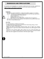
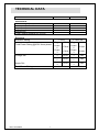
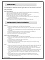
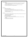
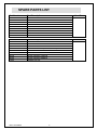
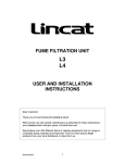
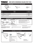
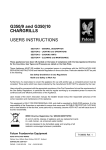
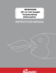
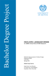
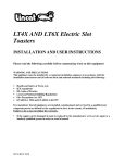
User, Installation and Servicing Instructions Opus 700 Electric Chargrills OE7405 and OE7406 IS421 ECN3592 Dear Customer, Thank you for purchasing this Lincat product. This is just one of over 450 different items of catering equipment available which is constantly being extended and improved. Details are available from your local distributor or direct from us. Used for the purposes for which it is intended, and with careful maintenance as outlined in this User Guide, your Lincat product will give you years of trouble free service. For use in GB & IE IMPORTANT INFORMATION Please read all of the safety and operating instructions carefully before using this product. Please pay particular attention to all sections of this User Guide that carry warning symbols and notices. WARNING! This is a Warning symbol. This symbol is used throughout the user guide whenever there is a risk of personal injury. Ensure that these warnings are read and understood at all times. CAUTION! This is a Caution symbol. This symbol is used throughout the user guide whenever there is a risk damaging your Lincat product. Ensure that these warnings are read and understood at all times. NOTE: This is a Note symbol. This symbol is used throughout the user guide to provide additional information, hints and tips. IS421 ECN3592 2 CONTENTS Contents Page Customer Information………………………………………………………. Warnings and Precautions………………………………………………… Technical Data……………………………………………………………….. Commissioning………………………………………………………………. Check List of Enclosures…………………………………………………... Installation…………………………………………………….……………… User………………………………………………………….………………….. Commissioning.…………………………………………………..…..……….. Servicing.…………………………………………………..………………….. Component Replacement …………………………….…………….……… Spare Parts List……..………………………………….…………………… Wiring Diagrams…………………………………..…………………………. Accessories............………………………………….……………………… Service information………………………………………………………….. Guarantee………………………………………………………….………….. IS421 ECN3592 3 2 4 5 6 6 7 8 9 11 11 13 14 16 17 17 WARNINGS AND PRECAUTIONS It is mandatory that all appliances are installed, commissioned and serviced by a qualified and competent person as defined by the regulations in force in the country of installation. Failure to comply will invalidate the warranty. WARNING! This appliance must be installed by a competent installation engineer in accordance with the installation instructions, and should conform to the following requirements: Local and National Building Regulations Fire Precautions Act Health & Safety At Work etc Act BS EN60335-1 Safety of Household and Similar Electrical Appliances After operation, some parts of the appliance will remain hot for a period of time. Please take care to avoid accidental burns. CAUTION! All equipment must be earthed to prevent shock. A means of disconnection must be incorporated in the fixed wiring having a contact separation of at least 3.0mm in all poles. Supply cords shall be oil-resistant, sheathed flexible cable not lighter than ordinary polychloroprene or equivalent synthetic elastomer-sheathed cord (code designation 30245 IEC 57) Connection of the electrical supply cable is made at the rear of the unit. Remove the protective cover and fit a suitable cable into the strain relief and then to the inlet terminal block. The unit is supplied for connection to a 230V three-phase supply. IS421 ECN3592 4 TECHNICAL DATA Model OE7405 OE7406 Dimensions Overall Height (mm) Width (mm) Depth (mm) Weight (kg) Total Cooking Surface w x d (mm) 455 600 810 20 550 x 525 455 900 810 62 845 x 525 11.2 kW Phase 3.73kW 1 Phase 3.73kW 2 Phase 3.73kW 3 Phase 16.2A 1 Phase 16.2A 2 Phase 16.2A 3 11.2 kW 2 x 8.25 kW Phase 5.5kW 1 Phase 5.5kW 2 Phase 5.5kW 3 Phase 24A 1 Phase 24A 2 Phase 24A 3 16.5 kW Electrical Element Rating Total Power Rating @ 400V three phase Voltage 3N~ Amps 3N~ Total Power Rating IS421 ECN3592 5 COMMISSIONING PREPARATION Remove all packaging and protective coatings prior to installation. The appliance is supplied as standard with adjustable feet. OE7405 OE7406 CHECK LIST OF ENCLOSURES Please ensure the following items are included with this piece of equipment: Model Steel scraper Slip stop washers Branding plates Splashguard Water level Indicator Legs Warranty Card User Instructions OE7405 1 2 4 1 1 4 1 1 OE7406 1 2 6 1 1 4 1 1 Tick SERIAL NUMBER NOTE Each appliance manufactured at Lincat has a unique identifying number found in the top right hand corner of the data plate attached at the rear of the appliance. Please record that number in the space provided should it be required for future reference. Serial Number MARK OF CONFIDENCE Every single product that leaves our factory bears a serial plate showing the assembler’s initials. It’s a mark of confidence we have in our people and our manufacturing process. IS421 ECN3592 6 INSTALLATION SITING The appliance must be installed in accordance with the appropriate regulations listed prior. The appliance should be installed on a level surface ensuring the unit is stable, firmly located and positioned to minimise the possibility of accidental touching. A clear space of at least 100mm must be left to the rear of the appliance to allow for servicing with a clear space of 600mm to the front to allow for safe operation. A minimum space of 100mm must be left between any side of the unit and any combustible surface or walls. Any partitions, walls or kitchen furniture in close proximity must be of non-combustible materials. ELECTRICAL SUPPLY AND CONNECTION Connection of the electrical supply cable is made at the rear of the unit. Remove the protective cover and fit a suitable cable into the strain relief and then to the inlet terminal block. The unit is supplied for connection to a 230V three-phase supply. Refer to schematics below. LEG HEIGHT ADJUSTMENT When the appliance has been installed in its intended position the legs should be adjusted to maintain a level top. A spirit level should be used to ensure that the appliance is level both left to right and front to back. This procedure is critical as it can affect the safety cut-out operation and will assist with the draining of the appliance. Anti slip washers are provided which can be screwed to the work surface to prevent movement during operation of the appliance. These create a slip free socket for the front feet. Ensure the work surface is structurally safe to screw through or into. ELEMENTS Elements are controlled by six position rotary switches, ‘6’ is the hottest. Off is indicated by a filled circle as shown in the control panel illustration on page 5. USER INSTRUCTION IS421 ECN3592 7 APPLIANCE USE This appliance is only for professional use and should only be used by qualified personnel. Ensure that the person responsible understands how to fill the water tank, safely operate, clean and shut down the appliance and is made aware of the position of the isolating switch in the event of an emergency. All users should know how to clean the branding plates and to fit them correctly in place. This appliance must not be used unattended. CONTROL PANEL A B C D Control Knob Drain Tap Safety Cut-out Reset Amber Neon E F G Power Neon Filler Valve Splashback G A MAINS POWER ON PAN SUPPORTS ON / OFF INDICATOR OVEN ELEMENT POWER ON HOB INDICATOR HOB FRONT CONTROL PANEL B F C E D OVEN THERMOSTAT CONTROL KNOB LH FRONT HOB LH REAR HOB MIDDLE FRONT HOB MIDDLE REAR HOB HOB CONTROL KNOBS HOB INDICATORS 1 2 3 4 5 6 OFF IS421 ECN3592 HIGH LOW 8 RH FRONT HOB RH REAR HOB COMMISIONING Operation of the Chargrill is by the control knobs on the fascia panel. When rotated clockwise the control knob provides power to the appropriate element. This appliance comes supplied with a water connection at the back. There is a an overflow pipe in case of accidental overfilling of the tank that must be connected to waste. Do not run this appliance without water in the tank the appliance must be operated with water between the level indicators. To fill the tank to the specified level the water valve at the front is opened anticlockwise. Close the valve as soon as the bottom level has been reached. If the appliance starts to over flow before the water level reaches the second leg of the level gauge the rear legs should be adjusted up. When the level has been reached remember to close the valve clockwise, do not over tighten. The appliance can be manually filled in emergencies and a funnel is supplied that attaches to the mains filler at the rear left of the unit. Due to the high temperatures that this appliance attains and the greater depth of our Opus appliances we do not recommend this as a regular way to use the equipment. Suitable PPE must be worn and the filling should be carried out carefully ensuring no overspill. NB: If the water level is not maintained the safety cut-out under the front of the fascia will operate. The appliance will then need resetting when it has cooled down. Frequent cutting out is an indication that the water level is not being maintained correctly. The amber neon will go out if the safety cut-out has tripped. When the appliance has cooled the red button on the cut-out can be can be pressed to reset it. When refilling after the appliance has overheated extreme caution should be advised as the cold water may react with the contents if they have been allowed to build up and become volatile. Preparation of the appliance Before using the appliance for the first time, ensure that all protective coating is removed from the unit. The branding plates should be washed and immediately dried with a clean cloth and coated with a thin film of cooking oil. This oil when heated by the elements will encourage a coating that resists rust. The appliance should be run to season the branding plates. During the lifetime of the appliance this coating process can be repeated whenever the coating has been removed. It will prevent rust on the cast iron grids. Do not put the branding plates into a decarboniser! OPERATION OF EITHER APPLIANCE Turn on the power supply at the isolating switch. The green neon will light indicating that mains power is on. The amber neon will indicate that the safety cut-out is set correctly. Turn the control knob to the required set point. The element will start to glow dull red if the knob is set to 6. At position 6 the element stays on constantly. Other positions will pulse the electricity to give less heat, however even though the elements may not glow they are still extremely hot and should be treated accordingly. OE7405 600mm CHARGRILL CONTROL Check the green ‘power on’ neon on the control panel is illuminated. Turn on the power supply at the isolating switch. The green neon will light indicating that mains power is on. The four branding plates create one large cooking zone. This is divided into three equal areas each area has its own control. Turn the control knob to the required set point. When the temperature reaches the selected set point, the element will cycle on and off to maintain the set temperature. Setting 6 remains on full and does not cycle. Each zone can be independently controlled between 1 and 6 The orange light will only go out if the safety stat detects that the water level is too low. OE7406 900mm CHARGRILL CONTROL Turn on the power supply at the isolating switch. The six branding plates create one large cooking zone. This is divided into six equal areas each area has its own control. NB: for additional safety this appliance has two cut-outs. Either cut-out will trip BOTH elements therefore if the appliance runs low and trips out check both safety thermostat reset buttons. The amber neon will be on only when both safety stats have been reset. Each zone can be independently controlled between 1 and 6. SHUT DOWN IS421 ECN3592 9 To turn the appliance off completely, rotate the control knob clockwise to the OFF position. Turn of the supply at the isolating switch. Turn off the water supply after cleaning. After operation, some parts of the appliance will remain hot for a period of time; care should be taken to avoid risk of burns. CLEANING Ensure the Electricity supply is isolated before commencing cleaning. All removable parts can be cleaned in a commercial dishwasher. Branding Plates After the appliance has cooled down to a safe level, remove the water level indicator, branding plates and splash guard then lift the element up ensuring the element stay is scurely latched. Any large pieces of food product should be removed. Warm soapy water can be poured into the tank to assist with the draining. Drain the tank into a bucket. Do not hang the bucket handle onto the tap. Clean the unit down with a warm detergent solution. Dry with a clean cloth. Do not use abrasive cleaners or any containing chlorine on stainless steel surfaces. Do not use a water jet to clean the appliance. Lift off each of the side liners from the unit. External surfaces can be cleaned using a cloth moistened with a warm detergent solution. For heavy, stubborn deposits a de-greasing agent ‘CARBON-OFF’ is available from Lincat upon request. NB. When the Branding Plates are dry lightly coat each one with cooking oil. When replacing parts that have been removed for cleaning, ensure that they are dry and observe correct relocation so as not to affect the performance and safety ofthe Chargrill. External Cleaning Do not use abrasives on stainless steel or enamelled parts. Do not use any products containing chlorine or hydrochloric acid to clean stainless steel surfaces. Do not clean the appliance using a water jet. IS421 ECN3592 10 SERVICING For information on authorised service agents please see the section at the end of these instructions. ROUTINE SERVICE 1. Carry out a general check of the installation paying particular attention to the following:2. Has the unit been installed using the correct supply cable? 3. Does the unit have separate isolation valves for water & electricity? 4. Is the connection to the supply via a suitable isolating switch? 5. Check all components for correct operation and replace where necessary, following the appropriate instructions. 6. Visually check the underside of the tank for any leaks 7. Ensure that all water carrying components are sound and free from leaks. COMPONENT REPLACEMENT Element 1. Remove the branding plates, level indicator and splash back. 2. Remove the two screws which secure the lifting box cover, then tilt the cover forward and lift away. 3. Remove the six nuts and disconnect the electrical terminals marking each to assist with reassembly. 4. Remove the four aero nuts that secure the element bracket to the lifting box. 5. Remove the element transfer the screws to the new element. 6. Reverse procedure above to reassemble appliance. Element cut-out switch in lifting box 1. Remove the branding plates, level indicator and splash back. 2. Remove the two screws which secure the lifting box cover, then tilt the cover forward and lift away. 3. Unscrew the screws, which secure the cut-out switch. 4. Transfer the wiring to the new switch. 5. Replacement is a reversal of the removal sequence, taking care not to trap the wiring harness whilst replacing the lid. Neon 1. Remove the drain tap nut access panel, undo the compression fitting, pull of the filling tap handle and the central blue pip which will eject smartly! Also remove the bezel. 2. Remove the screws securing the fascia panel to the base panel, remove the control knob and then hold the fascia panel at the bottom and rotate forward. 3. Protect the surrounding panel work with soft material and support the fascia panel against it. Access to the neon indicators is now possible. Remove the wires and unscrew the neon-retaining collar at the rear of the fascia. Withdraw the neon from the front of the fascia. 4. Remove and replace wires correctly, marking with an indelible pen if necessary. Replacement is a reversal of the removal sequence. Take care not to trap the wiring harness whilst replacing the fascia. IS421 ECN3592 11 Energy regulator 1. With the fascia panel removed as above disconnect the wires from the energy regulator terminals. It is easier to fit each wire to the new energy regulator as it is removed, therefore avoiding confusion. 2. Unscrew the M4 screws, which hold the energy regulator to the fascia panel. 3. Refit the energy regulator by reversing steps above. Safety stat 1. Remove fascia as above. 2. Remove the retaining safety stat screws 3. Loosen the phial retaining bracket nut sufficiently to gently remove the phial. 4. Replacement is a reversal of the removal procedure, taking care not to trap the wiring harness or the capillary. 5. Check the unit for electrical safety. Contactor 1. Turn off the water supply, opening and closing the filler tap will reduce the pressure in the supply pipe, remove the supply pipe. 2. Remove the overflow pipe. 3. Remove the back panel. 4. The contactor simply unclips from the bracket. 5. Transfer the wiring one wire at a time using a thin screwdriver to release the wiring clamps. 6. Refitting is the reversal of removal. 7. Check the unit for electrical safety. IS421 ECN3592 12 SPARE PARTS LIST Part Number BP37 CO167 CO214 EL273 EN10 KN233 NE39 NE40 VA05 Part Description BRANDING PLATE FILL VALVE CONTACTOR 11200 W ELEMENT ECO ENERGY REGULATOR OPUS KNOB PRINTED 1 TO 6 NEON LARGE GREEN NEON LARGE AMBER DRAIN VALVE Used On OE7405 Part Number BP37 CO167 CO214 EL272 EN10 KN233 NE39 NE40 VA05 Part Description BRANDING PLATE FILL VALVE CONTACTOR 8250W ELEMENT (2 REQUIRED) ECO ENERGY REGULATOR OPUS KNOB PRINTED 1 TO 6 NEON LARGE GREEN NEON LARGE AMBER DRAIN VALVE Used On OE7406 IS421 ECN3592 13 OE7405 Chargrill Wiring (E353) 25 24 23 18 17 13 7 8 14 19 6 9 CO214 5 EN10 10 EL273 15 AMBER NEONS 20 11 26 B 4 SW64 Earthed To Lifting Box B 22 B B 3 B 21 14 1 GREEN NEON 2 B 16 IS421 ECN3592 TE45 TH73 12 OE7406 Chargrill Wiring (E354 live & neutral shown separately) 6 X EN10 29 TH73 CO214 20 21 26 25 18 17 16 22 24 28 23 B EL272 TE45 27 B 31 19 15 B 30 EL272 3 4 TH73 12 7 14 1 2 CO214 8 6 11 9 13 2 x SW64 10 B B B 5 B 33 TH73 6 X EN10 32 CO214 48 47 EN45 EL272 34 35 AMBER NEONS 36 37 38 46 39 49 50 B Earths To lifting box tabs CO214 45 TH73 41 B 44 42 40 B EL272 IS421 ECN3592 43 GREEN NEON 15 Opus Floor Stand installation instructions OA7947 – 600mm wide Floor Stand & OA7948 – 900mm wide Floor Stand To fit the Chargrill to the above floor stand proceed as follows: 7. Remove feet from counter top unit. 8. Put 30mm packer on top frame side channels, taking care not to cover mounting holes and position unit on top. 9. Place the four ø22mm spacer tubes over the mounting holes on top frame side channels. 10. Insert four M10 x 50mm long hex socket screws through the mounting holes in the top frame (from underside). 11. Align bolts with nuts in the unit base, from which the counter top feet were removed, remove packers and tighten screws until the unit pulls up on the tubes. IS421 ECN3592 16 SERVICE INFORMATION Electric catering equipment should be routinely serviced to ensure a long trouble free life. It is recommended that this appliance is serviced every 6 months by a competent engineer. For help regarding the installation, maintenance and use of your LINCAT equipment, please call:- LINCAT SERVICE HELP DESK +44 (0) 1522 875520 AUTHORISED SERVICE AGENTS We recommend that all servicing other than routine cleaning be carried out by our authorised service agents. We cannot accept responsibility for work carried out by other persons. Please quote both the model and serial numbers from the data plate attached to the unit. Give brief details of the service requirement. If possible please quote the product code of the part number you require. Work carried out under warranty will normally be undertaken only during normal working hours, i.e. Monday to Friday, 8.30 a.m. - 5.00 p.m. CONDITIONS OF GUARANTEE The guarantee does not cover:1) 2) 3) Accidental breakage or damage Operational misuse, wear and tear from normal usage, incorrect adjustment, or neglect. Incorrect installation, maintenance, modification or unauthorised service work. IS421 ECN3592 17