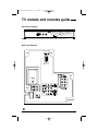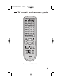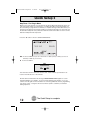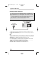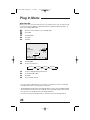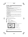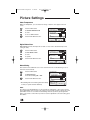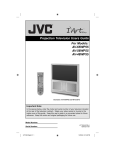
1
AV-36/32P903 English 6/18/02 9:23 AM Page 1 For models: AV-36P903 AV-32P903 COLOR TELEVISION USER'S GUIDE Illustration of AV-36P903 and RM-C324G IMPORTANT NOTE TO THE CUSTOMER In the spaces below, enter the model and serial number of your television (located at the rear of the television cabinet). Staple your sales receipt or invoice to the inside cover of this guide. Keep this user's guide in a convenient place for future reference. Keep the carton and original packaging for future use. Serial Number Model Number LCT1169-001A-A 0602-TN-FAA-JIM AV-36/32P903 English 6/18/02 9:23 AM Page 2 IMPORTANT SAFETY PRECAUTIONS CAUTION RISK OF ELECTRIC SHOCK DO NOT OPEN CAUTION:To reduce the risk of electric shock. Do not remove cover (or back). No user serviceable parts inside. Refer servicing to qualified service personnel. The lightning flash with arrowhead symbol, within an equilateral triangle is intended to alert the user to the presence of uninsulated “dangerous voltage” within the product’s enclosure that may be of sufficient magnitude to constitute a risk of electric shock to persons. The exclamation point within an equilateral triangle is intended to alert the user to the presence of important operating and maintenance (servicing) instructions in the literature accompanying the appliance. WARNING: TO PREVENT FIRE OR SHOCK HAZARDS, DO NOT EXPOSE THIS TV SET TO RAIN OR MOISTURE. CAUTION: TO INSURE PERSONAL SAFETY, OBSERVE THE FOLLOWING RULES REGARDING THE USE OF THIS UNIT. 1. Operate only from the power source specified on the unit. 2. Avoid damaging the AC plug and power cord. 3. Avoid Improper installation and never position the unit where good ventilation is unattainable. 4. Do not allow objects or liquid into the cabinet openings. 5. In the event of trouble, unplug the unit and call a service technician. Do not attempt to repair it yourself or remove the rear cover. Changes or modifications not approved by JVC could void the warranty. * When you don’t use this TV set for a long period of time, be sure to disconnect both the power plug from the AC outlet and antenna for your safety. * To prevent electric shock do not use this polarized plug with an extension cord, receptacle or other outlet unless the blades can be fully inserted to prevent blade exposure. AV-36/32P903 English 6/18/02 9:23 AM Page 3 IMPORTANT SAFEGUARDS CAUTION: Please read and retain for your safety. Electrical energy can perform many useful functions. This TV set has been engineered and manufactured to assure your personal safety. But improper use can result in potential electrical shock or fire hazards! In order not to defeat the safeguards incorporated in this TV set, observe the following basic rules for its installation, use and servicing. And also follow all warnings and instructions marked on your TV set. INSTALLATION 1 Your TV set is equipped with a polarized AC line plug (one blade of the plug is wider than the other). (POLARIZED-TYPE) This safety feature allows the plug to fit into the power outlet only one way. Should you be unable to insert the plug fully into the outlet, try reversing the plug. Should it still fail to fit, contact your electrician. 2 Operate the TV set only from a power source as indicated on the TV set or refer to the operating instructions for this information. If you are not sure of the type of power supply to your home, consult your TV set dealer or local power company. For battery operation, refer to the operating instructions. 3 Overloaded AC outlets and extension cords are dangerous, and so are frayed power cords and broken plugs. They may result in a shock or fire hazard. Call your service technician for replacement. 4 Do not allow anything to rest on or roll over the power cord, and do not place the TV set where power cord is subject to traffic or abuse. This may result in a shock or fire hazard. 5 Do not use this TV set near water — for example, near a bathtub, washbowl, kitchen sink, or laundry tub, in a wet basement, or near swimming pool, etc. 6 If an outside antenna is connected to the TV set, be sure the antenna system is grounded so as to provide some protection against voltage surges and built-up static charges. Section 810 of the National Electrical Code provides information with respect to proper grounding of the mast and supporting structure, grounding of the lead-in wire to an antenna discharge unit, size of grounding conductors, location of antenna discharge unit, connection requirements for the grounding electrode. IMPORTANT RECYCLING INFORMATION This product utilizes both a Cathode Ray Tube (CRT) and other components that contain lead. Disposal of these materials may be regulated in your community due to environmental considerations. For disposal or recycling information, please contact your local authorities, or the Electronic Industries Alliance: http://www.eiae.org AV-36/32P903 English 6/18/02 9:23 AM Page 4 7 An outside antenna system should not be located in the vicinity of overhead power lines or other electric light or power circuits, or where it can fall into such power lines or circuits. When installing an outside antenna system, extreme care should be taken to keep from touching such power lines or circuits as contact with them might be fatal. EXAMPLE OF ANTENNA GROUNDING AS PER NATIONAL ELECTRICAL CODE 8 TV sets are provided with ventilation openings in the cabinet to allow heat generated during operation to be released. Therefore: — Never block the bottom ventilation slots of a portable TV set by placing it on a bed, sofa, rug, etc. — Never place a TV set in a “built-in” enclosure unless proper ventilation is provided. — Never cover the openings with a cloth or other material. — Never place the TV set near or over a radiator or heat register. 9 To avoid personal injury: — Do not place a TV set on a sloping shelf unless properly secured. — Use only a cart or stand recommended by the TV set manufacturer. — Do not try to roll a cart with small casters across thresholds or deep pile carpets. — Wall or shelf mounting should follow the manufacturer’s instructions, and should use a mounting kit approved by the manufacturer. USE 10 Caution children about dropping or pushing objects into the TV set through cabinet openings. Some internal parts carry hazardous voltages and contact can result in a fire or electrical shock. 11 Unplug the TV set from the wall outlet before cleaning. Do not use liquid or an aerosol cleaner. 12 Never add accessories to a TV set that has not been designed for this purpose. Such additions may result in a hazard. AV-36/32P903 English 6/18/02 9:23 AM Page 5 13 For added protection of the TV set during a lightning storm or when the TV set is to be left unattended for an extended period of time, unplug it from the wall outlet and disconnect the antenna. This will prevent damage to product due to lightning storms or power line surges. 14 A TV set and cart combination should be moved with care. Quick stops, excessive force, and uneven surfaces may cause the TV set and cart combination to overturn. SERVICE 15 Unplug this TV set from the wall outlet and refer servicing to qualified service personnel under the following conditions: A. When the power cord or plug is damaged or frayed. B. If liquid has been spilled into the TV set. C. If the TV set has been exposed to rain or water. D. If the TV set does not operate normally by following the operating instructions. Adjust only those controls that are covered in the operating instructions as improper adjustment of other controls may result in damage and will often require extensive work by a qualified technician to restore the TV set to normal operation. E. If the TV set has been dropped or damaged in any way. F. When the TV set exhibits a distinct change in performance — this indicates a need for service. 16 Do not attempt to service this TV set yourself as opening or removing covers may expose you to dangerous voltage or other hazards. Refer all servicing to qualified service personnel. 17 When replacement parts are required, have the service technician verify in writing that the replacement parts he uses have the same safety characteristics as the original parts. Use of manufacturer’s specified replacement parts can prevent fire, shock, or other hazards. 18 Upon completion of any service or repairs to this TV set, please ask the service technician to perform the safety check described in the manufacturer’s service literature. 19 When a TV set reaches the end of its useful life, improper disposal could result in a picture tube implosion. Ask a qualified service technician to dispose of the TV set. 20 Note to CATV system installer. This reminder is provided to call the CATV system installer’s attention to Article 820-40 of the NEC that provides guidelines for proper grounding and, in particular, specifies that the cable ground shall be connected to the grounding system of the building, as close to the point of cable entry as practical. AV-36/32P903 English 6/18/02 9:23 AM Page 6 Table of Contents UNPACKING YOUR TV . . . . 7 ONSCREEN MENUS (Cont.) Connecting to Cable or an Antenna . . . . 13 Connecting to a Cable Box . . . . . . . . 13 Connecting to a Cable Box and VCR . . . 14 Connecting to a DVD Player, DTV Decoder and D-VHS . . . . . . . . . 15 Connecting to a Digital TV Receiver . . . 16 Connecting to an External Amplifier . . . 17 Connecting to a Camcorder . . . . . . . . 17 Connecting to JVC AV Compu Link III . . . 18 Sound Settings Bass . . . . . . . . . . . . Treble . . . . . . . . . . . Balance . . . . . . . . . . MTS (Multi-channel Sound) General Items On/Off Timer . . . . . . . . TV Speaker . . . . . . . . Audio Out . . . . . . . . . . Tilt Correction . . . . . . . Purity . . . . . . . . . . . . Closed Caption . . . . . . . Front Panel Lock . . . . . . Auto Shut Off . . . . . . . . XDS ID . . . . . . . . . . . Auto Demo . . . . . . . . . GETTING STARTED . . . . . . 19 BUTTON FUNCTIONS . . . . . 46 Remote Control Basics . . . . . . . Changing The Batteries . . . . . . . Setting Cable Box or Satellite Codes Setting VCR Codes . . . . . . . . Setting DVD Codes . . . . . . . . Menu. . . . . . . . . . . . . . . . . . Exit and PIP Off. . . . . . . . . . . . . Display . . . . . . . . . . . . . . . . . Video Status . . . . . . . . . . . . . . Sleep Timer . . . . . . . . . . . . . . . Muting . . . . . . . . . . . . . . . . . 100+ . . . . . . . . . . . . . . . . . . Return+. . . . . . . . . . . . . . . . . Input. . . . . . . . . . . . . . . . . . Light. . . . . . . . . . . . . . . . . . Sound . . . . . . . . . . . . . . . . . . Natural Cinema . . . . . . . . . . . . . 16:9 Mode . . . . . . . . . . . . . . . . Theater Pro . . . . . . . . . . . . . . . Index . . . . . . . . . . . . . . . . . . EZ Surf . . . . . . . . . . . . . . . . . VCR Buttons . . . . . . . . . . . . . . DVD Buttons . . . . . . . . . . . . . . TV/CATV Switch . . . . . . . . . . . . VCR/DVD Switch . . . . . . . . . . . PIP (Picture-In-Picture) . . . . . . . . . PIP/Move . . . . . . . . . . . Freeze. . . . . . . . . . . . Swap. . . . . . . . . . . . . Channel +/– . . . . . . . . . . Source. . . . . . . . . . . . TV models and remotes guide . 8 QUICK SETUP . . . . . . . . . 10 CONNECTIONS . . . . . . . . . 13 . . . . . . . . . . . . . . . 19 19 20 21 22 ONSCREEN MENUS . . . . . . 23 Using the Guide . . . . . . . . . . . . The Onscreen Menus . . . . . . . . . . Plug In Menu Instruction. . . . . . . . . Language. . . . . . . . . . Auto Tuner Setup . . . . . . Auto Clock Set . . . . . . . . Manual Clock Set . . . . . . Channel Summary . . . . . . . . . . . V-Chip. . . . . . . . . . . . . . . . . . Set Lock Code . . . . . . . . Picture Settings Tint . . . . . . . . . . . . . Color . . . . . . . . . . . . . Picture . . . . . . . . . . . . Bright . . . . . . . . . . . . Detail . . . . . . . . . . . . Color Temperature . . . . . . Digital Noise Clear . . . . . . Noise Muting . . . . . . . . . VSM . . . . . . . . . . . . . . Digital-In . . . . . . . . . . . . 23 . 23 . . . . . . . . 25 25 25 26 27 28 29 36 . . . . . . . . . . 37 37 37 37 37 38 38 38 39 39 . . . . . . . . 40 40 40 40 . . . . . . . . . . . . . . . . . . . . 41 42 42 42 43 43 44 44 44 45 . . . . . . . . . . . . . . . . . . . . . . . . . . 46 46 46 47 47 47 47 48 48 48 49 49 49 50 50 50 51 51 51 51 52 52 53 53 53 53 APPENDICES . . . . . . . . . . 54 Troubleshooting . . . . . . . . . Warranty . . . . . . . . . . . . . Authorized Service Centers . . . Search Codes . . . . . . . . . . Specifications . . . . . . . . . . . . . . . . . . . . . . . . . . . . . . . . . . . 54 55 57 58 59 AV-36/32P903 English 6/18/02 9:23 AM Page 7 Unpacking Your Television Thank you for your purchase of JVC’s model AV-36P903 or AV-32P903 Color Television. Before you begin setting up your new television, please check to make sure you have all of the following items. In addition to this guide, your television box should include: 1 Television 1 Remote Control TV CATV VCR DVD 16:9 MODE POWER INDEX MULTISCREEN/PIP CHANNEL PIP/MOVE INPUT SOURCE FREEZE DISPLAY 1 2 SLEEP TIMER 4 5 VIDEO STATUS 7 8 100+ 0 NATURAL CINEMA THEATER PRO SOUND SWAP 3 6 9 RETURN+ LIGHT EZ SURF RM-C324G MUTING V CHIP + CH VOL + VOL CH REW REC A matching TV stand is also available (optional). EXIT PIP OFF MENU VCR CHANNEL PREV NEXT 2 AA Batteries VCR/DVD POWER PLAY TV/VCR FF STOP PAUSE OPEN/CLOSE STILL/PAUSE TV Once you have unpacked your television, the next step is to connect it to your antenna/cable or satellite system and to connect the audio/video devices you want to use with your television. To make these connections you will use plugs like the ones illustrated below. RF Connectors A/V Input Plug Used to connect a coaxial cable from an external antenna or Cable TV system. Used to connect audio/video devices like VCRs, DVD players, stereo amplifiers, game consoles, etc. S-Video Plug Used to make video connections with VCRs, DVDs, Camcorders, etc (optional). AV Compu Link Cable Used to connect JVC AV Compu Link capable components for an automated home theater. We recommend that before you start using your new television, you read your entire User’s Guide so you can learn about your new television’s many great features. But if you’re anxious to start using your television right away, a quick setup guide follows on page 10 - 12. 7 AV-36/32P903 English 6/18/02 9:23 AM Page 8 TV models and remotes guide Front Panel Diagram OVER S VIDEO INPUT 4 VIDEO L MONO MENU AUDIO R CHANNEL VOLUME OPERATE NOTE: To open and close the front panel, gently push it until you hear a click. Rear Panel Diagram 8 AV-36/32P903 English 6/18/02 9:23 AM Page 9 TV models and remotes guide TV CATV VCR DVD 16:9 MODE POWER INDEX MULTISCREEN/PIP CHANNEL PIP/MOVE INPUT SOURCE DISPLAY 1 2 3 SLEEP TIMER 4 5 6 VIDEO STATUS 7 8 9 100+ 0 NATURAL CINEMA THEATER PRO SOUND FREEZE SWAP RETURN+ LIGHT EZ SURF RM-C324G MUTING V CHIP + CH VOL + VOL CH EXIT PIP OFF MENU VCR CHANNEL PREV NEXT REW REC VCR/DVD POWER PLAY TV/VCR FF STOP PAUSE OPEN/CLOSE STILL/PAUSE TV Remote Control RM-C324G 9 AV-36/32P903 English 6/18/02 9:23 AM Page 10 Quick Setup 1 Getting Started These quick setup pages will provide you, in three easy steps, with the basic information you need to begin using your new television right away. This information includes basic instructions on operating your remote control, making a simple cable/antenna and optional VCR connection and, finally, information on programming your television's Auto Tuner. If you have questions, or for more detailed information on any of these steps, please consult other sections of this manual. Step One - The Remote Control The remote control is the key to operating your television's many great features. Before you can operate your remote control, you first need to install the batteries (included). Slide the cover on the back of the remote down towards the bottom of the remote control. Insert two batteries (included) carefully noting the “+” and “–” markings, placing the “–” end in the unit first. Slide the cover back into place. Basic Operation Turn the television on and off by pressing the POWER button at the top right corner of the remote. POWER Power Button Key Feature Buttons The four key feature buttons at the center of the remote can be used for basic operation of the television. The top and bottom buttons will scan forward and back through the available channels. The right and left buttons will turn the volume up or down. These buttons are also marked with four arrows and are also used with JVC's onscreen menu system. You will need to use these buttons later in the Quick Setup. The next step is to connect your television to an antenna or cable. 10 Proceed to Step Two AV-36/32P903 English 6/18/02 9:23 AM Page 11 Quick Setup 2 Step Two - Making Basic Connections Next you will need to connect your television to an antenna, VCR or cable system. The most basic VCR and antenna/cable connection is shown below. For more detailed connections, such as ones where a cable box is required, or connecting with a combination of a cable box and VCR, home stereo system, etc., see pages 13 to 18. Cable/RF connector 1) Connect an RF Cable from the wall outlet into the RF Cable In on the back of the TV. Connecting to a VCR TV Rear Panel VCR IN OR OR 1) Connect the Red Cable from VCR Audio Output into the Red TV Audio In. 2) Connect the White Cable from VCR Audio Output into the White TV Audio In. 3) Connect the Yellow Cable from VCR Output into the Yellow TV Video In, OR Connect an RF Cable from VCR RF Cable Out into the RF Cable In on the back of the TV. NOTE: • White, Yellow and Red are the most common colors for VCR Cables. Some models may vary in color. Please consult the user’s manual for your VCR Player for more information. • See page 21 for instructions on programming your remote control to operate the basic functions of your VCR Player. Proceed to Step Three 11 AV-36/32P903 English 6/18/02 9:23 AM Page 12 Quick Setup 3 Step Three - The Plug In Menu When you turn your television on for the first time the Plug In Menu will appear. This menu sets some of the basic settings for your television. A complete description of the Plug In Menu can be found starting on page 25. We recommend you complete the Plug In Menu items before you start using your television. But to begin watching your television right away you only need to run the Auto Tuner Setup. This lets your television learn the channels it is able to receive. To run the Auto Tuner Setup follow the steps below. Press the button to move to AUTO TUNER SETUP ¥To choose CABLE (if you are connected to a cable system) or AIR (if you use an antenna) or SKIP (if you need to) To move to START NOW PROGRAMMING! 48 The Auto Tuner will now memorize all of the clear, active channels your television can receive. This will take one or two minutes. The Auto Tuner is finished when the message PROGRAMMING OVER! appears on screen. Your Quick Setup is now complete. You can now begin watching your television, or you can continue on in this guide for more information on connecting audio/video devices, programming your remote control, or using the JVC onscreen menu system to customize your television viewing experience. 12 STOP The Quick Setup is complete AV-36/32P903 English 6/18/02 9:23 AM Page 13 Connections Connecting to Cable or an Antenna There are three basic types of antenna or cable connections: • • • • • • If you have an antenna or have a cable system that does not require you use a cable box to select channels, please refer to Diagram #1. If you have a cable system that requires the use of a cable box to access all the channels, please refer to Diagram #2. If you have a cable system that requires the use of a cable box to access certain premium channels, but not “basic” cable channels, please refer to Diagram #3. For your convenience, connection to a VCR is also shown in the following diagrams. A VCR is not necessary for operation of the television or Picture-In-Picture (PIP) function. You may omit the VCR from your connections if you wish. For instructions on connecting a VCR only, please see the Quick Setup on page 11. For information on using PIP, please see page 52. Diagram #1 Cable/RF connector 1) Connect an RF Cable from the wall outlet into the RF Cable In on the back of the TV. Connecting to a Cable Box Diagram #2 1) Connect an RF Cable from the wall outlet into the RF Cable In on the Cable Box. 2) Connect an RF cable from the Cable Out on the cable box into the RF Cable In on the back of the TV. NOTE: • Please see page 52 for more information on using the PIP feature with a cable box. 13 AV-36/32P903 English 6/18/02 9:23 AM Page 14 Connections Connecting to a Cable Box and VCR Diagram #3 1) 2) 3) 4) 5) 6) Connect an RF Cable from the wall outlet into the RF Cable Box In. Connect an RF Cable from the Cable Box Out into the VCR In. Connect an RF Cable from the VCR Out into the RF In on the back of the TV. Connect the Red Cable from VCR Right Audio Output into the Red TV Audio In. Connect the White Cable from VCR Left Audio Output into the White TV Audio In. Connect the Yellow Cable from VCR Output into the Yellow TV Video In, OR Connect an S-Video Cable from VCR S-Video Out into the S-Video In on the back of the TV. NOTE: • White, Yellow and Red are the most common colors for VCR Cables. Some models may vary in color. Please consult the user’s manual for your VCR Player for more information. • See page 21 for instructions on programming your remote control to operate the basic functions of your VCR Player. The connection diagrams are intended to show some basic general connections. Some cable companies may require special connections to properly use your television or 2-tuner PIP function. If you follow these diagrams and either the television or PIP does not work properly, contact your local cable operator for more connection information. Please see page 52 for more information on the PIP feature. 14 AV-36/32P903 English 6/18/02 9:23 AM Page 15 Connections Connecting to a DVD player, DTV Decoder and D-VHS NOTE: This illustration is for connecting to Input 3 DVD Rear Panel AUDIO OUT R L Y PB PR Green Blue Red VIDEO OUT OR TV Rear Panel 1) Connect Green Cable Out from DVD Player “Y” Component Output into TV “Y” Component Input 2 or 3. 2) Connect Blue Cable Out from DVD Player “PB” Component Output into TV “PB” Component Input 2 or 3. 3) Connect Red Cable Out from DVD Player “PR” Component Output into TV “PR” Component Input 2 or 3. 4) Connect White Audio Cable Out from DVD Left Audio Output into TV Left Audio Input 2 or 3. 5) Connect Red Audio Cable Out from DVD Right Audio Output into TV Right Audio Input 2 or 3. 6) Connect the Yellow Cable Out from DVD Player Output into the Yellow TV In, OR connect an S-Video Cable from DVD Player S-Video Out into the S-Video In on the back of the TV. NOTE: • Green, Blue and Red are the most common colors for DVD Cables. Some models may vary in color. Please consult the user’s manual for your DVD Player for more information. • See page 22 for instructions on programming your remote control to operate the basic functions of your DVD Player. 15 AV-36/32P903 English 6/18/02 9:23 AM Page 16 Connections Connecting to a Digital TV Receiver TV Rear Panel Tighten screws after connections AUDIO OUT L R DIGITAL OUT DTV Decoder By inputting a High-bandwidth Digital Content Protection high-definition picture source to the Digital-In terminal of this television, high-definition pictures can be displayed on the screen in their digital form. (This terminal is for use in the future when High-bandwidth Digital Content Protection DTV decoders, DVD players and D-VHS are put on the market.) 1) Connect the DTV Digital RGB Output Terminal to the DIGITAL-IN Digital Input Terminal on the back of the TV. 2) Connect the Red Cable from the DTV Decoder Right Audio Output into the Right Audio Input. VCR Audio Output into the Red TV Audio In. 3) Connect the White Cable from the DTV Decoder Left Audio Output into the Left Audio Input. VCR Audio Output into the White TV Audio In. NOTE: • The Digital-In Terminal can only be used with 1080i and 720p and 480p picture signals. Set the DTV Decode Digital-Out Terminal Output setting to 1080i or 720p or 480p. For detailed information, refer to the DTV decoder instruction manual. If you cannot display the picture because your DTV decoder does not have a Digital-Out Terminal Output setting, use the component Video Input (or the S-Video Input or Video Input). (Refer to page 14 or 15.) In this case the picture will be displayed as an analog signal. • The Digital-In Terminal is not compatible with the picture signal of a personal computer. • Use a DVI 25-pin cable (commercially available) in order to digitally connect the TV with a DTV Decoder. • If the connection shown above is used, the DTV signal will be available on Digital-In on the Input Menu. (Refer to page 39.) If 480p signals (640 x 480 or 720 x 480) are displayed on the screen, the horizontal balance may be slightly shifted. In cases such as this, the horizontal balance can be adjusted by accessing “DIGITAL-IN” in the PICTURE ADJUST Menu. (Refer to page 39.) 16 AV-36/32P903 English 6/18/02 9:23 AM Page 17 Connections Connecting to an External Amplifier 1) Connect the White Audio Cable from the TV’s Left Audio Output Jack to the Amplifier’s Left Audio Input Jack. 2) Connect the Red Audio Cable from the TV’s Right Audio Output Jack to the Amplifier’s Right Audio Input Jack. NOTE: • See also “TV Speaker” and “Audio Out” on page 42 for more information on using external speakers. Connecting to a Camcorder You may connect a camcorder to your television by using the front Input Jacks (Input 4) located under the front panel door. To access, gently press on the door to open it. You may also connect a game console or other equipment using these jacks. Camcorders may also be connected to the television’s rear input jacks. OVER S VIDEO INPUT 4 VIDEO L MONO OR MENU AUDIO R CHANNEL VOLUME OPERATE Camcorder 1) Connect the Yellow Video Cable Out from the Camcorder’s Video Output into the TV’s Video Input Jack, OR connect an S-Video Cable from the Camcorder’s S-Video Output to the TV’s S-Video Input. 2) Connect the White Audio Cable Out from the Camcorder’s Left Audio Output into the TV’s Left Audio Input Jack. 3) Connect the Red Audio Cable Out from the Camcorder’s Right Audio Output into the TV’s Right Audio Input Jack. NOTE: • If your Camcorder is a mono sound model it will have only one audio jack. Connect it to the TV’s Left Audio jack. 17 AV-36/32P903 English 6/18/02 9:23 AM Page 18 Connections Connecting to JVC AV Compu Link III JVC’s AV Compu Link feature makes playing video tapes or DVDs totally automatic. Simply insert a pre-recorded tape into your JVC-brand VCR or DVD into your JVC DVD Player and the device will automatically turn on and begin playback. At the same time, using the AV Compu Link, the VCR or DVD player sends a signal to the television telling it to turn on and switch to the proper video input. • The AV Compu Link cable may be included with the JVC AV Compu Link accessory you wish to connect. If it is not, contact an authorized JVC Service Center for part # EWP 805-012. • AV Compu Link can only be used with JVC-brand products. 1) Plug one end of the AV Compu Link Cable into the AV Compu Link Input on your VCR, DVD, or other Compu Link device. 2) Plug the other end of the AV Compu Link Cable into the AV Compu Link Input at the rear of the TV. NOTE: • In order for the VCR playback to begin automatically, the recording tabs must be remove from the VHS tape. If the tab is in place, automatic switching will occur when you push the VCR’s Play button. • The AV Compu Link cable has a male 3.5 mm (mono) plug on each end. • If your JVC-brand VCR has “A Code/B Code Remote Control Switching” (see your VCR’s instruction book), using VCR A Code will switch the TV to Input 1. • To connect a JVC HiFi receiver or amplifier for a completely automated home theater, see the HiFi’s connection instructions for detailed connection information. • AV COMPU LINK III is compatible with any AV Compu Link III receiver. 18 AV-36/32P903 English 6/18/02 9:23 AM Page 19 Getting Started Remote Control Basics TV CATV VCR DVD 16:9 MODE POWER INDEX MULTISCREEN/PIP CHANNEL PIP/MOVE INPUT SOURCE FREEZE SWAP DISPLAY 1 2 3 SLEEP TIMER 4 5 6 VIDEO STATUS 7 8 9 NATURAL CINEMA 0 100+ THEATER PRO SOUND RETURN+ LIGHT EZ SURF RM-C324G MUTING CH • Press the CH+ and CH– buttons to scan through the channels. Tap the CH+ or CH– button to move through the channels one channel at a time. EXIT PIP OFF MENU REC • Slide the “VCR/DVD” selector switch to “VCR” to control a VCR. Slide to “DVD” to control a DVD player. Please see pages 20 to 22 for instructions on programming your remote control to operate a Cable Box, VCR or DVD player. • To move rapidly through the channels using JVC’s Hyperscan feature, press and hold CH+ or CH–. The channels will zip by at a rate of five channels per second. VOL + VOL REW • Press the POWER button to turn the television on or off. • Make sure the “TV/CATV” switch is set to “TV.” Move the switch to “CATV” only if you need to operate a cable box. V CHIP + CH VCR CHANNEL PREV NEXT • Before you can operate the remote control, you must first install the batteries (included). See “Changing the Batteries” at the bottom of this page for instructions. (For an illustration, please see page 10.) VCR/DVD POWER PLAY TV/VCR FF STOP PAUSE OPEN/CLOSE STILL/PAUSE TV • Press VOL+ or VOL– to raise or lower the volume. An indicator bar will appear onscreen to show you the television volume level. • The CH+/– and VOL+/– buttons are also used to navigate JVC’s onscreen menu system. • You can directly access specific channels using the 10-key pad. For more information on remote control button features, see pages 46 – 53. For information on using the onscreen menus, see page 23. Changing the Batteries Push down on the remote’s back cover and slide towards the bottom to remove it. Insert two AA batteries (supplied), carefully noting the "+" and "–" markings on the batteries and on the remote control. To avoid a potential short circuit, insert the "–" end first. Be sure to use only size AA batteries. When batteries are installed, slide the cover back into place (until it clicks into position). NOTE: • If the remote control acts erratically, replace the batteries. Typical battery life is six months to one year. We recommend using alkaline batteries for longer battery life. When you change the batteries, try to complete the task within three minutes. If you take longer than three minutes, the remote control codes for your VCR, DVD, and/or Cable Box may have to be reset. (See pages 20-22.) 19 AV-36/32P903 English 6/18/02 9:23 AM Page 20 Getting Started Setting the CATV, VCR and DVD Codes You can program your remote to operate your cable box, satellite receiver, VCR or DVD player by using the instructions and codes listed below. If the equipment does not respond to any of the codes listed below or to the code search function, use the remote control supplied by the manufacturer. Setting Cable Box or Satellite Codes The remote control is programmed with CATV and/or Satellite codes for power on, power off, channel up, channel down, and 10 key operation. 1) Find the CATV/Satellite brand from the list of codes shown below. 2) Slide the 2-way selector switch to “CATV”. 3) Press and hold down the DISPLAY button. 4) With the DISPLAY button held down, enter the first code number listed using the 10 key pad. 5) Release the DISPLAY button. 6) Confirm the operation of the Cable Box/Satellite receiver. • If your CATV or Satellite box does not respond to the first code, try the others listed. If it does not respond to any code, try the Search Codes Function, on page 58. Cable Box CODES ABC Archer 024 032, 025 Cableview 051, 032 Citizen Curtis Diamond 022, 051 058, 059 024, 032, 025 Eagle Eastern GC Brand 029 034 032, 051 022, 043 Gemini General Instrument 065, 024, 025, 026, 027, 020, 021, 022, 057, 023 Hamlin 040, 041, 042, 045, 058, 064 Hitachi 049, 024 Jerrold Macom CODES 032 RCA Realistic 061, 070 032 058, 064, 040, 041, 042, 045, 068 034 Regal Regency Rembrandt Samsung 037, 032, 051, 038 051 Digital Satellite Systems CODES Echostar 100, 113, 114, 115 Express VU 100, 113 G.E. 106 G.I. 108 Gradiente 112 Hitachi 104, 111 Scientific Atlanta 057, 058, 059 HNS (Hughes) 104 SLMark 051, 047 Panasonic 105 Sprucer 051, 056 Philips 102, 103 Stargate 032, 051 Primestar 108 Telecaption 067 Proscan 106, 109, 110 Teleview 047, 051 RCA 106, 109, 110 065, 024, 025, 026, 027, 020, 021, 022, 057, 023 Texscan 044 Sony 107 Tocom 035, 036, 066 Star Choice 104, 108 Toshiba 050 Toshiba 101 049, 050, 051, 054 Unika 032, 025 Uniden 102, 103 Universal 022, 032 Magnavox 033 Memorex Movietime 030 032, 051 Videoway 052 Viewstar 029, 030 Oak 039, 037, 048 Zenith 063, 046 Panasonic 055, 056, 060, 071, 073 063 Zenith/Drake Satellite 046 Paragon 20 Cable Box Puser Philips 028, 029, 030, 052, 053, 031, 069 Pioneer 047, 062 Pulsar 051, 032 AV-36/32P903 English 6/18/02 9:23 AM Page 21 Getting Started Setting VCR codes The remote control is programmed with VCR codes for power on, power off, play, stop, fast-forward, rewind, pause, record, channel up, and channel down operation. 1) Find the VCR brand from the list of codes shown below. 2) Slide the first 2-way selector switch to “TV” and the other 2-way selector switch to “VCR”. 3) Press and hold down the DISPLAY button. 4) With the DISPLAY button held down, enter the first code number listed with the 10 key pad. 5) Release the DISPLAY button. 6) Confirm the operation of the VCR. • If your VCR does not respond to the first code, try the others listed. If it does not respond to any code, try the Search Codes Function, on page 58. • Some manufacturer’s VCR’s may not respond to the TV/VCR button, even if other buttons work properly. • To record, hold down the REC button on the remote and press PLAY. VCRs CODES VCRs CODES VCRs CODES Admiral Aiwa 035 027, 032, 095 Marantz 003, 004, 005 Samsung Marta Memorex 064 024, 067 038, 040, 047, 048, 041, 042 058, 045, 093 037, 060, 062, 033, 089 089 029, 072, 073, 074 Audio Dynamic 003, 005 Bell & Howell 063, 071 Broksonic 020, 026, 094 Akai Canon CCE Citizen 023, 025 043 064 Craig Curtis Mathes 063, 029, 064 045, 024, 027, 093 043, 059, 024, 092 003, 004, 005 045, 093 Daewoo DBX Dimensia MGA Minolta Mitsubishi Multitech NEC Olympic Optimus Orion Panasonic Emerson 043, 026, 077, 061, 025, 042, 020, 076 Fisher 063, 066, 067, 065, 071, 091 Pentax Funai 027, 026, 020, 000 033, 045, 024 037, 051, 049, 050, 089 Philco G.E. Go Video Penney Philips Goldstar 064 Pioneer Gradiente 083, 084, 081, 000, 001 Proscan Hitachi 023, 045, 058, 027, 081, 093 Instant Replay 024, 023 Jensen 003 JVC 000, 001, 002, 003, 004, 005 Kenwood 003, 004, 064, 005 LXI 027, 064, 058, 065, 066, 063, 067 Magnavox 031, 023, 024, 086 Quasar Radio Shack RCA Realistic 038, 040, 047, 048, 041, 042, 078, 090 047, 027, 062 003, 004, 005, 000 024, 023 028, 021, 035, 064 026, 020 023, 024, 021, 022 024, 058, 045, 063, 003, 004, 005, 093 058, 005, 045, 093 031, 024, 027, 023, 026, 020, 043 031, 023, 024, 086 023 045, 058, 023, 024, 031, 046, 059, 060, 033, 087, 093 021, 022, 023, 024 033, 024, 063, 036, 067, 040, 027 033, 045, 058, 023, 024, 031, 046, 059, 060, 083, 084, 085, 087, 093 Samtron 003, 026, 020, 052 063, 067, 091, Sanyo 071 059, 060, 062, Scott 067, 038, 040, 047, 048, 026, 020 Sears 063, 064, 065, 066, 058, 000, 001 Shintom 075 Sharp 035, 036, 080, 088 Signature 2000 027, 035 Sansui Singer Sony 075 028, 029, 030, 053, 054, 055 SV 2000 Sylvania 027 031, 023, 024, 027 027, 081 Symphonic Tashiro Tatung Teac 064 003, 004, 005 003, 004, 027, 005 Technics 021, 022, 023, 024 024, 027, 070 059, 046, 079 Teknika Toshiba Vector Research 005 Wards Yamaha Zenith 035, 036, 067, 044, 064 063, 003, 004, 005 044, 082, 064, 094 024, 063, 036, 067, 040, 027 21 AV-36/32P903 English 6/18/02 9:23 AM Page 22 Getting Started Setting DVD codes The remote control is programmed with DVD codes for power on, power off, play, stop, fast-forward, rewind, previous chapter, next chapter, tray open/close, and still/pause operation. 1) Find the DVD Player brand from the list of codes shown below. 2) Slide the first 2-way selector switch to “TV” and the other 2-way selector switch to “DVD”. 3) Press and hold down the DISPLAY button. 4) With the DISPLAY button held down, enter the first code number listed with the 10 key pad. 5) Release the DISPLAY button. 6) Confirm the operation of the DVD player. • If your DVD player does not respond to the first code, try the others listed. If it does not respond to any code, try the Search Codes Function, on page 58. • After you program your remote, some DVD buttons may not work properly. If some buttons do not work properly, use the remote control which came with your DVD player. DVD Player 043 040 Denon Hitachi JVC Kenwood 020, 037 030, 031 000 035 Konka Mitsubishi Onkyo 039 025 041 Oritron Panasonic Philips Pioneer 044 020 023, 036 022 033 Raite 22 CODES Aiwa Apex DVD Player CODES RCA 021, 026 Sampo Samsung Sharp 034 030 028 Silvania Sony 038 Technics 020 Toshiba Vialta Wave Yamaha Zenith 023 050 042 020 027, 032 024, 045, 046, 047 AV-36/32P903 English 6/18/02 9:23 AM Page 23 Onscreen Menus Using the Guide Certain symbols are used throughout this guide to help you learn about the features of your new television. The ones you will see most frequently are: Up and Down arrows mean press the CH+ or CH– buttons. Pressing the CH+ or CH– buttons let you: • Move vertically in a main menu screen • Move through a submenu screen • Move to the next letter, number, or other choice in a submenu • Back up to correct an error • Scan through TV channels (when not in a menu screen) ¥ Left and right arrows mean press the VOLUME+ or VOLUME– buttons to move left or right to: • Select a highlighted menu item • Select an item in a submenu • Select numbers in certain menu options • Turn the volume up or down (when not in a menu screen) The “Press Button” icon means you should press the button named on your remote control. (Button names appear in SMALL CAPITAL LETTERS.) The Onscreen Menus To bring up the onscreen menu, press the MENU button on the remote control. The item that appears in yellow is the one currently selected. If you press the MENU button again, the onscreen display will skip to the next menu screen. If you use the Menu button on the TV’s front panel instead of the remote, an additional menu screen showing channel number and input will appear between “picture adjust” and “initial setup.” The “Plug In Menu” will appear the first time the TV is plugged in. INITIAL SETUP PREVIOUS Selected Option (Yellow) AUTO TUNER SETUP CHANNEL SUMMARY V-CHIP SET LOCK CODE AUTO DEMO ON OFF Selected Option (Blue) NEXT PAGE SELECT BY OPERATE BY EXIT BY EXIT NOTE: • Menus shown in this book are illustrations, not exact replications of the television’s onscreen displays. • The arrows on the next page show the order in which the onscreen menus appear when using the buttons on your remote or TV. 23 AV-36/32P903 English 6/18/02 9:23 AM Page 24 Onscreen Menus NOTE: • When you choose “THEATER” for Video Status, VSM does not appear. • Digital-In will display only when the 480p picture signal in Digital-In is displayed. PICTURE ADJUST PREVIOUS • Purity is for model AV-36P903 only. STANDARD TINT COLOR PICTURE BRIGHT DETAIL NEXT PAGE RESET BY EXIT BY SELECT BY OPERATE BY 0 EXIT PICTURE ADJUST PREVIOUS INITIAL SETUP PREVIOUS STANDARD COLOR TEMPERATURE AUTO TUNER SETUP LOW HIGH CHANNEL SUMMARY DIG. NOISE CLEAR NOISE MUTING ON OFF V-CHIP VSM ON OFF SET LOCK CODE DIGITAL-IN AUTO DEMO SIZE-1 SELECT BY OPERATE BY RESET BY EXIT BY 0 EXIT SELECT BY OPERATE BY EXIT PREVIOUS PREVIOUS BASS LANGUAGE TREBLE CLOSED CAPTION BALANCE STEREO SAP MONO ENG. FRAN. ESP. FRONT PANEL LOCK ON OFF AUTO SHUT OFF ON OFF XDS ID ON OFF NEXT PAGE NEXT PAGE SELECT BY OPERATE BY EXIT BY INITIAL SETUP SOUND ADJUST MTS ON OFF NEXT PAGE NEXT PAGE EXIT BY EXIT SELECT BY OPERATE BY EXIT BY EXIT INITIAL SETUP CLOCK/TIMERS PREVIOUS PREVIOUS SET CLOCK TV SPEAKER ON OFF ON/OFF TIMER AUDIO OUT VARI FIX TILT CORRECTION PURITY NEXT PAGE NEXT PAGE SELECT BY OPERATE BY 24 EXIT BY EXIT SELECT BY OPERATE BY EXIT BY EXIT AV-36/32P903 English 6/18/02 9:23 AM Page 25 Plug In Menu Introduction The Plug In Menu comes up automatically when you first turn on the TV after plugging it in. The Plug In Menu helps you to get your TV ready to use by letting you set your preferences for: • The Language in which you want the onscreen menus to appear • The Auto Tuner Setup of which channels you wish to receive • Setting the TV’s clock to the correct time so your timer functions will work properly Descriptions of each of the Plug In Menu features appear on this page and the next. We recommend you complete the Plug In Menu setup first so your TV is set up just the way you want, right away. Language You can choose to view your onscreen menus in three languages: English, French, or Spanish. Press the MENU button To LANGUAGE ¥ To choose a language ENGLISH FRENCH SPANISH • You will not need to press the MENU button to enter this screen from the Plug In Menu. Auto Tuner Setup In Auto Tuner Setup, the TV automatically scans through all available channels, memorizing the active ones and skipping over blank ones or channels with weak signals. This means when you scan (using the CHANNEL +/– buttons), you will receive only clear, active channels. Press the MENU button To AUTO TUNER SETUP ¥ ¥ To operate To choose CABLE or AIR (or SKIP) To move to START ¥ To start Auto Tuner Setup NOW PROGRAMMING ! 48 Programming will take approximately 1 to 2 minutes. PROGRAMMING OVER! • Noise Muting will not work during Auto Tuner Setup. • You will not need to press the MENU button to enter this screen from the Plug In Menu. • SKIP appears only for Plug-In menu. 25 AV-36/32P903 English 6/18/02 9:23 AM Page 26 Plug In Menu Auto Clock Set Before you use any of your TV’s timer functions, you must first set the clock. You may precisely set your clock using the XDS time signal broadcast by most Public Broadcasting stations. To set the clock using the XDS signal: Enter the channel number of your local PBS station Press MENU To SET CLOCK ¥ To operate ¥ To AUTO SET CLOCK AUTO ATLANTIC ON MODE T I ME ZONE D. S. T. FINISH SELECT BY OPERATE BY EXIT BY To TIME ZONE ¥ To select your time zone ATLANTIC EASTERN HAWAII EXIT CENTRAL ALASKA To move to Daylight Savings Time (D.S.T.) ¥ To turn D.S.T. ON or OFF To FINISH ¥ To save settings and exit MOUNTAIN PACIFIC • If you do not have a PBS station in your local area, you will have to set the clock manually. See ‘Manual Clock Set’ on the next page for instructions. • The Daylight Savings Time feature automatically adjusts your TV’s clock for Daylight Savings. The clock will move forward one hour at 2:00 am on the first Sunday in April. The clock will move back one hour at 2:00 am on the last Sunday in October. • You will not need to press the MENU button to enter this screen from the Plug In Menu. 26 AV-36/32P903 English 6/18/02 9:23 AM Page 27 Plug In Menu Manual Clock Set To set your clock manually (without using the XDS signal), choose MANUAL from the Set Clock menu and follow the steps below. To SET CLOCK ¥ ¥ To operate To MANUAL SET CLOCK MODE T I ME MANUAL : START CLOCK SELECT BY OPERATE BY To move to the hour ¥ To set the hour To move to minutes ¥ EXIT BY To set the minutes To move to START CLOCK ¥ To start clock and exit EXIT THANK YOU !! • You will not need to press the MENU button to enter this screen from the Plug In Menu. • You can change the preferences you set in the Plug In menu at any time using the regular JVC onscreen menu system. NOTE: You will have to reset the clock after a power interruption. You must set the clock before operating any timer functions. 27 AV-36/32P903 English 6/18/02 9:23 AM Page 28 Channel Summary Channel Summary Channel Summary allows you to customize the line-up of channels received by your TV. You can add or delete channels from the line-up or prevent any unauthorized viewers from watching any or all 181 channels. Press the MENU button To CHANNEL SUMMARY ¥ To operate CHANNEL SUMMARY CH NO. 01 02 03 04 05 SCAN √ √ √ CH NO. | | | | | SELECT BY OPERATE BY 06 07 08 09 10 SCAN √ √ √ EXIT BY EXIT The Channel Summary screen (above) will now be displayed with the channels set to scan marked with an " ". You can delete channels from the scan by removing the " ". If any channels were missed during Auto Tuner Setup and you wish to add them, you may by placing an " " next to the channel number. To the SCAN column ¥ To include or delete from scan EXIT/PIP OFF when finished You can block access to a channel by activating the Channel Lock. To CHANNEL SUMMARY ¥ To operate To the Lock Column ZERO to lock or unlock that channel EXIT/PIP OFF when finished Channel Guard Message When a viewer attempts to watch a guarded channel, the following message appears: THIS CHANNEL IS LOCKED BY CHANNEL GUARD. PLEASE ENTER LOCK CODE BY 10 KEY PAD TO UNLOCK IT. NO. - - - - To watch a channel that you have locked, enter the Lock Code using the 10 key pad. If the wrong code is entered, the message “INVALID LOCK CODE!” will flash on the screen. The channel cannot be accessed until the correct code is entered. • Once a channel has been unlocked, it will remain unlocked until the television is turned off. • See also “Set Lock Code”, page 36. 28 AV-36/32P903 English 6/18/02 9:23 AM Page 29 V-Chip Your TV is equipped with V-Chip technology which enables TV Parental Guidelines (for United States and Canada) and Movie (MPAA) Guideline controls. V-Chip technology allows you to program your TV to receive, or not to receive, programs based on content according to the guidelines. Programs which exceed the ratings limits you set will be blocked. When a viewer attempts to watch a blocked channel, this message appears: THIS PROGRAMMING EXCEEDS YOUR RATING LIMITS. PLEASE ENTER LOCK CODE BY 10 KEY PAD TO UNLOCK IT. NO. - - - The channel will remain blocked until the correct lock code is entered (see page 36 for information on setting your lock code). You can customize the V-Chip settings of your television to match your personal tastes. V-CHIP OFF V-CHIP SET US TV RATINGS SET MOVIE RATINGS SET CANADIAN RATINGS ENG SET CANADIAN RATINGS FRE UNRATED VIEW FINISH SELECT BY OPERATE BY EXIT BY EXIT The V-Chip menu above is the starting point for your V-Chip settings. You can use US V-Chip settings (for programming broadcast from the United States), Canadian V-Chip settings (for programming broadcast from Canada), and movie ratings. You may use any or all of the settings (US V-Chip, Canada V-Chip, Movie ratings). Descriptions for setting each of the three V-Chip formats appear in the next seven pages along with descriptions of the rating categories. To access the rating categories: Press the MENU button ¥ To V-CHIP To operate (Lock icon will appear) Press ZERO to access the V-Chip menu ¥ To turn V-Chip ON or OFF (V-Chip must be turned ON for rating settings to operate) To move to SET US TV RATINGS, SET MOVIE RATINGS, or SET CANADIAN RATINGS, (see following pages for descriptions of each item) Special Note about Ratings Some programs are not broadcast with a ratings signal. Therefore, even if you setup V-Chip ratings limits, these programs will not be blocked. Parents are cautioned to preview the contents of these programs or movies. 29 AV-36/32P903 English 6/18/02 9:23 AM Page 30 V-Chip US V-Chip Ratings U.S. PARENTAL RATING SYSTEMS Programs with the following ratings are appropriate for children. ❒ TV Y is Appropriate for All Children. Programs are created for very young viewers and should be suitable for all ages, including children ages 2 - 6. ❒ TV Y7 is for Older Children. Most parents would find such programs suitable for children 7 and above. These programs may contain some mild fantasy violence or comedic violence, which children should be able to discern from reality. Programs with the following ratings are designed for the entire audience. ❒ TV G stands for General Audience. Most parents would find these programs suitable for all age groups. They contain little or no violence, no strong language, and little or no sexual dialog or situations. ❒ TV PG Parental Guidance Suggested. May contain some, but not much, strong language, limited violence, and some suggestive sexual dialog or situations. It is recommended that parents watch these programs first, or with their children. ❒ TV 14 Parents Strongly Cautioned. Programs contain some material that may be unsuitable for children under the age of 14, including possible intense violence, sexual situations, strong coarse language, or intensely suggestive dialog. Parents are cautioned against unattended viewing by children under 14. ❒ TV MA Mature Audiences Only. These programs are specifically for adults and may be unsuitable for anyone under 17 years of age. TV MA programs may have extensive V, S, L, or D. Viewing Guidelines In addition to the ratings categories explained above, information on specific kinds of content are also supplied with the V-Chip rating. These types of content may also be blocked. The content types are: • • • • 30 V/FV is for VIOLENCE/FANTASY VIOLENCE S stands for SEXUAL CONTENT L stands for strong LANGUAGE D stands for suggestive DIALOG AV-36/32P903 English 6/18/02 9:23 AM Page 31 V-Chip Setting US V-Chip Ratings Press the MENU button ¥ To V-CHIP To operate (Lock icon will appear) Press ZERO to access the V-Chip menu V-CHIP OFF V-CHIP SET US TV RATINGS SET MOVIE RATINGS SET CANADIAN RATINGS ENG SET CANADIAN RATINGS FRE UNRATED VIEW FINISH SELECT BY OPERATE BY ¥ EXIT BY EXIT To turn V-Chip ON or OFF To move to SET US TV RATINGS ¥ To operate Directions to set US V-Chip Ratings: Line up the cursor in the column (TV PG, TV G, etc.) with the content row (V/FV, S, etc.) and press the or to move the cursor to the correct location. Press ¥ or to turn the locking feature on or off. An item is locked if the icon appears instead of a “—”. For example, to block viewing of all TV MA shows, move the cursor to the top row of that column and add a lock icon. Once you've put a lock on the top row, everything in that column is automatically locked. ¥ To the TV MA Column To turn on the lock SET US TV RATINGS TV MA TV 14 TV PG TV G TV Y7 TV Y V/FV S L D FINISH SELECT BY OPERATE BY EXIT BY To FINISH ¥ To save settings and exit EXIT • If you want to change the setup, move the cursor to the top column and change the lock icon to “—” by pressing ¥ or again. You may then select individual categories to block. 31 AV-36/32P903 English 6/18/02 9:23 AM Page 32 V-Chip Setting ratings with the V-Chip button To access Rating information about a certain program, press the V-CHIP button while viewing that program. A display like this will appear: PROGRAM IS RATED : TV-PG - V If you decide you want to block this category of viewing, press "0" while the above screen is visible, and all programs from that category will be blocked. Example 1: If you want to set your V-Chip settings to block all programming above TV PG: Press ZERO when TV-PG is displayed TV MA TV 14 TV PG TV G TV Y7 TV Y V/FV S L D All Programming above TV PG will be blocked. Example 2: If you want to set your V-Chip settings to block all programming above a current setting such as TV PG-V (with violence): Press ZERO when TV-PG - V is displayed TV MA TV 14 TV PG TV G TV Y7 TV Y V/FV S L D All Programming above TV PG - V (with Violence) will be blocked. • For Children's programming you can block TV-Y and Y7 programs by Pressing “0” when Y is displayed during a program. Programming for audiences other than children’s audiences will not be affected. 32 AV-36/32P903 English 6/18/02 9:23 AM Page 33 V-Chip Movie Ratings ❒ NR - Not Rated. This is a film which has no rating. In many cases these films were imported from countries which do not use the MPAA ratings system. Other NR films may be from amateur producers who didn’t intend to have their film widely released. NR (Not Rated) Programming may contain all types of programming including children's programming, foreign programs, or adult material. ❒ G – General Audience. In the opinion of the review board, these films contain nothing in the way of sexual content, violence, or language that would be unsuitable for audiences of any age. ❒ PG – Parental Guidance. Parental Guidance means the movie may contain some contents such as mild violence, some brief nudity, and strong language. The contents are not deemed intense. ❒ PG-13 – Parents Strongly Cautioned. Parents with children under 13 are cautioned that the content of movies with this rating may include more explicit sexual, language, and violence content than movies rated PG. ❒ R - Restricted. These films contain material that is explicit in nature and is not recommended for unsupervised children under the age of 17. ❒ NC-17 - No One Under 17. These movies contain content which most parents would feel is too adult for their children to view. Content can consist of strong language, nudity, violence, and suggestive or explicit subject matter. ❒ X - No One under 18. Inappropriate material for anyone under 18. Directions to set Movie (MPAA) Ratings: Press the MENU button ¥ To V-CHIP To operate (Lock icon appears) Press ZERO to access V-Chip setup options ¥ To SET MOVIE RATINGS To enter movies menu For example, SET MOVIE RATINGS X NC-17 R PG-13 PG G to block viewing of X and NC-17 rated from shows: ¥ To the X Column To turn on the lock To the NC-17 Column ¥ To turn on the lock To FINISH ¥ To save settings and exit NR FINISH SELECT BY OPERATE BY EXIT BY EXIT 33 AV-36/32P903 English 6/18/02 9:23 AM Page 34 V-Chip Canadian V-Chip Ratings ❒ E - Exempt. Exempt programming includes: news, sports, documentaries and other information programming, talk shows, music videos, and variety programming. ❒ C – Programming Intended for Children. Violence Guidelines: There will be no realistic scenes of violence. Depictions of aggressive behavior will be infrequent and limited to portrayals that are clearly imaginary, comedic or unrealistic in nature. ❒ C8+ – Programming Intended for Children 8 and Over. Violence Guidelines: Any realistic depictions of violence will be infrequent, discreet, of low intensity and will show the consequences of the acts. There will be no offensive language, nudity or sexual content. ❒ G – General Audience. Programming will contain little violence and will be sensitive to themes which could affect younger children. ❒ PG - Parental Guidance. Programming intended for a general audience, but which may not be suitable for younger children. Parents may consider some content not appropriate for children aged 8-13. ❒ 14+ - 14 Years and Older. Parents are strongly cautioned to exercise discretion in permitting viewing by pre-teens and early teens. Programming may contain mature themes and scenes of intense violence. ❒ 18+ - Adult. Material intended for mature audiences only. Directions to set Canadian V-Chip Ratings: Press the MENU button ¥ To V-CHIP To operate (Lock icon appears) Press ZERO to access V-Chip setup options ¥ To SET CANADIAN RATINGS ENG (for English) To enter ratings menu For example, SET CANADIAN RATINGS ENG 18+ 14+ PG G C8 to block viewing of programming rated 14+ and 18+ : To the 18+ Column C FINISH SELECT BY OPERATE BY EXIT BY EXIT ¥ To turn on the lock To the 14+ Column ¥ To turn on the lock To FINISH ¥ To save settings and exit • For instructions on “Set Canadian Ratings FRE (in French)”, please see page 34 in the French side of this user’s guide. 34 AV-36/32P903 English 6/18/02 9:23 AM Page 35 V-Chip Unrated Programs Notes About Unrated Programs: Unrated programming refers to any programming which does not contain a rating signal. Programming on television stations which do not broadcast rating signals will be placed in the “Unrated Programming" category. Examples of Unrated programs: Emergency Bulletins Locally Originated Programming News Political Programs Public Service Announcements Religious Programs Sports Weather Some Commercials • TV programs or movies that do not have rating signals will be blocked if the Unrated Category is set to BLOCK. Directions to Block Unrated Programs: You can block programs that are not rated. Press the MENU button To V-CHIP ¥ To operate (The lock icon appears) Press ZERO to access V-Chip setup options To UNRATED UNRATED ¥ ¥ VIEW To VIEW or BLOCK Press EXIT/PIP OFF when done 35 AV-36/32P903 English 6/18/02 9:23 AM Page 36 V-Chip Set Lock Code Channel Guard and V-Chip settings are protected by a four-digit Lock Code. Your TV comes pre-set with a Lock Code of "0000". You may change the code to any four-digit number you wish. To change the Lock Code, follow the steps below. Press the MENU button To SET LOCK CODE ¥ To operate The lock icon appears Press ZERO to access the Lock Code SET LOCK CODE LOCK CODE 0000 FINISH SELECT BY OPERATE BY EXIT BY EXIT The first digit will be highlighted ¥ To select the number To move to the next digit Continue to follow these directions for all four numbers To FINISH ¥ To save settings and exit Your Lock Code is now set. NOTE: • After a power interruption you must reset the Lock Code. • Write your Lock Code number down and keep it hidden from potential viewers. • If you forget the Lock Code, a new code may be set using the steps listed above. 36 AV-36/32P903 English 6/18/02 9:23 AM Page 37 Picture Settings Tint Tint allows you to adjust the levels of red and green in your TV picture. Press the MENU button ¥ To TINT To increase the levels of green To increase the levels of red To move to the next setting Color The color function lets you make all the colors in the TV picture appear either more vivid or subtle. Press the MENU button ¥ To COLOR To make the colors more vivid To make the colors more subdued To move to the next setting Picture Picture allows you to adjust the levels of black and white on the TV screen, giving you a darker or brighter picture overall. Press the MENU button ¥ To PICTURE To increase the level of contrast To decrease the level of contrast To move to the next setting Bright You can adjust the overall brightness of the TV picture with the Bright control. Press the MENU button ¥ To BRIGHT To lighten the picture To darken the picture To move to the next setting Detail The Detail feature adjusts the level of fine detail displayed in the picture. Press the MENU button ¥ To DETAIL To make the picture sharper (more details) To make the picture smoother (less detail) To move to the next setting 37 AV-36/32P903 English 6/18/02 9:23 AM Page 38 Picture Settings Color Temperature With Color Temperature, you can decide how strong or dull, the colors appear on the TV screen. Press the MENU button PICTURE ADJUST PREVIOUS ¥ ¥ To COLOR TEMPERATURE To enter To choose LOW or HIGH Press EXIT/PIP OFF when done STANDARD COLOR TEMPERATURE LOW HIGH DIG. NOISE CLEAR NOISE MUTING ON OFF VSM ON OFF DIGITAL-IN SIZE-1 NEXT PAGE SELECT BY OPERATE BY RESET BY EXIT BY 0 EXIT Digital Noise Clear With Digital Noise Clear, this helps take out static or noise from a channel that may not be coming in clearly. Press the MENU button ¥ ¥ PICTURE ADJUST PREVIOUS To DIG. NOISE CLEAR To enter To operate Press EXIT/PIP OFF when done STANDARD COLOR TEMPERATURE LOW HIGH DIG. NOISE CLEAR NOISE MUTING ON OFF VSM ON OFF DIGITAL-IN SIZE-1 NEXT PAGE SELECT BY OPERATE BY RESET BY EXIT BY 0 EXIT Noise Muting This feature inserts a blank blue screen over channels which are not broadcasting or are too weak to be received clearly. Press the MENU button PICTURE ADJUST PREVIOUS ¥ To NOISE MUTING To turn Noise Muting ON or OFF Press EXIT/PIP OFF when done STANDARD COLOR TEMPERATURE LOW HIGH DIG. NOISE CLEAR NOISE MUTING ON OFF VSM ON OFF DIGITAL-IN SIZE-1 NEXT PAGE • Noise Muting will not work during Auto Tuner Setup or when you operate Channel Summary. SELECT BY OPERATE BY EXIT BY EXIT NOTE: The setting screen will disappear if you do not make any adjustments or move to the next setting in approximately three seconds. Any changes you have made to picture settings up to that point will be stored. You can exit the Picture Settings menu at any time by pressing the EXIT button on the remote control. When you want to reset the adjustment as the start setting, press the 0 button. 38 AV-36/32P903 English 6/18/02 9:23 AM Page 39 Picture Settings VSM (Velocity Scan Modulation) Velocity Scan Modulation circuitry varies the electron beam's horizontal scanning speed to help accentuate the differences in picture brightness to sharpen the edges of images. Press the MENU button PICTURE ADJUST PREVIOUS ¥ ¥ To VSM To enter To turn VSM ON or OFF Press EXIT/PIP OFF when done STANDARD COLOR TEMPERATURE LOW HIGH DIG. NOISE CLEAR NOISE MUTING ON OFF VSM ON OFF DIGITAL-IN SIZE-1 NEXT PAGE • When you select “THEATER” for Video Status, VSM does not appear on the menu. SELECT BY OPERATE BY RESET BY EXIT BY 0 EXIT Digital-In This is for if you are able to receive digital broadcasts. Press the MENU button PICTURE ADJUST PREVIOUS ¥ ¥ To DIGITAL-IN To enter To choose DIGITAL-IN SIZE-1 or SIZE-2 Press EXIT/PIP OFF when done • Digital-In will display only when the 480p picture signal in Digital-In is displayed. STANDARD COLOR TEMPERATURE LOW HIGH DIG. NOISE CLEAR NOISE MUTING ON OFF VSM ON OFF DIGITAL-IN SIZE-1 NEXT PAGE SELECT BY OPERATE BY RESET BY EXIT BY 0 EXIT 39 AV-36/32P903 English 6/18/02 9:23 AM Page 40 Sound Settings Bass You can increase or decrease the level of low-frequency sound in the TV’s audio with the Bass adjustment. Press the MENU button ¥ To BASS To increase the bass To decrease the bass To move to the next setting Treble Use Treble to adjust the level of high-frequency sound in your TV’s audio. Press the MENU button ¥ To TREBLE To increase the treble To decrease the treble To move to the next setting Balance Adjust the level of sound between the TV’s two speakers with the Balance setting. Press the MENU button ¥ To BALANCE To shift the balance towards the right speaker To shift the balance towards the left speaker To move to the next setting MTS (Multi-Channel Television Sound) MTS technology allows several audio signals to be broadcast at once, giving you a choice in what you wish to hear with a TV program. In addition to mono or stereo sound, an MTS broadcast may also include a Second Audio Program (SAP). Press the MENU button To MTS ¥ Select the mode (The ON AIR arrow tells you if a broadcast is in Stereo and/or contains an SAP). • Keep the TV in STEREO mode to get the best sound quality. The sound will work in STEREO mode even if a certain broadcast is in MONO sound only. • Choose the MONO setting to reduce excessive noise on a certain channel or broadcast. • Selecting SAP will allow you to hear an alternative soundtrack, if one is available. NOTE: You can leave the Sound Settings menu at any time by pressing the EXIT/PIP OFF button on the remote control. 40 AV-36/32P903 English 6/18/02 9:23 AM Page 41 General Items On/Off Timer The On/Off timer lets you program your television to turn itself on or off. You can use it as an alarm to wake up, to help you remember important programs, or as a decoy when you're not home. Press the MENU button To ON/OFF TIMER ¥ To operate (begins with ON TIME) ON/OFF TIMER ON TIME OFF TIME CHANNEL ON VOLUME MODE ON/OFF TIMER 7:00 AM 12:00 AM 02 05 EVERYDAY NO FINISH SELECT BY OPERATE BY ¥ EXIT BY EXIT To set the hour (AM/PM) you want the TV to turn on To move to minutes ¥ To set the minutes To accept ON TIME and move to OFF TIME (the time the TV will turn off). Set the OFF TIME the same way as ON TIME To accept OFF TIME and move to CHANNEL ¥ To select channel To move to ON VOLUME ¥ to set volume level To move to MODE ¥ ¥ ¥ Choose ONCE or EVERYDAY To ON/OFF TIMER Choose YES to accept the timer setting, choose NO if you don't wish to accept To FINISH To save settings NOTE: • The On/Off time cannot be set to locked or guarded channels. • In order for the On/Off timer to work, the clock must be set. • After a power interruption, the Timer settings must be reset. 41 AV-36/32P903 English 6/18/02 9:23 AM Page 42 General Items TV Speaker If your TV is connected to a stereo system, you can turn off the TV speakers and listen to the audio through your stereo. Press the MENU button To TV SPEAKER ¥ To turn the TV's speakers ON or OFF EXIT/PIP OFF when finished INITIAL SETUP PREVIOUS TV SPEAKER ON OFF AUDIO OUT VARI FIX TILT CORRECTION PURITY NEXT PAGE • Before you turn the TV Speaker setting from OFF SELECT BY to ON, make sure that the TV volume level is OPERATE BY low! If the TV volume is set too high, the sound level will be extremely loud. • After a power interruption, the TV Speaker settings will return to “ON”. EXIT BY EXIT Audio Out If your television is connected to an external speaker source, Audio Out gives you the option of controlling the volume level with your TV’s remote control. Press the MENU button INITIAL SETUP PREVIOUS ¥ To AUDIO OUT To VARI or FIX EXIT/PIP OFF when finished VARI: Lets you adjust the volume of the external speakers using the VOLUME +/– buttons on your TV’s remote control. TV SPEAKER ON OFF AUDIO OUT VARI FIX TILT CORRECTION PURITY NEXT PAGE SELECT BY OPERATE BY EXIT BY EXIT FIX: The volume of the external speakers is adjusted using the audio device’s remote control. Tilt Correction This adjusts the pictures so that it looks even on the screen and not lopsided. Press the MENU button ¥ ¥ INITIAL SETUP PREVIOUS To TILT CORRECTION To enter TV SPEAKER ON OFF AUDIO OUT VARI FIX To adjust TILT CORRECTION TILT CORRECTION EXIT/PIP OFF when finished PURITY NEXT PAGE SELECT BY OPERATE BY EXIT BY EXIT NOTE: • External Speakers: When using external speakers or amplifiers, shut off the TV Speakers (see ‘TV Speaker’) above. 42 AV-36/32P903 English 6/18/02 9:23 AM Page 43 General Items Purity (AV-36P903 only) Sometimes, your television can be affected by the magnetic fields of the earth. If you notice that there are sections of color on your TV screen that appear stained or blotchy, use this function to help eliminate it. Press the MENU button INITIAL SETUP PREVIOUS ¥ ¥ To PURITY To enter To adjust purity TV SPEAKER ON OFF AUDIO OUT VARI FIX TILT CORRECTION PURITY EXIT/PIP OFF when finished NEXT PAGE SELECT BY OPERATE BY EXIT BY EXIT Note: When you adjust “PURITY”, make sure you are watching a program that fills the entire screen. Closed Caption Many broadcasts now include an onscreen display of dialog called Closed Captions. Some broadcasts may also include displays of additional information in text form. Your television can access and display this information using the Closed Caption feature. To activate the Closed Caption feature, follow the steps below. Press the MENU button CLOSED CAPTION To CLOSED CAPTION ¥ ¥ To operate To move to CAPTION or TEXT ¥ To select a caption (CC1 to CC4) or text channel (T1 to T4) To accept that selection and move to FINISH ¥ To save settings and exit To select CAPTION (for Closed Captions), TEXT (for text display), or OFF (for no display) CAPTION CC1 T1 MODE CAPTION TEXT FINISH SELECT BY OPERATE BY EXIT BY EXIT NOTE: • Closed Caption subtitles are usually found on closed caption channel CC1. Some programs may include additional text information which is usually found on text channel T1. The other channels are available for future use. • Closed captioning may not work correctly if the signal being received is weak or if you are playing a video tape. • Most broadcasts containing Closed Captioning will display a notice at the start of the program. 43 AV-36/32P903 English 6/18/02 9:23 AM Page 44 General Items Front Panel Lock This allows you to lock the keys on the front of the TV, so that a child may not accidentally change your viewing preferences. Press the MENU button INITIAL SETUP PREVIOUS ¥ To FRONT PANEL LOCK To turn ON or OFF EXIT/PIP OFF when finished LANGUAGE ENG. FRAN. ESP. CLOSED CAPTION FRONT PANEL LOCK ON OFF AUTO SHUT OFF ON OFF XDS ID ON OFF NEXT PAGE SELECT BY OPERATE BY EXIT BY EXIT • Not only can you turn off this feature by using the remote control, you can turn it off by unplugging your TV, and plugging it back in. This is in case the batteries die out or you acidentally lose your remote. Doing this will set this feature back to off. Also, if it is difficult to unplug your TV, you can turn this feature off by pressing the MENU button on the front of the TV for more than 3 seconds. In this case, the OSD for FRONT PANEL LOCK will appear. You can also turn this feature off by pressing the POWER button on the TV for more than 3 seconds. Auto Shut Off This function automatically shuts off your TV when there is no signal from the channel the TV is on. Press the MENU button INITIAL SETUP PREVIOUS ¥ To AUTO SHUT OFF To turn ON or OFF EXIT/PIP OFF when finished LANGUAGE ENG. FRAN. ESP. CLOSED CAPTION FRONT PANEL LOCK ON OFF AUTO SHUT OFF ON OFF XDS ID ON OFF NEXT PAGE SELECT BY OPERATE BY EXIT BY EXIT • If the channel that you have on does not recieve a signal for more than one minute, the blinking text “NOT RECIEVING A SIGNAL” appears on the screen. If no signal is being recieved within 9 minutes, the TV shuts itself off. XDS ID XDS ID Display provides a channels call letters, the network’s name, and even a program name. Press the MENU button INITIAL SETUP PREVIOUS ¥ To XDS ID LANGUAGE To turn ON or OFF CLOSED CAPTION ENG. FRAN. ESP. FRONT PANEL LOCK ON OFF EXIT/PIP OFF when finished AUTO SHUT OFF ON OFF XDS ID ON OFF NEXT PAGE SELECT BY OPERATE BY 44 EXIT BY EXIT AV-36/32P903 English 6/18/02 9:23 AM Page 45 General Items Auto Demo This shows you some of the great features of your JVC television. Press the MENU button INITIAL SETUP PREVIOUS ¥ To AUTO DEMO To turn ON or OFF AUTO TUNER SETUP CHANNEL SUMMARY V-CHIP When you turn it ON, it starts the AUTO DEMO SET LOCK CODE AUTO DEMO ON OFF NEXT PAGE SELECT BY OPERATE BY EXIT BY EXIT MULTI SCREEN DEMO PICTURE IN PICTURE DEMO 16:9 MODE DEMO STANDARD STATUS DEMO* THEATER STATUS DEMO* DYNAMIC STATUS DEMO* When you finish with the AUTO DEMO: Press the EXIT/PIP OFF button Press the MENU button ¥ To AUTO DEMO To turn OFF EXIT/PIP OFF when finished * The Video Status demo procedure may change on your TV. 45 AV-36/32P903 English 6/18/02 9:23 AM Page 46 Button Functions Menu The MENU button allows you to access JVC’s onscreen menu system. Press MENU to activate the onscreen menu system. • See individual topics (like “Sound Settings”) for specific information on using menus. Exit and PIP Off Press the EXIT/PIP OFF button to leave a menu screen. Press Exit/PIP Off to turn off the Picture-in-Picture function (please see page 52 for more information on the PIP feature.) Display The Display screen shows the current status of timers, inputs and XDS ID. Press the DISPLAY button 05 KLVX PBS SESAME STREET NOW SLEEP TIMER ON/OFF TIMER ON TIME OFF TIME 12:20 PM OFF EVERYDAY 7:00 PM 10:00 PM The screen above shows the following information: • The current channel or AV input (Channel 05) • • • • The current time (12:20 pm) Sleep Timer status/minutes remaining (The Sleep Timer is off) On/Off Timer status (Set to turn on everyday at 7:00 PM, off at 10:00 PM) Each Press of the DISPLAY button changes the display mode: Display Time Channel Off Display - Full screen shown above Time - Shows the current time only Channel - Shows the current channel or video input Off - Turns Display off • You may also turn off the Display at any step by pressing EXIT/PIP OFF. NOTE: • Please note that if the Clock, Sleep Timer or On/Off Timer are not set, the Display screen will show: "CLOCK NOT SET", "SLEEP TIMER OFF", and "ON/OFF TIMER OFF" respectively. 46 AV-36/32P903 English 6/18/02 9:23 AM Page 47 Button Functions Video Status The VIDEO STATUS button gives you a choice of three TV picture display settings, including a display of your own preferences. Standard - Resets the picture display to the factory settings. Dynamic - Choose when you watch the TV in a brightly lit room. Theater - Gives a rich, film-like look to video. Press the VIDEO STATUS button DYNAMIC THEATER STANDARD Sleep Timer The Sleep Timer can turn the TV off for you after you fall asleep. Program it to work in intervals of 15 minutes, for a total time of up to 180 minutes. Press the SLEEP TIMER button 0 15 30 45 60 75 90 105 120 135 150 165 180 Sleep Timer Message 20 seconds before the automatic shutoff, this message will appear: GOOD NIGHT !! PUSH SLEEP TIMER BUTTON TO EXTEND. You then have 20 seconds to press the Sleep Timer button to delay the shutoff for another 15 minutes. Muting The MUTING button instantly turns the volume down completely when you press it. Press MUTING and the volume level will instantly go to zero. To restore the volume to its previous level, press MUTING again. 100+ Button Use the 100+ button to directly access channels above Channel 99. For example to move to channel 124, press100+, 2 (two), 4 (four). 47 AV-36/32P903 English 6/18/02 9:23 AM Page 48 Button Functions Return+ The RETURN+ button has two functions: Return - Returns to the channel viewed just before the channel currently onscreen. Return+ - Lets you program a specific channel to return to while scanning through the channels using the CH+ and CH- buttons. RETURN+ and hold for three seconds RETURN CHANNEL PROGRAMMED ! The channel currently active has been programmed as your Return+ channel. Now scan through the channels using the CHANNEL+/– buttons. RETURN+ You will return to your programmed channel. • To cancel your Return+ channel, press and hold the RETURN+ button for three seconds. The message “RETURN CHANNEL CANCELLED!” will appear. • Return+ works only with the CHANNEL+/– buttons. Pressing any number key will cancel Return+. • Return+ does not affect the PIP channel. Input Selects the signal input source for the television: TV (for Antenna, DIGITAL-IN or Cable) or Video-1, 2, 3, or 4 for video devices like VCR’s, DVD players, or camcorders. INPUT TV VIDEO-1 VIDEO-2 VIDEO-3 VIDEO-4 DIGITAL-IN Light Your remote control includes illuminated buttons for key features like CHANNEL +/– and VOLUME +/–. Press the LIGHT button to turn the illumination on. 48 AV-36/32P903 English 6/18/02 9:23 AM Page 49 Button Functions Sound When you press the Sound button, the following Hyper Surround and BBE onscreen menus appear: Hyper Surround creates a deep, three-dimensional sound effect by channeling the audio through the TV’s front-firing speakers. BBE high definition audio adds natural, clear and extraordinary sound quality to any program. Press the SOUND button ¥ To HYPER SURROUND or BBE To turn ON or OFF EXIT/PIP OFF when finished SOUND EFFECT HYPER SURROUND ON OFF BBE ON OFF SELECT BY OPERATE BY EXIT BY EXIT NOTE: • BBE is a registered trademark of BBE Sound, Inc. For U.S., licensed from BBE Sound, Inc. under USP 4638258, 4482866 and 5510572. For Canada, licensed from BBE Sound, Inc. BBE is a registered trademark of BBE Sound, Inc. Natural Cinema The natural cinema function simulates progressive scan for signal sources that are not progressive capable. Therefore, when you watch a movie or animation, press the NATURAL CINEMA button, and it will adjust the outlines of the images to make them sharper. Press the NATURAL CINEMA button NATURAL CINEMA ON OFF NOTE: • When you press the NATURAL CINEMA button, it may not have any effect. 16:9 Mode When you press the 16:9 MODE button, you can choose the screen size as follows: Press the 16:9 MODE button 4:3 Mode 16:9 Mode 49 AV-36/32P903 English 6/18/02 9:23 AM Page 50 Button Functions TheaterPro D6500K The TheaterPro D6500K Color Temperature Technology function makes sure that the video you watch is set to the standard color temperature, so that what you see is as true to what the film to video editors intended it to be. Index This allows you to quickly look at up to 9 scanned channels from the Channel Summary so that you can decide which one to watch. Press the INDEX button 05 06 08 10 12 14 22 23 64 Press the EXIT/PIP OFF button when finished EZ-Surf EZ-Surf utilizes the PIP window to surf all the available channels so that you don’t have to change your current program to see what else is on TV. • If the PIP window is off, you can see the channel and XDS only. 05 WCBS CBS FRENCH OPEN TENNIS 50 AV-36/32P903 English 6/18/02 9:23 AM Page 51 Button Functions VCR Buttons You can use this remote control to operate the basic functions of your VCR. These functions include: play, record, rewind, fast-forward, stop, pause, channel scan, TV/VCR, power on, and power off. Move the selector switch to “VCR” to operate. • The remote is preset with the code 000 to control JVC-brand VCR’s. For any other manufacturer’s brand VCR, please see the code chart and instructions on page 21. DVD Buttons You can also use this remote control to operate the basic functions of your DVD player. These functions include: play, rewind, fast-forward, stop, still/pause, previous/next, tray open/close, power on, and power off. Move the selector switch to “DVD” to operate. • The remote is preset with the code 000 to control JVC-brand DVD players. For any other manufacturer’s brand DVD player, please see the code chart and instructions on page 22. TV/CATV Switch Use either the television’s own tuner or a cable box to select channels. Set this switch to “TV” to operate the television’s built-in tuner. Move the switch to “CATV” to operate a cable box. • See page 20 for information on programming your remote for cable box operation. VCR/DVD Switch You can control a VCR or DVD player with the buttons on the lower part of the remote control. Use the “VCR/DVD” selector switch to choose either VCR or DVD operation. • See pages 21 and 22 for information on programming your remote with VCR and DVD operating codes. 51 AV-36/32P903 English 6/18/02 9:23 AM Page 52 Button Functions - PIP PIP Introduction PIP displays two separate pictures on screen. Your television has 2-Tuner PIP, meaning you can view pictures from two different channels simultaneously. A special set of PIP control buttons are located on the upper part of the remote control. Descriptions of each button appear on this page. Cable Box Note The 2-Tuner PIP function may not operate when used with certain cable boxes. This is because while some models of cable box may receive up to 181 channels, they may only send the signal from one channel to your television (please also see diagram on page 14). For the PIP tuner to operate correctly, it must have access to all available channels. Since the television is receiving the signal of only one channel from the cable box, it is impossible for the 2Tuner PIP to display a second, different channel. Because there are many different models of cable boxes in use today, if you are having problems operating your PIP feature with your cable box, we recommend you contact your local cable company for connection advice. PIP/Move Turn PIP on by pressing the PIP/MOVE button. PIP/MOVE 07 02 PIP OFF to turn PIP off Once PIP is turned on, you can move the PIP window to any of the TV’s main picture’s four corners with the PIP/MOVE button. PIP/MOVE Each press of PIP/MOVE will shift the PIP window to a different corner. 52 AV-36/32P903 English 6/18/02 9:23 AM Page 53 Button Functions - PIP Freeze Use the FREEZE button to lock a single, still image onto the PIP window. • If PIP is off when FREEZE is pressed, a snapshot of the main screen is taken and placed in the PIP window. • If PIP is on when FREEZE is pressed, the image in the window when the button was pressed is held. Swap You can exchange the channel displayed on the main screen for the one shown in the PIP window by pressing SWAP. Channel +/– Like the main CHANNEL +/– buttons, CHANNEL +/– for PIP lets you scan through the channels in the PIP window. • Direct channel selection with the 10 key pad for PIP is not possible. Source You can select the signal source for the PIP window image. TV V-1 V-2 V-3 V-4 NOTE: • The PIP window is 1/9 the size of the full screen. • PIP will not display blocked channels or programs. A blue screen will display instead. • PIP will not display the following conditions: • When the Aspect is 16:9 • When the main picture is displayed as 480p, 720p and 1080i • When the main picture is Digital-In • Component Connection without S-Video or Composite Connection 53 AV-36/32P903 English 6/18/02 9:23 AM Page 54 Troubleshooting PROBLEMS CHECK There is no power • See if the power cord became unplugged. • Check for a blown fuse or circuit breaker or a power outage. There is no picture or sound • The antenna could be disconnected. • The input mode could be set improperly. See page 48. • The tuner (Auto Tuner Setup) could be set improperly. See page 25. • The TV station may be having difficulties. Check to see if other stations are working. Remote control is not operating properly or at all • Check to see that the batteries are still working and properly installed. • Make sure the remote has a clear sight path to the TV. • Check that the TV/CATV switch is in the proper position. • You may be too far from the TV. You must be within 23 feet (7 meters). You cannot select a certain channel • Make sure the channels have been programmed. See "Channel Summary", page 28. • Check to see if the channel is locked. See "Channel Summary - Lock" page 28. The power turns off by itself • Make sure the set did not become unplugged. • Perhaps the On/Off Timer is set. See page 41. • Check to see if the Sleep Timer was set. See page 47. The clock is wrong • The power was interrupted and the clock was not reset. See page 26. The On Timer is blinking • There is a problem with the TV. Unplug the set and call for service. The color quality is poor • Tint and Color may be improperly adjusted. See page 37. • The Video Status mode may be turned to the wrong setting. See page 47. There are lines across the picture • There could be interference from another electrical appliance, such as a computer, another TV or VCR. Move any such appliances further away from the TV. The picture is spotted • There could be interference from a high-wattage appliance, like a hairdryer or vacuum, operating nearby. Move the antenna away from the appliance or change to a coaxial cable connection which is less prone to interference. There are double pictures (ghosts) • A building or passing airplane can reflect the original signal and produce a second, slightly delayed one. Adjust your antenna position. Picture is snowy (image noise) • Your antenna may be damaged, disconnected or turned. Check the antenna connection. If the antenna is damaged, replace it. Screen is 80% black • The Closed Caption Text mode is on. Turn it off in the Closed Caption Menu, page 43. Stereo or bilingual programs can't be heard • Make sure the MTS settings are correct. See "MTS" on page 40. There is no sound • The TV speaker option may be turned off. See page 42. from the TV's speakers Static electricity • It is normal to feel static electricity if you brush or touch the screen. You hear occasional crackling sounds • It is normal for the TV to make crackling sounds when first turned on or off. Unless the sound or picture become abnormal, this is fine. 54 AV-36/32P903 English 6/18/02 9:23 AM Page 55 Warranty For Canadian model televisions, see the separate sheet for Canadian Warranty information. JVC COMPANY OF AMERICA warrants this product and all parts thereof, except as set forth below ONLY TO THE ORIGINAL PURCHASER AT RETAIL to be FREE FROM DEFECTIVE MATERIALS AND WORKMANSHIP from the date of original retail purchase for the period shown below (the “Warranty Period”) (PICTURE TUBE is covered for Two (2) years.) Parts Labor 1 YEAR 1 YEAR THIS LIMITED WARRANTY IS VALID ONLY IN THE FIFTY (50) UNITED STATES, THE DISTRICT OF COLUMBIA AND COMMONWEALTH OF PUERTO RICO. WHAT WE WILL DO: If this product is found to be defective within the warranty period, JVC will repair or replace defective parts at no charge to the original owner. Such repair and replacement services shall be rendered by JVC during regular business hours at JVC authorized service centers. Parts used for replacement are warranted only for the remainder of this Warranty Period. All products and parts thereof may be brought to a JVC authorized service center on a carry-in basis. Televisions with a screen size of 25 inches and larger may be covered on an in-home basis where such service is available. WHAT YOU MUST DO FOR WARRANTY SERVICE: To determine if in-home service is available in your area, either contact the selling dealer (retailer) or call 1-800-537-5722 to locate the nearest JVC authorized service center. Service locations can also be obtained from our website http://www.jvcservice.com. In-home service, if available, will require clear access to the Television by the service representatives. If in-home service is not available, carry in service will be provided. If service is not locally available, box the product carefully, preferably in its original carton, and ship, insured, with a copy of your bill of sale plus a letter of explanation of the problem to the nearest JVC Factory Service Center, the name and location which will be given to you by the toll free number. If you have any questions concerning your JVC Product, please contact our Customer Relations Department. WHAT IS NOT COVERED: This limited warranty provided by JVC does not cover: 1) Products which have been subject to abuse, accident, alteration, modification, tampering, negligence, misuse, faulty installation, lack of reasonable care, or if repaired or serviced by anyone other than a service facility authorized by JVC to render such service, or if affixed to any attachment not provided with the products, or if the model or serial number has been altered, tampered with, defaced or removed; 2) Initial installation, installation and removal from "built-in" entertainment centers and other mounting systems; 3) Operational adjustments covered in the Owner’s Manual, normal maintenance, video and audio head cleaning; 4) Damage that occurs in shipment, due to an act of God, and cosmetic damage; 5) Signal reception problems and failures due to line power surge; 6) Video Pick-up Tubes/CCD Image Sensor, Cartridge, Stylus (Needle) are covered for 90 days from the date of purchase; 55 AV-36/32P903 English 6/18/02 9:23 AM Page 56 Warranty 7) Accessories; 8) Batteries (except that Rechargeable Batteries are covered for 90 days from date of purchase.) There are no express warranties except as listed above. THE DURATION OF ANY IMPLIED WARRANTIES, INCLUDING THE IMPLIED WARRANTY OF MERCHANTABILITY, IS LIMITED TO THE DURATION OF THE EXPRESS WARRANTY HEREIN. JVC SHALL NOT BE LIABLE FOR THE LOSS OF USE OF THE PRODUCT, INCONVENIENCE, OR ANY OTHER DAMAGES, WHETHER DIRECT, INCIDENTAL OR CONSEQUENTIAL (INCLUDING, WITHOUT LIMITATION, DAMAGE TO TAPES, RECORDS OR DISCS) RESULTING FROM THE USE OF THIS PRODUCT, OR ARISING OUT OF ANY BREACH OF THIS WARRANTY, ALL EXPRESS AND IMPLIED WARRANTIES, INCLUDING THE WARRANTIES OF MERCHANTABILITY AND FITNESS FOR PARTICULAR PURPOSE, ARE LIMITED TO THE WARRANTY PERIOD SET FORTH ABOVE. Some states do not allow the exclusion of incidental or consequential damages or limitations on how long the warranty lasts, so these exclusions or limitations may not apply to you. This warranty gives you specific legal rights and you may also have other rights which vary state to state. JVC COMPANY OF AMERICA 1700 Valley Road DIVISION OF JVC AMERICAS CORP. Wayne, New Jersey 07470 http://www.jvcservice.com REFURBISHED PRODUCTS CARRY A SEPARATE WARRANTY. THIS WARRANTY DOES NOT APPLY FOR DETAILS OF REFURBISHED PRODUCT WARRANTY. PLEASE REFER TO THE REFURBISHED PRODUCT WARRANTY INFORMATION PACKAGED WITH EACH REFURBISHED PRODUCT. For customer use: Enter below the Model No. and Serial No. which is located either on the rear, bottom or side of the cabinet. Retain this information for future reference. Model No.: Purchase Date: 56 Serial No.: Name Of Dealer: AV-36/32P903 English 6/18/02 9:23 AM Page 57 Authorized Service Centers QUALITY SERVICE How to locate your JVC service center TOLL FREE: 1 (800) 537-5722 http://www.jvc.com Dear Customer, In order to receive the most satisfaction from your purchase, please read the instruction booklet before operating the unit. In the event that repairs are necessary, or for the address nearest your location within the Continental United States, please call 1 (800) 537-5722 for your nearest authorized servicer or visit our website at www.JVC.com. Remember to retain your Bill of Sale for Warranty Service. Do not service the television yourself Caution To prevent electrical shock, do not open the cabinet. There are no user serviceable parts inside. Please refer to qualified service personnel for repairs. Accessories To purchase accessories for your JVC product, you may contact your local JVC Dealer. From the 48 Continental United States call toll free: 1 (800) 882-2345 or on the web at www.JVC.com For service in Canada To locate your local JVC service center or dealer in Canada please call: In Eastern Canada: 1 (416) 293-1311 In Western Canada: 1 (604) 270-1311 En Français (Montréal): 1 (514) 871-1311 Or visit us on the web at www.JVC.ca 57 AV-36/32P903 English 6/18/02 9:23 AM Page 58 Search Codes Cable/Satellite Search Codes Function: 1) 2) 3) 4) Slide the first 2-Way Mode Selector switch to “CATV.” Press the TV POWER and RETURN+ buttons. Hold for at least three seconds and release. Press TV POWER, see if the CATV or Satellite box responds. If there was a response, press RETURN+. The operating codes are now set. If there was no response, repeat Step 3. If you repeat Step 3 a total of 52 times without a response, use the remote control which came with the equipment. 5) Press RETURN+ to exit. VCR Search Codes Function: 1) 2) 3) 4) Slide the first 2-way selector switch to “TV” and the other 2-way selector switch to “VCR”. Press the VCR POWER and RETURN+ buttons. Hold for at least three seconds and release. Press VCR POWER, see if the VCR responds. If there was a response, press RETURN+. The operating codes are now set. If there was no response, repeat Step 3. If you repeat Step 3 a total of 80 times without a response, use the manufacturers remote control which came with the VCR. 5) Press RETURN+ to exit. DVD Player Search Codes Function: 1) 2) 3) 4) Slide the first 2-way selector switch to “TV” and the other 2-way selector switch to “DVD”. Press the DVD POWER and RETURN+ buttons. Hold for at least three seconds and release. Press DVD POWER, see if the DVD player responds. If there was a response, press RETURN+. The operating codes are now set. If there was no response, repeat Step 3. If you repeat Step 3 a total of 30 times without a response, use the manufacturers remote control which came with the DVD player. 5) Press RETURN+ to exit. 58 AV-36/32P903 English 6/18/02 9:23 AM Page 59 Specifications MODEL AV-36P903 AV-32P903 Reception Format NTSC, BTSC System (Multi-Channel Sound) Reception Range VHF 2 to 13, UHF 14 to 69 Sub Mid, Mid, Super, Hyper and Ultra bands (181 channel frequency synthesizer system) 215 W Power Consumption Power Source Screen Size Speakers AC 120V, 60Hz 36 inch / 90 cm measured diagonally 32 inch / 80 cm measured diagonally 2" x 4 3/4" / 5 x 12 cm oval x 2 5W + 5W Audio Output Antenna Terminal 75 ohms (VHF/UHF) (F-type connector) External Input Jacks Video: 1 Vp-p, 75 ohms Audio: 500mVrms (-4dBs) high impedance S-Video Input Jacks Y: 1Vp-p positive, 75 ohms (negative sync provided) C: 0.286 Vp-p (burst signal), 75 ohms Component Input Jacks Y: 1Vp-p positive, 75 ohms (negative sync provided) PB/PR: 0.7 Vp-p, 75 ohms Audio Output Jacks (VARI/FIX) VARI: More than 0 to 1000 mVrms (+2.2 dBs), FIX: 500mVrms (-4dBs) Low impedance (1000 Hz when modulated 100%) AV Compu Link III Jack 3.5 mm mini jack x 1 Digital-In DVI 25 Pin Connector (Digital-In terminal is not compatible with computer signals) Dimensions WxHxD (inch/cm) 38 1/8 " x 30 3/8 " x 24 1/8" 96.7 x 77.0 x 61.0 34 5/8 " x 27 5/8 " x 22 1/4" 87.7 x 69.9 x 56.5 Weight (lbs / kg) 193.6 / 88 145.2 / 66 Accessories Remote control unit / AA batteries x 2 Specifications subject to change without notice. 59 AV-36/32P903 English 6/18/02 JVC COMPANY OF AMERICA Division of JVC Americas Corp. 1700 Valley Road Wayne, New Jersey 07470 9:23 AM Page 60 JVC CANADA, INC. 21 Finchdene Square Scarborough, Ontario Canada, M1X 1A7