1
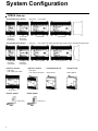
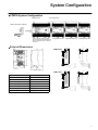
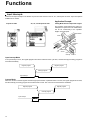
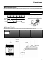
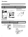
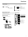
Contents
System Configuration . . . . . . . . . . . . . . . . . . . . . . . . . . . . . . . .
6
Specifications . . . . . . . . . . . . . . . . . . . . . . . . . . . . . . . . . . . . . . .
8
CPM1A Lineup . . . . . . . . . . . . . . . . . . . . . . . . . . . . . . . . . . . . . . . . . . . . . . . .
CPM1A System Configuration . . . . . . . . . . . . . . . . . . . . . . . . . . . . . . . . . . . .
External Dimensions . . . . . . . . . . . . . . . . . . . . . . . . . . . . . . . . . . . . . . . . . . . .
General Specifications . . . . . . . . . . . . . . . . . . . . . . . . . . . . . . . . . . . . . . . . . . .
Performance Specifications . . . . . . . . . . . . . . . . . . . . . . . . . . . . . . . . . . . . . . .
I/O Specifications . . . . . . . . . . . . . . . . . . . . . . . . . . . . . . . . . . . . . . . . . . . . . . .
Communications Adapter Specifications . . . . . . . . . . . . . . . . . . . . . . . . . . . .
6
7
7
8
9
10
13
Functions . . . . . . . . . . . . . . . . . . . . . . . . . . . . . . . . . . . . . . . . . .
14
Programming Instructions . . . . . . . . . . . . . . . . . . . . . . . . . . .
Peripheral Devices . . . . . . . . . . . . . . . . . . . . . . . . . . . . . . . . . .
Standard Models . . . . . . . . . . . . . . . . . . . . . . . . . . . . . . . . . . . .
20
24
25
Input Interrupts . . . . . . . . . . . . . . . . . . . . . . . . . . . . . . . . . . . . . . . . . . . . . . . . .
Quickresponse Inputs . . . . . . . . . . . . . . . . . . . . . . . . . . . . . . . . . . . . . . . . . . .
Highspeed Counter . . . . . . . . . . . . . . . . . . . . . . . . . . . . . . . . . . . . . . . . . . . . .
Interval Timer Interrupts . . . . . . . . . . . . . . . . . . . . . . . . . . . . . . . . . . . . . . . . .
Analog Setting . . . . . . . . . . . . . . . . . . . . . . . . . . . . . . . . . . . . . . . . . . . . . . . . . .
Pulse Output Function . . . . . . . . . . . . . . . . . . . . . . . . . . . . . . . . . . . . . . . . . . .
Communications . . . . . . . . . . . . . . . . . . . . . . . . . . . . . . . . . . . . . . . . . . . . . . . .
14
15
15
16
16
17
18
System Configuration
CPM1A Line-up
• DC input
CPU with AC Power Supply
10 I/O points
(Expansion
not possible)
30 I/O points
20 I/O points
(Expansion
not possible)
CPU with DC Power Supply
20 I/O points
(Expansion
not possible)
10 I/O points
(Expansion
not possible)
• RY output
• DC input
40 I/O points
• RY output / TR output (Only DC power supply can be used with TR-output type.)
30 I/O points
40 I/O points
Expansion I/O Unit
Expansion I/O Unit
CompoBus/S I/O Unit
Analog I/O Unit
• DC input
• RY output / TR output
• DC input
• RY output / TR output
CPM1A-SRT21
CPM1A-MAD01
20 I/O points
RS-232C Adapter
CPM1-CIF01
6
RS-422 Adapter
CPM1-CIF11
System Configuration
CPM1A System Configuration
Peripheral port
Connecting cable
CPM1-CIF01/CIF11 Adapter
Both AC and DC power supplies.
30-point CPU and 40-point CPU only.
May be expanded up to a maximum
of 3 Units.
Expansion I/O Unit
Expansion I/O Unit
Expansion I/O Unit
External Dimensions
CPM1-CIF01
30
21
56
50
30
21
61
50
90
90
81
50
W
DC power supply
85
AC power supply
Unit: mm
CPM1-CIF11
Model
W (mm)
CPM1A-10CDj-A/D
66
CPM1A-20CDj-A/D
86
CPM1A-30CDj-A/D
130
CPM1A-40CDj-A/D
150
CPM1A-20EDj
86 (depth: 50 mm)
CPM1A-8Ej/SRT21
66 (depth: 50 mm)
CPM1A-MAD01
66 (depth: 50 mm)
90
81
7
Specifications
General Specifications
Item
Power supply
y voltage/
g
AC power supply
f
frequency
DC power supply
Operating
g voltage
g
AC power supply
range
DC power supply
Power consumption
AC power supply
DC power supply
Inrush current
External power supply Power supply
((AC only)
y)
voltage
Power supply
output capacity
10-point I/O
20-point I/O
100 to 240 VAC, 50/60 Hz
24 VDC
85 to 264 VAC
20.4 to 26.4 VDC
30 VAC max.
6 W max.
30 A max.
30-point I/O
40-point I/O
60 VAC max.
20 W max.
60 A max.
24 VDC
200 mA
300 mA
Insulation resistance
20 MΩ min. at 500 VDC between the AC terminals and the protective earth
terminal.
Dielectric strength
2,300 VAC at 50/60 Hz for one minute with a leakage current of 10 mA max.
between all the external AC terminals and the protective earth terminal.
Noise resistance
1,500 V (peak to peak) with a pulse width of 0.1 to 1 µs, and 1-ns rise time
pulse (tested with a noise simulator)
Vibration resistance
10 to 57 Hz with an amplitude of 0.075 mm, and 57 to 150 Hz with an acceleration of 9.8 m/s2 in the X, Y, and Z directions for 80 minutes each (i.e. swept for
8 minutes, 10 times).
Shock resistance
147 m/s2 in the X, Y and Z directions 3 times each.
Ambient temperature (operating)
0° to 55°C
Ambient humidity (operating)
10% to 90% (no condensation)
Ambient environment (operating)
With no corrosive gas
Ambient temperature (storage)
–20° to 75°C
Terminal screw size
M3
Power supply holding time
10 ms min. for AC models, and 2 ms min. for DC models
Weight
AC model:
400 g max.
DC model:
300 g max.
AC model:
500 g max.
DC model:
400 g max.
AC model:
600 g max.
DC model:
500 g max.
AC model:
700 g max.
DC model:
600 g max.
Note: 1. The specifications of the Expansion I/O Unit are the same as for the CPU except that the power is supplied from the CPU
and the weight is 300 g.
2. TR output is only available to CPUs with DC power supply.
8
Specifications
Performance Specifications
Item
10-point I/O
20-point I/O
30-point I/O
40-point I/O
Control method
Stored program method
I/O control method
Combination of the cyclic scan and immediate refresh processing methods.
Programming language
Ladder diagram
Instruction word
Types
y
of
Basic instructions
i
instructions
i
Special
instructions
1 step per instruction, 1 to 5 words per instruction
Instruction
execution
i time
i
0.72 to 16.2 µs
MOV instruction = 16.3 µs
Basic instructions
Special
instructions
Program capacity
Maximum I/O
CPU only
points
With Expansion
I/O Unit
14 types
79 types, 139 instructions
2,048 words
10 points (6 input/
4 output points)
20 points (12 input/
8 output points)
30 points (18 input/
12 output points)
40 points (24 input/
16 output points)
---
---
90 points (54 input/
36 output points)
100 points (60 input/
40 output points)
Input bits
00000 to 00915 (Words 0 to 9)
Output bits
01000 to 01915 (Words 10 to 19)
Work bits (IR Area)
512: IR 20000 to IR 23115 (IR 200 to IR 231)
Special bits (SR Area)
384: SR 23200 to SR 25515 (SR 232 to SR 255)
Temporary bits (TR Area)
8: TR 0 to TR 7
Holding bits (HR Area)
320: HR 0000 to HR 1915 (HR 00 to HR 19)
Auxiliary bits (AR Area)
256: AR 0000 to AR 1515 (AR 00 to AR 15)
Link bits (LR Area)
256: LR 0000 to LR 1515 (LR 00 to LR 15)
Timers/Counters
Data memory
y
Read/Write
Read only
Interrupt processing:
External interrupt
128: TIM/CNT 000 to 127
100-ms timer: TIM 000 to TIM 127
10-ms timer: TIM 000 to TIM 127
Decremental counter, reversible counter
1,024 words (DM 0000 to DM 1023)
512 words (DM 6144 to DM 6655)
2 points (Response 4 points (Response time of 0.3 ms max.)
time of 0.3 ms max.)
Memory protection
Maintains the contents of the HR, AR, Counter and Data Memory Areas.
Memory backup
Flash memory:
Self-diagnostic function
User program, data memory (Read only) (Non-battery powered storage)
Super capacitor: Data memory (Read/Write), holding bits, auxiliary memory bits, counter (20-day storage at an ambient temperature of 25°C)
CPU error (watchdog timer), memory errors, I/O bus errors
Program check
No END instruction programming errors (constantly checked during operation)
Pulse output
1 point: 2 kHz
High-speed counter
1 point: Single phase at 5 kHz or two-phase at 2.5 kHz (linear counting method)
Incremental mode: 0 to 65535 (16-bit)
Decremental mode:–32767 to 32767 (16-bit)
1 point: Single phase at 5 kHz or two-phase at 2.5 kHz (linear counting method)
Incremental mode: 0 to 65535 (16-bit)
Decremental mode:–32767 to 32767 (16-bit)
Quick-response inputs
Together with the external interrupt input (minimum pulse width of 0.2 ms)
Input time constant
Can be set at 1 ms, 2 ms, 4 ms, 8 ms, 16 ms, 32 ms, 64 ms, or 128 ms.
Analog settings
2 points: (0 to 200)
Note: Bits that are not used for the I/O bits can be used as work bits.
9
Specifications
I/O Specifications
Input Circuit
CPU
Item
Specifications
Input voltage
Input impedance
24 VDC +10%/–15%
IN0000 to IN0002: 2 kΩ
Others: 4.7 kΩ
Input current (typical)
IN0000 to IN0002: 12 mA
Others: 5 mA
ON voltage
OFF voltage
ON delay (see note 1)
OFF delay (see note 1)
14.4 VDC min.
5.0 VDC max.
1 to 128 ms max.
(default: 8 ms) (see note 1)
1 to 128 ms max.
(default: 8 ms) (see note 1)
Circuit
Input
LED
4.7 kΩ
IN
Internal
Circuits
4.7 kΩ
COM
Note The polarity
y of the input power supply
y can be either
positive
iti or negative.
ti
Note: 1. The actual ON/OFF delay includes an input constant of 1, 2, 4, 8, 16, 32, 64, or 128 ms (default: 8 ms).
2. The delays for IN0000 to IN0002 are as follows when used for the high-speed counter.
Input
IN0000 (A-phase)
IN0001 (B-phase)
IN0002 (Z-phase)
Increment mode
Differential phase mode
2.5 kHz
5 kHz
Normal input
ON: 100 µs max. OFF: 500 µs max.
3. The delays for IN0003 to IN0006 are as follows when used for the high-speed counter.
Delay
0.3 ms max. (From the time of input ON until the interrupt subroutine is executed.)
Expansion I/O Unit
Item
Specifications
Circuit
+10%/
–15%
Input voltage
Input impedance
Input current (typical)
ON voltage
OFF voltage
ON delay
24 VDC,
4.7 kΩ
5 mA
14.4 VDC min.
5.0 VDC max.
1 to 128 ms max.
(default: 8 ms) (see note)
OFF delay
1 to 128 ms max.
(default: 8 ms) (see note)
Input
LED
4.7 kΩ
IN
COM
4.7 kΩ
Internal
Circuits
Note The polarity of the input power supply can be either
positive or negative.
Note: The actual ON/OFF delay includes an input constant of 1, 2, 4, 8, 16, 32, 64, or 128 ms (default: 8 ms).
10
Specifications
Output Circuit
CPU and Expansion I/O Unit
Relay Output
Specifications
Item
Maximum switching capacity
250 VAC/2 A (cos φ =1)
24 VDC/2 A
(4 A/common)
Minimum switching capacity
Relay
Electrical Resisservice
tance
life
load
5 VDC, 10 mA
300,000 times
OUT
Output
LED
Internal
Circuits
OUT
COM
Inductive
load
Mechanical
ON delay
OFF delay
Circuit
100,000 times
Maximum
250 VAC: 2 A
24 VDC: 2 A
10 million times
15 ms max.
15 ms max.
Transistor Output (Sink Type/Source Type) (CPU/Expansion I/O Unit)
Item
Specifications
Maximum switching capacity
+10%/
–15%,
24 VDC
(see note 1)
Leakage current
0.1 mA max.
Residual voltage
1.5 V max.
Circuit
300 mA
Sink Type
Output LED
Internal
Circuits
OUT
OUT
24 VDC
COM ((–))
Source Type
Output LED
ON delay
0.1 ms max.
COM (+)
Internal
Circuits
OFF delay
OUT
24 VDC
1 ms max. (see note 2)
OUT
Note: 1. The maximum switching capacity of the CPM1A with transistor outputs (sink type and source type) are limited to the currents shown in the following table for the common and for the Unit.
Item
Max. switching
capacity
10CDT/
10CDT1-D
0.9 A/Unit
20CDT-D/
20CDT1-D
0.9 A/common
1.8 A/Unit
30CDT-D/
30CDT1-D
0.9 A/common
2.7 A/Unit
40CDT-D/
40CDT1-D
0.9 A/common
3.6 A/Unit
20EDT/
20EDT1
CPM1A-8ET/
8ET1
0.9 A/common
1.8 A/Unit
2. When using the pulse output function of the CPM1A with transistor outputs (sink type and source type):
The output current must be within a range from 100 to 200 mA when using the output 01000 or 01001 as a pulse output with
the maximum frequency of 2 kHz. The outputs 01000 and 01001 will vary depending on the output current.
Load current
OFF delay
100 to 200 mA
0.2 ms max.
0 to 300 mA except for the above range
0.5 ms max.
11
Specifications
Analog I/O Unit
Item
Analog
g
i
inputs
Analog
g
output
(See
note 1.)
Voltage I/O
Number of inputs
Input signal range
Maximum rated input
External input impedance
Resolution
Overall precision
Converted A/D data
Number of outputs
Output signal range
External output max. current
External output allowed load
resistance
2
0 to 10 V or 1 to 5 V
±15 V
1 MΩ min.
1/256
1.0% of full scale
8-bit binary
1
0 to 10 V or –10 to 10 V
5 mA
---
Current I/O
4 to 20 mA
±30 mA
250 Ω rated
4 to 20 mA
--350 Ω
Resolution
Overall precision
Data setting
Conversion time (See note 2.)
1/256 (1/512 when the output signal range is –10 to 10 V.)
1.0% of full scale
8-bit binary with sign bit
10 ms/Unit max.
Isolation method
Photocoupler isolation between I/O terminals and PC
(There is no isolation between the analog I/O signals.)
Note 1. The voltage output and current output can be used at the same time, but the total output current cannot exceed 21 mA.
2. The conversion time is the total time for 2 analog inputs and 1 analog output.
CompoBus/S I/O Link Unit
Specifications
Item
Specification
Model number
CPM1A-SRT21
Master/Slave
CompoBus/S Slave
Number of I/O bits
8 input bits, 8 output bits
Number of words occupied in
CPM1A I/O memory
1 input word, 1 output word
Node number setting
Set using the DIP switch.
(Allocated in the same way as other Expansion Units)
Note: See the CompoBus/S Catalog (Q103) for more details on CompoBus/S communications.
12
Specifications
Communications Adapter Specifications
RS-232C Adapter and RS-422 Adapter
Specifications
Item
CPM1-CIF01
Level conversion between the CMOS level (CPU
side) and the RS-232C (peripheral device side)
CPM1-CIF11
Level conversion between the CMOS level (CPU
side) and the RS-422 (peripheral device side)
Insulation
The RS-232C (peripheral device side) is
insulated by a DC/DC converter and
photocoupler.
The RS-422 (peripheral device side) is insulated
by a DC/DC converter and photocoupler.
Power supply
Power is supplied by the CPU.
Power consumption
0.3 A max.
Transmission speed
38.4 Kbits/s max.
Vibration resistance
10 to 57 Hz with an amplitude of 0.075 mm, and 57 to 150 Hz with an acceleration of 9.8 m/s2 in the
X, Y and Z directions for 80 minutes each in accordance (i.e. swept for 8 minutes, 10 times).
Shock resistance
147 m/s2 in the X, Y and Z directions 3 times each.
Ambient temperature
(operating)
0° to 55°C
Ambient humidity
(operating)
10% to 90% (with no condensation)
Ambient environment
(operating)
With no corrosive gas
Ambient temperature
(storage)
–20° to 75°C
Weight
200 g max.
Functions
Memory Backup
The user program and memory area data in the CPU Unit are backed up by either one of the following methods.
The capacitor provides backup for a power interruption lasting
20 days at room temperature. If the power is expected to remain
OFF for a period exceeding this data backup period, consideration must be given to the design of the system so that no problems will occur when the set values become undefined ones. For
further details, refer to CPM1A Operation Manual (W317).
Capacitor backup time (days)
• Flash Memory:
User program, read-only DM area (DM 6144 to DM 6599), and PC Setup area (DM 6600 to DM 6655).
• Internal Capacitor:
DM areas other than the above, HR area, AR area, and
Counter area.
20
10
7
1
25
40
80
Ambient temperature (_C)
13
Functions
Input Interrupts
There are two input interrupts in the CPM1A 10-point I/O CPU and four in the 20-, 30-, and 40-point I/O CPUs. Input interrupts are
available in two modes.
Application Example:
10-point I/O CPU
20-, 30-, and 40-point I/O CPU
Cutting Metal Sheets to Specified Lengths
The proximity sensor detects the edge of a
metal plate to operate the cutter. Metal sheets
can be cut continuously to the specified
lengths at a high speed.
Metal sheets
Cutter
Conveyor
Proximity
sensor
Input
interrupt
Cutter
operation
signal
CPM1A
Input Interrupt Mode
If an input interrupt occurs, the regular program shuts down irrelevant of the cycle time, and the interrupt processing program is
executed immediately.
Regular program
Regular program
Interrupt program
Input interrupt
Counter Mode
When the number of external signals counted at high speed reaches a specified number of counts, the regular program shuts down,
and the interrupt processing program is executed at fixed counts. The count can be set between 0 and 65535.
Regular program
Regular program
Interrupt program
Input interrupt
Counter setting
14
Functions
Quick-response Inputs
There are two quick-response inputs for the CPM1A 10-point I/O CPU and four for the 20-, 30-, and 40-point I/O CPU (shared with the
interrupt inputs). Since an internal buffer is provided, the quick-response input function can even detect signals modified within one
cycle.
CPU
Input no.
10-point I/O CPU
20-point, 30-point, 40-point I/O CPU
Minimum input pulse width
0.2 ms
00003 to 00004
00003 to 00006
Application Example:
Overseeing
processes
Program
execution
I/O
refreshing
Overseeing Program
processes
execution
Calculating the Number of Chips
I/O
refreshing
The metal sensor counts the number of parts
that have passed. Steady counting can be
achieved even when the input-ON time is short.
0.2 ms min
Input signal
(00003)
CPM1A
IR 00003
One cycle
F2LP-WK4
F2LP-W
High-speed Counter
The CPM1A has a high-speed counter function that can be used in the incrementing and up/down mode. Using this function together
with the input interrupts enables zone comparison control or target value control irrelevant of the cycle time.
Incrementing mode
Item
Input no.
00000
00001
00002
Up/Down mode
Input method
Count input
--Reset input
Single-phase input
A-phase input
B-phase input
Z-phase input
Phase-difference, 4× inputs
Count frequency
5.0 kHz
2.5 kHz
Count range
0 to 65535
–32767 to 32767
Note: When using in the incrementing mode, the input 00001 can be used as an input contact.
Count input
00000
00001
00002
Reset input
Solenoid
Sensor
Rotary encoder
Inverter, etc.
15
Functions
Interval Timer Interrupts
The CPM1A has one interval timer. The interval timer shuts down the regular program irrelevant of the point in the cycle once the time
is up, and immediately executes an interrupt processing program. Interval timers are used in the following two modes.
One-shot mode
Item
Scheduled interrupt mode
Operation
An interrupt is executed only once when the time is up. Interrupts are executed repeatedly at fixed periods.
Setting time
0.5 ms to 319,968 ms (0.1-ms units)
Application Example:
Normal program
Computing the Sheet Speed
The number of pulse inputs is computed in the interrupt mode at a fixed time to calculate the speed.
Interval timer
MOV(21)
ADD(30)
CPM1A
Interrupt processing program
Encoder
SBN(92) 00
MOV(21)
RET(93)
END(01)
Analog Setting
The CPM1A contains two analog setting controls that can be used for a broad range of analog timer and counter settings. Turning the
setting control stores values of 0 to 200 (BCD data) in the SR area.
Analog setting
Analog setting 0
Analog setting 1
Analog setting 0
Analog setting 1
*Phillips screwdriver is required.
Storage area
Setting value (BCD)
0000 to 0200
SR 250
SR 251
Application Example:
Tact Operation Control of Conveyor Lines
A conveyor can be stopped temporarily as required for assembly
processes. When the timer function and limit switches are used in a
combination, conveyors can be stopped for a fixed time or can be run
at a constant speed for a fixed distance. Fine adjustment of the stopping time can be easily done by using the analog setting controls.
CPM1A
LS
Motor
16
Functions
Program Example
1.
Analog timer for 0.0 to 20.0 seconds
2.
A
Analog timer for 0.0 to 60.0 seconds
25313(ON)
TIM
000
250
BCD multiplication
MUL(32)
Value of the analog setting 0
(0 to 200)
Triples the above value
250
#0003
DM0500
Value of the analog
setting 0 (0 to 200)
Multiplication result (0 to 600)
B
TIM
001
DM 0500
Pulse Output Function
The CPM1A with transistor output has a function that is capable
of outputting a pulse of up to 2 kHz.
Program Example
1 scan turns ON.
When used in combination with a Stepping Driver or Servodriver, positioning can be easily performed.
25315
MOV(21)
#5000
DM 0000
Application Example
MOV(21)
#0002
DM 0001
Changing the speed of the Stepping Motor.
Sets the number of output pulses as
25,000 (times) in the data memory area.
DM 0001
0
0
0
DM 0000
2
5
0
MOV(21)
#0200
DM 0100
Sets the initial frequency to
2,000 pulses/second.
PULS(65)
000
000
DM 0000
Pulse rate setting
0
0
25315
Output point
01000 or 01001
1 scan turns ON.
00200
15000
Stepping Motor Driver
Speed change limit switch
00001
MOV(21)
#0020
DM 0100
Stepping Motor
ÉÉÉÉÉ
ÉÉÉÉÉ
ÉÉÉÉÉ
ÉÉÉÉÉ
ÉÉÉÉÉ
@SPED(64)
000
000
DM 0100
Pulse rate (BCD 8 digits)
Frequency conversion:
Output port (output point 01000)
Output mode (single)
Frequency data (x 10 Hz)
Changes to 200 Hz when the
limit switch is turned ON.
25,000 pulses
Output
1 kHZ
frequency
200 Hz
00000 turns ON
15000
Pulse rate
0001 turns ON (limit switch)
17
Functions
Communications
Host Link Communications
CPM1A host link communications consist of interactive procedures whereby the CPM1A returns a response to a command sent from
the IBM PC/AT or compatible computer. These communications allow the IBM PC/AT or compatible computer to read and write in the
CPM1A’s I/O Areas and Data Memory Areas as well as in areas containing the status of various settings.
Response
Command
1:1 Host Link Communications
RS-232C
Adapter
CPM1A
CPU
Response
Link Adapter
3G2A9-AL004-E
Command
1:n Host Link Communications
RS-422
Adapter
18
CPM1A
CPU
RS-422
Adapter
CPM1A
CPU
RS-422
Adapter
CPM1A
CPU
Functions
1:1 Links
With a 1:1 link, two CPM1As or a CPM1A and CQM1 or C200Hj are connected 1:1 with one side as the Master and the other as the
Slave to provide an I/O link of a maximum of 256 points (LR 0000 to LR 1515).
Example of a 1:1 Link between CPM1As
RS-232C Cable
RS-232C Adapter
RS-232C Adapter
CPM1A CPU
CPM1A CPU
Master
Slave
Link bits
Link bits
LR 00
WRITE
LR 00
WRITE area
READ area
LR 07
LR 08
LR 07
LR 08
READ area
READ
READ
WRITE area
LR 15
WRITE
LR 15
Limitations of the CPM1A 1:1 Link
CPM1A I/O links are limited to 16 words (LR 00 to LR 15). Therefore, use these 16 words (LR 00 to LR 15) on the CQM1 or C200Hj
side when forming 1:1 links with a CQM1 or C200Hj.
NT Links
High-speed communications can be achieved by providing a direct access through the use of the NT Link between the CPM1A and
Programmable Terminal.
Programmable Terminal
RS-232C
Adapter
RS-232C Cable
CPM1A CPU
19
Programming Instructions
Summary of Programming Instructions
Sequence Output Instructions
Function Code Chart
Table
symbols
f
Code
Details
Key operations for
specifying programming instructions
Allocated to instruction
keys on the Programming Console. These
need not be specified
with function codes.
Special instructions
specified with function
codes.
---
Code
FUN
WRITE
Differentiated Instructions
Differentiated instructions can sometimes be used for CPM1A
special instructions. Instructions marked with (@) in the mnemonics can also be used as differentiated instructions. Here the
input rise time (shift from OFF to ON) is used to execute the
instruction in just one cycle.
To specify an instruction, press the NOT Key after the function
code.
Example: Specifying the @MOV (21) instruction
FUN
2
1
NOT
WRITE
Instruction
Mnemonic
Code
OUTPUT
OUT
f
Outputs the result of logic to a
bit.
OUT NOT
OUT NOT
f
Reverses and outputs the result of logic to a bit.
SET
SET
f
Force sets (ON) a bit.
RESET
RSET
f
Force resets (OFF) a bit.
KEEP
KEEP
11
Maintains the status of the
designated bit.
DIFFERENTIATE
UP
DIFU
13
Turns ON a bit for one cycle
when the execution condition
goes from OFF to ON.
DIFFERENTIATE
DOWN
DIFD
14
Turns ON a bit for one cycle
when the execution condition
goes from ON to OFF.
Note: f: Instruction keys allocated to the Programming Console.
Sequence Control Instructions
Instruction
Mnemonic
Code
NO
OPERATION
NOP
00
---
END
END
01
Required at the end of the program.
INTERLOCK
IL
02
If the execution condition for
IL(02) is OFF, all outputs are
turned OFF and all timer PVs
reset between IL(02) and the
next ILC(03).
INTERLOCK
CLEAR
ILC
03
ILC(03) indicates the end of an
interlock (beginning at IL(02)).
JUMP
JMP
04
If the execution condition for
JMP(04) is ON, all instructions
between JMP(04) and
JME(05) are treated as
NOP(00).
JUMP END
JME
05
JME(05) indicates the end of a
jump (beginning at JMP(04)).
Sequence Instructions
Sequence Input Instructions
Function
Function
Function
Instruction
Mnemonic
Code
LOAD
LD
f
Connects an NO condition to
the left bus bar.
LOAD NOT
LD NOT
f
Connects an NC condition to
the left bus bar.
AND
AND
f
Connects an NO condition in
series with the previous condition.
AND NOT
AND NOT
f
Connects an NC condition in
series with the previous condition.
OR
OR
f
Connects an NO condition in
parallel with the previous
condition.
OR NOT
OR NOT
f
Connects an NC condition in
parallel with the previous
condition.
Instruction
Mnemonic
Code
TIMER
TIM
f
An ON-delay (decrementing)
timer.
COUNTER
CNT
f
A decrementing counter.
REVERSIBLE
COUNTER
CNTR
12
Increases or decreases PV by
one.
HIGHSPEED
TIMER
TIMH
15
A high-speed, ON-delay
(decrementing) timer.
AND LOAD
AND LD
f
Connects two instruction
blocks in series.
OR LOAD
OR LD
f
Connects two instruction
blocks in parallel.
Note: f: Instruction keys allocated to the Programming Console.
Timer/Counter Instructions
Function
Note: f: Instruction keys allocated to the Programming Console.
20
Programming Instructions
Step Instructions
Instruction
Mnemonic
Code
STEP DEFINE
STEP
08
STEP
START
SNXT
09
Data Conversion Instructions
Function
Defines the start of a new step
and resets the previous step
when used with a control bit.
Defines the end of step execution when used without a control bit.
Starts the execution of the
step when used with a control
bit.
Increment/Decrement Instructions
Instruction
Mnemonic
Code
INCREMENT
(@)INC
38
Increments the BCD content of
the specified word by 1.
DECREMENT
(@)DEC
39
Decrements the BCD content
of the specified word by 1.
Instruction
Mnemonic
Code
BCD TO
BINARY
(@)BIN
23
Converts 4-digit BCD data to
4-digit binary data.
BINARY
TO BCD
(@)BCD
24
Converts 4-digit binary data to
4-digit BCD data.
4 TO 16
DECODER
(@)MLPX
76
Takes the hexadecimal value
of the specified digit(s) in a
word and turns ON the corresponding bit in a word(s).
16 TO 4
DECODER
(@)DMPX
77
Identifies the highest ON bit in
the specified word(s) and
moves the hexadecimal value(s) corresponding to its
location to the specified digit(s)
in a word.
ASCII
CODE
CONVERT
(@)ASC
86
Converts the designated digit(s) of a word into the equivalent 8-bit ASCII code.
Function
BCD/Binary Calculation Instructions
Instruction
Mnemonic
Code
Function
BCD ADD
(@)ADD
30
Adds the content of a word (or
a constant).
BCD SUBTRACT
(@)SUB
31
Subtracts the content of a
word (or constant) and CY
from the content of a word (or
constant).
BCD MULTIPLY
(@)MUL
32
Multiplies the contents of two
words (or constants).
BCD DIVIDE
(@)DIV
33
Divides the content of a word
(or constant) by the content of
a word (or constant).
BINARY
ADD
(@)ADB
50
Adds the contents of two
words (or constants) and CY.
BINARY
SUBTRACT
(@)SBB
51
Subtracts the content of a
word (or constant) and CY
from the content of a word (or
constant).
BINARY
MULTIPLY
(@)MLB
52
Multiplies the contents of two
words (or constants).
BINARY
DIVIDE
(@)DVB
53
Divides the content of a word
(or constant) by the content of
a word and obtains the result
and remainder.
DOUBLE
BCD ADD
(@)ADDL
54
Add the 8-digit BCD contents
of two pairs of words (or
constants) and CY.
DOUBLE
BCD SUBTRACT
(@)SUBL
55
Subtracts the 8-digit BCD contents of a pair of words (or
constants) and CY from the
8-digit BCD contents of a pair
of words (or constants).
DOUBLE
BCD MULTIPLY
(@)MULL
56
Multiplies the 8-digit BCD contents of two pairs of words (or
constants).
DOUBLE
BCD DIVIDE
(@)DIVL
57
Divides the 8-digit BCD contents of a pair of words (or
constants) by the 8-digit BCD
contents of a pair of words (or
constants).
Function
Data Comparison Instructions
Instruction
Mnemonic
Code
COMPARE
CMP
20
Compares two four-digit hexadecimal values.
Function
DOUBLE
COMPARE
CMPL
60
Compares two eight-digit hexadecimal values.
BLOCK
COMPARE
(@)BCMP
68
Judges whether the value of a
word is within 16 ranges (defined by lower and upper limits).
TABLE
COMPARE
(@)TCMP
85
Compares the value of a word
to 16 consecutive words.
21
Programming Instructions
Data Movement Instructions
Shift Instructions
Instruction
Mnemonic
Code
MOVE
(@)MOV
21
Copies a constant or the content of a word to a word.
MOVE
NOT
(@)MVN
22
Copies the complement of a
constant or the content of a
word to a word.
Mnemonic
Code
Function
SFT
f/10
Copies the specified bit (0 or
1) into the rightmost bit of a
shift register and shifts the other bits one bit to the left.
WORD
SHIFT
(@)WSFT
16
Creates a multiple-word shift
register that shifts data to the
left in one-word units.
ASYNCHRONOUS
SHIFT
REGISTER
(@)ASFT
17
Creates a shift register that exchanges the contents of adjacent words when one is zero
and the other is not.
ARITHMETIC
SHIFT
LEFT
(@)ASL
25
Shifts a 0 into bit 00 of the
specified word and shifts the
other bits one bit to the left.
(@)XFER
BLOCK
SET
(@)BSET
71
Copies the content of a word
to a block of consecutive
words.
DATA EXCHANGE
(@)XCHG
73
Exchanges the content of two
words.
SINGLE
WORD
DISTRIBUTE
(@)DIST
80
Copies the content of a word
to a word (whose address is
determined by adding an offset
to a word address).
ARITHMETIC
SHIFT
RIGHT
(@)ASR
26
Shifts a 0 into bit 15 of the
specified word and shifts the
other bits one bit to the right.
DATA COLLECT
(@)COLL
81
Copies the content of a word
(whose address is determined
by adding an offset to a word
address) to a word.
ROTATE
LEFT
(@)ROL
27
MOVE BIT
(@)MOVB
82
Copies the specified bit from
one word to the specified bit of
a word.
Moves the content of CY into
bit 00 of the specified word,
shifts the other bits one bit to
the left, and moves bit 15 to
CY.
ROTATE
RIGHT
(@)ROR
28
Moves the content of CY into
bit 15 of the specified word,
shifts the other bits one bit to
the right, and moves bit 00 to
CY.
ONE DIGIT
SHIFT
LEFT
(@)SLD
74
Shifts a 0 into the rightmost
digit (4-bit unit) of the shift register and shifts the other digits
one digit to the left.
ONE DIGIT
SHIFT
RIGHT
(@)SRD
75
Shifts a 0 into the leftmost digit
(4-bit unit) of the shift register
and shifts the other digits one
digit to the right.
REVERSIBLE
SHIFT
REGISTER
(@)SFTR
84
Creates a single or multipleword shift register that can
shift data to the left or right.
(@)MOVD
83
Copies the content of a block
of up to 1,000 consecutive
words to a block of consecutive words.
Instruction
SHIFT
REGISTER
BLOCK
TRANSFER
MOVE
DIGIT
70
Function
Copies the specified digits
(4-bit units) from a word to the
specified digits of a word.
Logic Instructions
Instruction
Mnemonic
Code
COMPLEMENT
(@)COM
29
Turns OFF all ON bits and
turns ON all OFF bits in the
specified word.
LOGICAL
AND
(@)ANDW
34
Logically ANDs the corresponding bits of two words (or
constants).
LOGICAL
OR
(@)ORW
35
Logically ORs the corresponding bits of two words (or
constants).
EXCLUSIVE OR
(@)XORW
36
Exclusively ORs the corresponding bits of two words (or
constants).
EXCLUSIVE NOR
(@)XNRW
37
Exclusively NORs the corresponding bits of two words (or
constants).
22
Function
Note: f: Instruction keys allocated to the Programming Console.
Special Calculation Instruction
Instruction
Mnemonic
Code
BIT
COUNTER
(@)BCNT
67
Function
Counts the total number of bits
that are ON in the specified
block of words.
Programming Instructions
Pulse Output Control Instructions
Subroutine Instructions
Instruction
Mnemonic
Code
Function
SUBROUTINE ENTER
(@)SBS
91
Executes a subroutine in the
main program.
SUBROUTINE
ENTRY
SBN
92
Marks the beginning of a subroutine program.
SUBROUTINE RETURN
RET
93
Marks the end of a subroutine
program.
MACRO
MCRO
99
Calls and executes the specified subroutine, substituting
the specified input and output
words for the input and output
words in the subroutine.
Interrupt Control Instructions
Instruction
Mnemonic
Code
INTERVAL
TIMER
(@)STIM
69
Controls interval timers used
to perform scheduled interrupts.
Function
INTERRUPT
CONTROL
(@)INT
89
Performs interrupt control,
such as masking and unmasking the interrupt bits for I/O interrupts.
Peripheral Device Control Instructions
I/O Unit Instructions
Instruction
Mnemonic
Code
7-SEGMENT DECODER
(@)SDEC
78
Converts the designated digit(s) of a word into an 8-bit,
7-segment display code.
I/O REFRESH
(@)IORF
97
Refreshes the specified I/O
word.
Instruction
Mnemonic
Code
Function
SPEED
OUTPUT
(@)SPED
64
Outputs pulses at the specified
frequency. The output frequency can be changed while
the pulses are being output.
SET
PULSES
(@)PULS
65
Outputs the specified number
of pulses at the specified frequency. The pulse output cannot be stopped until the specified number of pulses have
been output.
Damage Diagnosis Instructions
Instruction
Mnemonic
Code
Function
FAILURE
ALARM
(@)FAL
06
Generates a non-fatal error
when executed. The Error/
Alarm indicator flashes and the
CPU continues operating.
SEVERE
FAILURE
ALARM
FALS
07
Generates a fatal error when
executed. The Error/Alarm indicator lights and the CPU
stops operating.
Special System Instructions
Instruction
Mnemonic
Code
SET
CARRY
(@)STC
40
Sets Carry Flag 25504 to 1.
Function
CLEAR
CARRY
(@)CLC
41
Sets Carry Flag 25504 to 0.
Function
Display Instruction
Instruction
Mnemonic
Code
MESSAGE
(@)MSG
46
Function
Reads up to 8 words of ASCII
code (16 characters) from
memory and displays the message on the Programming
Console or other Peripheral
Device.
High-speed Counter Control Instructions
Instruction
Mnemonic
Code
MODE
CONTROL
(@)INI
61
Starts and stops counter operation, compares and
changes counter PVs, and
stops pulse output.
Function
PV READ
(@)PRV
62
Reads counter PVs and status
data.
COMPARE
TABLE
LOAD
(@)CTBL
63
Compares counter PVs and
generates a direct table or
starts operation.
23
Peripheral Devices
SYSMAC-CPT: WS01-CPTB1-E
(for Windows 3.1 or 95)
IBM PC/AT or compatible
CPM1A CPU
SYSMAC Support Software: C500-ZL3AT1-E
(for MS-DOS)
ÇÇÇÇ
ÇÇÇÇ
Peripheral Device Connecting Cable
CQM1-CIF02
Programming Console
Connecting Cable
Programming
Console
Programming Console
(With Connecting Cable)
ÇÇ
ÇÇ
C200H-CN222/CN422
(2 m/4 m)
C200H-PRO27-E
24
CQM1-PRO01-E
Standard Models
CPU
Name
10-point I/O
Power supply
Output method
AC power supply
DC power supply
y
Relay output
Relay output
Transistor output
(sink type)
Input
points
6 points
Output
points
4 points
Transistor output
(source type)
20-point I/O
AC power supply
DC power supply
y
Relay output
Relay output
Transistor output
(sink type)
AC power supply
DC power supply
y
Relay output
Relay output
Transistor output
(sink type)
12 points
8 points
AC power supply
DC power supply
y
Relay output
Relay output
Transistor output
(sink type)
U,, C,, N,, L
U, C, CE
CPM1A-20CDR-A
CPM1A-20CDR-D
CPM1A-20CDT-D
U,, C,, N,, L
U, C, CE
CPM1A-20CDT1-D
18 points
12 points
Transistor output
(source type)
40-point I/O
CPM1A-10CDR-A
CPM1A-10CDR-D
CPM1A-10CDT-D
Standards
CPM1A-10CDT1-D
Transistor output
(source type)
30-point I/O
Model
CPM1A-30CDR-A
CPM1A-30CDR-D
CPM1A-30CDT-D
U,, C,, N,, L
U, C, CE
CPM1A-30CDT1-D
24 points
16 points
Transistor output
(source type)
CPM1A-40CDR-A
CPM1A-40CDR-D
CPM1A-40CDT-D
U,, C,, N,, L
U, C, CE
CPM1A-40CDT1-D
Expansion I/O Unit
Expansion
Unit
Max.
number
of Units
Expansion I/O 3 Units
U i
Units
max.
(See
note.)
Analog I/O
Unit
CompoBus/S
I/O Link Unit
3 Units
max.
(See
note.)
3 Units
max.
(See
note.)
Output type
Inputs
Outputs
Model
Standards
Relay
Transistor (sinking)
Transistor (sourcing)
---
12
8
8
---
CPM1A-20EDR1 U, C, CE
CPM1A-20EDT
U, C, CE
CPM1A-20EDT1 U, C, CE
U, C, CE
CPM1A-8ED
Relay
---
8
CPM1A-8ER
U, C, CE
Transistor (sinking)
Transistor (sourcing)
Analog
---
8
CPM1A-8ET
CPM1A-8ET1
U,, C,, CE
2
1
U, C, CE
CPM1A-MAD01
---
I/O Link of 8 input bits
and 8 output bits
U, C, CE
CPM1A-SRT21
Note: Only one Expansion Unit can be connected if an NT-AL001 Adapter is connected to the CPU Unit’s RS-232C port.
• U: UL, C: CSA, N: NK, L: Lloyd, CE: EC Directives
Please contact OMRON representative for application conditions.
25
Standard Models
RS-232C Adapter, RS-422 Adapter, Connecting Cable, Link Adapter
Name
Function
Converts peripheral port levels.
RS-232C Adapter
RS-422 Adapter
Model
Standards
U, C, N, L,
CE
CPM1-CIF01
CPM1-CIF11
Connecting Cable
3.3-m cable used to connect IBM PC/AT
or compatible personal computers.
CQM1-CIF02
U, C, N, L,
CE
Link Adapter
Converts RS-232C and RS-422 levels.
3G2A9-AL004-E
---
Programming Console
Name
Programming
g
g Console
Model
Standards
With a 2-m cable
--2-m Connecting Cable for
C200H-PRO27-E
Function
CQM1-PRO01-E
C200H-PRO27-E
C200H-CN222
U, C, N, CE
U, C, CE
---
4-m Connecting Cable for
C200H-PRO27-E
C200H-CN422
---
Programming Software
Name
Operating system
Operating environment
Model
SYSMAC-CPT
Windows 3.1 or 95
Used in IBM PC/AT or compatible personal computers
(i486DX/Pentium)
WS01-CPTB1-E
SYSMAC Support Software
MS-DOS Ver. 5.0 or later
Used in IBM PC/AT or compatible personal computers
(i386/i486/Pentium)
C500-ZL3AT1-E
26
• U: UL, C: CSA, N: NK, L: Lloyd, CE: EC Directives
Please contact OMRON representative for application conditions.
OMRON Corporation
Systems Components Division
66 Matsumoto
Mishima-city, Shizuoka 411-8511
Japan
Tel: (81)559-77-9633/Fax: (81)559-77-9097
Regional Headquarters
OMRON EUROPE B.V.
Wegalaan 67-69, NL-2132 JD Hoofddorp
The Netherlands
Tel: (31)2356-81-300/Fax: (31)2356-81-388
OMRON ELECTRONICS, INC.
1 East Commerce Drive, Schaumburg, IL 60173
U.S.A.
Tel: (1)847-843-7900/Fax: (1)847-843-8568
OMRON ASIA PACIFIC PTE. LTD.
83 Clemenceau Avenue,
#11-01, UE Square,
Singapore 239920
Tel: (65)835-3011/Fax: (65)835-2711
Authorized Distributor:
Cat. No. P039-E1-4
Note: Specifications subject to change without notice.
Printed in Japan
0699-3.5M