1
43-200 Pszczyna, ul. Staromiejska 31b
tel. 032 326 30 70, fax 032 447 73 30
www.gorke.com.pl, e-mail: [email protected]
USER’S MANUAL AND SPECIFICATION
type of the device: SBA-430 base station
433,92 MHz, hopping code KeeLoq
TECHNICAL PARAMETERS
Basic supply:
- voltage supply: 187V -253 V AC
- power consumption <1,2 A
Reserve supply:
- voltage: 12 V DC
- accumulator: internal 12V/7Ah or external 17-34Ah
- power consumption: 0,5A in the reception mode
Radio channel:
- type of receiver: superheterodyne
- type of modulation: FFSK
- operating frequency: 433,92 MHz
- sensitivity: <-115 dBm
dimensions: 3U cage of the 19" system
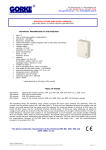
The mechanical construction of the base station is based on the 3U cage of the 19” (RACK) system. It is made of
aluminium profiles and is designed to be stored in standard wardrobes (RACK), to be inbuilt into a control desk
or as a free-standing device.
The basic version comprises:
block of the microprocessor controller with a LCD graphic display (illuminated, mono FSTN 320x240)
and a touchscreen
input controller module
impulse feeder
computer keyboard
internal accumulator 12V/7Ah (option)
WLC 201 amplifier module
On the
-
back panel of the cage you can find:
supply junction 230V/AX with a cut-out and a fuse
the internal receiver (WLC 201) junction
computer keyboard junction (PS2 type)
RS 232 (DB 9) junction – communication with a computer and an application for alarm monitoring
station
RS 232 (DB 9) junction – serial printer
junctions: RS 232 / RS 485 which are installed and configured according to needs
connecting cables for the outer accumulator 12V/17-34Ah
This solution keeps the functionality comparable with the extended monitoring systems but simultaneously it
takes into consideration particular requirements for operating on separate objects and areas. Operating on the
433 MHz frequency (a bandwidth which does not require permissions) facilitates the work. It allows for building
a system adjusted to present requirements in short time and its further extension when necessary. The
transmission based on the hopping code algorithms (KeeLoq by Microchip Technology) guarantees high
resistance to interferences and attempts to exchange the signals. Simultaneously it allows for using a wide
variety of produced devices.
The examples of use are a good presentation of the abilities of the VIRGO-430 system:
monitoring the alarm systems which are installed in flats on a separate housing estate with its own local
security stand
market hall with many stands (the employees were equipped with panic remote controls)
guarded car park with registered enters and leavings on the basis of turning the remote control on
which controls the barrier’s work
monitoring objects on the area of allotment gardens
panic and calling buttons installed in supermarket’s cash desks
monitoring object on the area of a business entity which has institutional security service (several or
several dozen objects, the operating area: several kilometres)
Gorke Electronic
USER’S MANUAL AND SPECIFICATION: type of the device: SBA-430 base station
page: 1
Thanks to the advanced abilities of the base station, it is possible to combine the presented uses, keeping the
simplified service on the operator’s party even when using 1000 senders and remote controls. The operating
area can start from several hundred metres but it can also be expanded with use of retransmitters to even
several kilometres. The wide variety of devices in our offer allows for the adequate choice of configuration,
taking into consideration the technical parameters and economic requirements.
The SBA-430 BASE STATION – the radio signals reaching the station are received by the WLC-201 amplifier and
then they are transmitted to the main module of the station. The events codes which are received from the
senders and remote controls later are transformed into text information and in such form they are available for
the operator on the LCD display. Linking the codes with descriptions is performed according to the conversion
table prepared by the station’s administrator. Some of the codes can be set as auto-logging (for example, tests)
and then they will appear only in the auxiliary window and simultaneously, they will not require being serviced
by the operator. All other events are displayed in the main window together with information about reception
time, event code and object’s number. Such events turn the internal acoustic signalling device on and they
remain on the screen until the operator confirms their acceptance. The time of event service is registered in the
events buffer. Pressing the space button on the keyboard displays descriptive information connected with the
serviced object and event.
The range of information which can be saved in the station and displayed after receiving a signal from a given
object comprises: number of object, name, address, 3 x phone number, password, test period, area, service
person, status, and description field. The station’s memory allows for entering information about 1000 objects.
For each object an independent supervision over the time period between the received signals can be run. When
the period is exceeded, the code of no connection is generated. In the examination either only test signals or all
the signals from a given object may be taken into consideration.
If you connect a printer to the station, you will get a updated register of the received signals with the description
of the event code and name of the object. The station has an in-built calendar and a real time clock with an
independent battery supply. The internal buffer has the capacity of 4000 events. It can be viewed or printed with
appropriate sorting – according to time, event code or object’s number. It is also possible to copy the content of
the events buffer to an external computer through the RS 232 junction.
Furthermore, the station can operate in connection with an additional computer, which has an application for
monitoring station.
1.
Description of monitoring station ports
COM1 (female) – connector which activates the process of software updating; for normal operating is a place of
connecting the WLC receiver
COM2 (male) – signal output (PC – format SIMS, VIRGO)
COM3 (male) – output for serial printer
COM4 (male) – PC input for updating the “CENT” module software
COM5 (male) – signal intput (VIRGO format)
COM6 (male) - signal output (VIRGO format)/ PC input for updating the “QEEL” module software
COM7 (male) – PC input for additional functions (sending the content of the memory buffer)
2.
Connecting devices in the normal operating mode
COM1 – WLC 201 receiver
COM2 – NULL MODEM connected through a cable with a computer with the monitoring station software (SIMS,
KRONOS etc.). It can be left free for the autonomic operating of the monitoring station
COM3 – connected to a serial printer with a cable according to printer’s specification
COM4 – free (NC)
COM5 – NULL MODEM connected through a cable with COM6 of the station (included)
COM6 – NULL MODEM connected through a cable with COM5 of the station (included)
COM7 – free (NC)
3.
Serial printer settings
-
serial port speed: 9600
data bits: 8
stop bits: 1
evenness (parzystość): none
The SBA-430 station has the ability of exchanging the software (for example, when a producer introduces new
functions facilitating operator’s work). This process does not require sending the device to the producer – a user
can perform the process himself, using a computer. The necessary software may be obtained directly in the
GORKE Electronic company or on the website www.alarmsoft.com.pl. The version of the software which is
installed on the station can be checked after turning the station on (the information about the version and the
compilation date is displayed on the screen).
Gorke Electronic
USER’S MANUAL AND SPECIFICATION: type of the device: SBA-430 base station
page: 2
4.
Devices’ connection in the mode of updating the “CENT” module software
COM1 – connect a plug which activates the updating function (the plug is included, the switch on the plug is set
in the position “CENT”)
COM4 – connect it with a NULL MODEM cable to a computer on which you will launch the application updating
the software (computer’s COM1)
Note: during the updating process, it does not matter what is connected to the ports COM2 and COM3, COM5,
COM6, and COM7 – can be unplugged or remain in the configuration for the normal operating
5.
Steps of updating the “CENT” module
1)
turn the monitoring station off (disconnect the power supply – put the “SUPPLY” switch on the back part
of the case into the “0” position and then the battery supply
2) plug the plug which activates the updating process in (the switch on the plug should be in the position
“CENT”)
3) disconnect the keyboard from the station
4) connect the COM4 of the station with the serial port (COM1) of the computer on which you will launch
the updating application
5) turn the power supply on (no matter of what source)
6) launch the application which reloads the station cent07xx.bat
7) you will see a messages on the screen: about correct opening the port, about the process progression
and at last, about finishing the process. In case of error during the reloading, check whether the plugs
were connected correctly (according to the above description) and check whether another program
using computer’s COM1 is not launched on the computer
8) after successful reloading the software, turn the power supply off
9) connect the station according to the configuration for the normal operating
10) connect the power supply and the battery
If there is a necessity to use the COM2 port of the computer in the process of updating the software, perform
the following procedure:
edit the cent07xx.bat file
in the second line change the value of the COM parameter from 1 to 2
save the change
run the updating process as described above
6.
Devices’ connection in the mode of updating the “QEEL” module software
COM1 – connect a plug which activates the updating function (the plug is included, the switch on the plug is set
in the position “QEEL”)
COM6 – connect it with a NULL MODEM cable to a computer on which you will launch the application updating
the software (computer’s COM1)
Note: during the updating process, it does not matter what is connected to the ports COM2, COM3, COM5, COM7
and COM4 – they can be unplugged or remain in the configuration for the normal operating
7.
1)
2)
3)
4)
5)
6)
7)
8)
9)
Steps of updating the “QEEL” module
turn the monitoring station off (disconnect the power supply – put the “SUPPLY” switch on the back part of
the case into the “0” position and then the battery supply
plug the plug which activates the updating process in (the switch on the plug should be in the position
“QEEL”)
connect the COM6 of the station with the serial port (COM1) of the computer on which you will launch the
updating application
turn the power supply on (no matter of what source)
launch the application which reloads the station QEELxx.bat
you will see a messages on the screen: about correct opening the port, about the process progression and
at last, about finishing the process. In case of error during the reloading, check whether the plugs were
connected correctly (according to the above description) and check whether another program using
computer’s COM1 is not launched on the computer
after successful reloading the software, turn the power supply off
connect the station according to the configuration for the normal operating
connect the power supply and the battery
If there is a necessity to use the COM2 port of the computer in the process of updating the software, perform
the following procedure:
edit the cent07xx.bat file
in the second line change the value of the COM parameter from 1 to 2
save the change
run the updating process as described above
Gorke Electronic
USER’S MANUAL AND SPECIFICATION: type of the device: SBA-430 base station
page: 3
8.
The event will be saved to the events history if:
When connected to the PC:
no recording to the buffer
1) when there is no connection with PC
if the buffer’s memory if overloaded (over 31 events)
the events remain unserviced – the date and hour of receptions is entered as the servicing time
3) when pressing “ENTER” (servicing the even from the operator’s buffer)
Last 4096 events are remembered in the events history.
Plug which updates the software exchange process:
for “QEEL” – pins 2-5 shorted
for “CENT” – pins 1-5 shorted
9.
WLC (COM1) socket outlet :
123456789-
activation of the software exchange for the “CENT” module
activation of the software exchange for the “QEEL” module
(+12V DC)
(+12V DC)
GND
WLC line
WLC line
SAB
SAB
10. Description of the base station’s functions and the keyboard control
“a” – exit (just as Esc)
“t” – set time
“r” – events history, scroll using the cursors ↑↓ - exit “a”
“space” – details of the object – exit “a”
“e” – edit object; set the type of definition on 1
“m” – move to the next page of unserviced events
“k” – move to the previous page of the unserviced events
“f” – format the MMC – database of clients, autolog entries, code descriptions, event memory will be deleted
“i” – auto log in – edit codes
“l” – events codes – edit descriptions
“g” – edit filters
“n” – learn a remote control
“q” – send the clients based through RS – not used
“y” – view the entered senders and part of the name
“x” – delete sender
“d” – print the events buffer – using the filter
“p” – set the code for the event: no test signal (common for all objects)
“s” – choose transmission protocol between the SBA-430 station and a computer
“Enter” – service the event (remove from the operator’s list)
11. The display of the base station consists of two parts:
1)
2)
larger area – operator’s screen – in the normal operating it displays event which are supposed
to be serviced
smaller area – it displays serial numbers of the three last received senders
When moving in the user’s menu, obey the following rules:
to enter a particular settings menu, press one of the letters describe above
you can exit the menu by reaching the end of settings or by pressing the “a” button
the “m” and “k” buttons allow for moving to the next/previous page in the menu
to move between the lines, use the ↑↓ cursors
-
Gorke Electronic
USER’S MANUAL AND SPECIFICATION: type of the device: SBA-430 base station
page: 4
PROGRAMMING SENDERS TO THE STATION’S MEMORY
The base station can cooperate with senders produced by GORKE Electronic, that is remote controls of the PUK
and RNB series, stationary senders PNH, NRP (except NRP 102K). Only after entering the sender to the station’s
memory, will it be noticed by the device.
Follow the procedure:
1. press the “n” button on the station’s keyboard
2. press the control’s button or release the sender to activate a transmission. On the smaller screen you
will see serial number of the sender – it means that the station received the given sender. Note: a serial
number of a control which has already been entered or serial numbers of controls not produced by
GORKE Electronic will not appear on the screen.
3. on the display you will see a question whether to save the number. Check whether on the lower screen
the last received number is the number of a new sender (the last received serial number is located in
the bottom of the screen). If yes, press “t”; if the number is different, press “n” – the station will quit
the mode of learning a new remote control.
4. on the display you will see a question about the number of object under which the sender is supposed to
be saved in the station’s memory (select a number between 0-999. NOTE: if you choose a number
under which another remote control was entered, the previous sender will be overwritten)
5. after this operation, release the sender again and activate a transmission. If the operations succeed and
the serial number is correctly entered, you will see on the main screen an event from a given sender. If
it is not displayed, repeat the learning process.
Each sender which was entered into the memory has its own number (0-999). You can check it by activating a
transmission – on the main operator’s screen you will see another entry which contains the hour of the signal
reception and next – the number under which the sender was entered, and last – an event code (if descriptions
are assigned to the event codes, instead of the code, you will see a description).
So you already know the sender’s number under which it was entered into the station’s memory. Not you can
create a short description for each sender. Follow the procedure:
1. press the “e” button – on the screen you will see a question about the sender’s number (give the
number which you obtained in the way described above – NOT THE SERIAL NUMBER – and confirm it by
pressing “enter”)
2. fill in the fields:
a) type of definition: 1
b) name: give the name which is supposed to be displayed on the operator’s screen and printed on the
serial printer when the signal from a given sender is received
c) street
d) house number
e) city
f) code
g) optional description
h) test period in minutes: ………………. It is a period if time in which a test signal is supposed to be received
from the sender. It if does not happen, an event will be generated (“no test”)
i) number of conversion table: 1 – no conversion. If you enter 2, a number “20” will be added to the codes
of events coming from this sender.
3.
After you fill all the fields, you will see a question: “save changes?” – confirm with the “t” button, cancel
with the “n” button.
The station remembers the 4000 last received signals. They can be viewed, printed, sent to computer and saved
on disk. The parameter connected with these function is so-called filter function. It enables selecting from the
memory such events which fulfil particular criteria:
event code
number of the sender
date of receiving the signal
You can set the filters with the “g” button.
To launch the menu of browsing the events selected by the filters, press the “r” button.
Press the “d” button to print the history of events selected by the filters.
Gorke Electronic
USER’S MANUAL AND SPECIFICATION: type of the device: SBA-430 base station
page: 5
FUNCTIONS AND OPERATING OF THE SBA-430 STATION
During the normal operating, the events from the senders received by the base station are displayed on the
main operator’s screen. You can display the information assigned to the sender (name, address, additional
description) by pressing the “space” button (but first, you have to select the event with the cursor).
You can service the event by selecting it with a cursor and pressing “enter”. In this moment, the event is
rewritten to the events memory as serviced.
There are two more cases then an event is rewritten to the events memory as serviced:
if on the operator’s screen 32 events are displayed, the next coming signals will be automatically
rewritten to the memory. The hour of receiving the event will be written down as the hour of servicing.
when a given even is set as “auto logging in”, that is, an event which does not require operator’s service
(for example, test signals). The codes of auto-logging events can be edited in the menu called with the
“j” button. The auto-logging events are not sent to the serial printer (COM3).
The event code may have the value between 00-FF. If no description is assigned to the event code, then on
operator’s screen and on the printer the code number of the event will be seen. Entering the descriptions of
codes facilitates the operator’s work, for example, instead of an event code “00”, a “test” can
displayed/printed; instead of “03” – “assault” etc. You can change these settings by choosing the menu with
“L” button.
the
the
be
the
The station enables also the functions of signal tests servicing. In the menu called with the “p” button you can
set a code of an event generated after the station states that there is no signal from a given sender for a period
longer than it is entered in the sender’s description (description menu is called with the “e” button – it is
described above).
It is intuitive to use a lot of options, for example, time setting (“t” button), formatting the MMC card (“f” button),
browsing the entered senders and parts of name (“y” button), deleting a sender (“x” button), etc.
The SBA-430 base station can cooperate with a computer on which an application of monitoring station is
installed. You can choose of the two protocols for the transmissions between the station and the computer:
– SIMS
– VIRGO.
The choice is confirmed with the “s” button.
An additional function of the SBA-430 station is controlling the relay output, which is outlet on the back part of
the case (option). The contract outlet on the outside can be shorted or unshorted after a signal comes from a
sender with appropriate code. Press “z” button to configure the relay output (type NO or NC) and to edit the
events codes. To quit the menu – press “a” button.
Gorke Electronic
USER’S MANUAL AND SPECIFICATION: type of the device: SBA-430 base station
page: 6