1
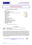
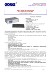
43-200 Pszczyna, ul. Staromiejska 31b
tel. 032 326 30 70, fax 032 447 73 30
www.gorke.com.pl, e-mail: [email protected]
USER’S MANUAL
type of the device: IDO 500 identifying receiver
TECHNICAL PARAMETERS
•
•
•
•
•
•
•
•
•
•
•
•
•
•
•
•
•
•
type of receiving module: superheterodyne
sensitivity: -115 dBm
frequency: 433,92 MHz
radio transmission: KeeLoq hopping code by Microchip
Technology
memory capacity: 500
supply: 12 V AC/DC or 24 V AC/DC
power consumption:
static: 40 mA for 12 V DC
maximal: 150 mA for V DC
capacity:
relay output NO: 10A/ 230 V DC
number of relays: 4
relay's operating mode: mono, bistable or temporary
time scope for the mono mode: ~1s-4min20s
level of security: IP 65
operating temperature range: -20 to +40 °C
antenna socket: BNC 50 Ohm
dimensions (mm): 130*130*35
cooperation: any GE sender
cable output: 3xPG 9 gland
operating range (m)*: 200-1000
* the range depends on the type of the sender
TABLE OF RANGE
200 metres
400 metres
600 metres
1000 metres
types of the remote controls: PUK 101, PUK 102, PUK 104, PUK 112-1, PUK 112-2
PNH 201 hermetic button
PUK 303 remote control
types of the remote controls: RNB 101, RNB 101S, and NRP 100 stationary sender
The above range concerns the open space (without any obstacles, when the receiver and the remote control
can “see each other”). If there are any obstacles between the receiver and the sender, one must assume that
the range would be reduced: for wood and plaster it would be 5-20% lower, for bricks 20-40% lower, and for
reinforced concrete 40-80% lower. If there are many obstacles we advise to configure the sets using the
receivers of the SH class, to use retransmitters or stronger remote controls. If there are metal obstacles,
using the radio systems is not recommended. In such situation, consider installing WLC 201 module, which
helps to avoid the problem.
The device meets the requirements of the directives EMC 89/ 336/ EEC
and RTTE 1999/ 5/ EC.
Gorke Electronic
User’s manual: receiver type IDO 500
page: 1
The receiver’s use - IDO 500 is used in various types of devices remote controlling, when the superior
parameter is either distinguishing the signal’s source or the large memory capacity (500). It is also often
chosen because of the possibility of deleting the senders individually from the receiver’s memory. In systems
containing a dozen or several dozen remote controls, using the relay receivers like RSU or OPC is very
uncomfortable in case of deleting one or several controls. The perfect solution in such situation is a receiver
with an option of individual deleting, like IDO 500.
The receiver’s operating - after being connected to the supply, the receiver launches test procedures. When
they are finished, on the display you will see a message READY. In the OPERATING mode the device receives
the radio signals and after receiving a right transmission it controls the relays according to the settings. On
the display a message will appear: KEY 3 PILOT 14, which means that key 3 was pressed on the remote
control saved in the receiver’s memory under the number 14. Simultaneously it generates a short sound
signal from the internal signalling device. The message on the display remains until the next right
transmission is received. If the relay receives a signal from a remote control which has not been entered into
the receiver’s memory, the message on the display will not change. Instead, a long sound signal is generated.
The switch should be set in the 12V or 24V position, depending on the value of the supply voltage. With the
potentiometer CONTRAST you can set the contrast of the display. The buttons of the remote controls were
assigned to the relays permanently: button 1 controls the relay number1, button 2 controls the relay number
2 etc. If you use a one–button remote control, you will be able to control only the relay number 1. Only a 4button remote control enables you to control all the relays.
The potentiometer CONTRAST is used to set the contrast on the LCD display.
The terminal strip SUPPLY is used to connect the power lead.
• NO C1 NC – output of the relay 1
• NO C2 NC - output of the relay 2
• NO C3 NC - output of the relay 3
• NO C4 NC - output of the relay 4
USER’S MANUAL
You can enter the programming mode by pressing the MENU button.
1. MAIN MENU
It consists of several options: LEARN, DELETE, OPERATING MODES, EDIT TIME, QUIT.
You can move in the main menu using the arrow up and arrow down buttons. For example, in order to enter
the DELETE option, you need to select DELETE on the display and press YES. If you want to exit the
programming mode and go to OPERATING mode, you need to choose QUIT in the main menu and press the
YES button. On leaving the programming menu, the device saves the current settings. They will be saved also
if there is lack of supply.
2. LEARN OPTION – it is used to enter the remote controls into the receiver’s memory
When you enter the LEARN option, on the display you will see FREE 0004 which means that the first free cell is
the cell number 4. After a few seconds, the message will change into PRESS THE CONTROL – the receiver is
waiting for the signal from the remote control, which is supposed to be entered into the receiver’s memory
under a number chosen before (4). Now press any button of the remote control being entered. The receiver
confirms the receipt of the signal with a long acoustic signal and after saving, it moves to the main menu. On
the display you can see the message LEARN. To enter the next pilot, press the YES button and follow the
above procedure.
The remote controls can be entered only to the subsequent cells. If, for example, 200 remote controls were
entered to the memory and the control number 130 had to be removed (for example, because it was lost),
then while entering the LEARN option first you have to save the control under the number 130 and only then,
under the number 201.
In case of entering the same remote control twice, the receiver does not report an error. For example, the
remote control was entered under the numbers 12 and 34 so, during the reception of signals from this control,
you will always see on the display the number of the earlier cell, here: 12. You should remove one of the
records (12 or 34).
If during entering a new control you wish to abort, press the MENU button shortly when the message PRESS
THE CONTROL is shown. It will cause moving to the main menu.
Gorke Electronic
User’s manual: receiver type IDO 500
page: 2
In order to avoid entering an accidental remote control into the receiver’s memory it is recommended to
disconnect the antenna for the time of learning.
3. DELETE OPTION – it is used to delete the remote controls from the receiver’s memory
After entering the DELETE option, on the display you will see a message REMOTE CONTROL 1. If you want to
delete the control which was saved in the cell number 23, set the required number on the display using the +
and – buttons and then press the YES button. The display will show a message: DELETE 23. If you want to
delete the chosen remote control, press YES and you will see a message DELETING 23 and then the receiver
will move to the DELETE option in the main menu. If you want to abort the deleting or choose other control’s
number, answer NO to the question DELETE 23. It will move you to the DELETE option in the main menu.
Pressing the + or – buttons while choosing the control’s number will make the receiver emit a sound signal
which is supposed to warn against an accidental control’s deletion.
4. OPERATING MODE OPTION – is used to set in which mode the individual relays should work
Each of the relays can work on any of the following modes:
•
the monostable mode (timer) – each button press opens the relay for a set time (range: 1s-99h
59min 59s). If the relay is open and you press the button on the remote control which controls this
relay, the countdown will start from the beginning
•
the monostable mode – with the possibility of earlier closing
•
the temporary mode: the relay is open as long as the control’s button is pressed. If you press it
shortly, it will make the relay work for 3 seconds.
•
the bistable mode (flip-flop): each button press makes the relay flip on the other state
•
two-button mode: using one button you open the relay, with other button you close it
It is possible to configure one relay on several modes. For example, you can combine the bistable mode with
the monostable one. The following effect will occur: the remote control button 1 will turn the relay into the
mono mode (the relay will open and will stay this way for the time which was pre-configured for this mode
and then it will close). In every moment you can change the state of the relay to the other one by pressing
another button.
After entering the OPERATION MODES option you will see a message in the display: PK1 TIMER – which
means that the relay 1 is set on the timer mode. You can change the operating mode by pressing the arrow
down button. On the display you will see in turn: MONOSTABLE, BISTABLE, TIMER. After choosing the right
operating mode, press the YES button, which will move you to choosing the operating mode for the relay 2. If
there is no need to change the operating mode, press the YES button. After confirming the operating mode for
the relay 4, you will see on the display the message OPERATING MODES which allows you to move to another
option in the main menu.
5. TIME EDIT OPTION – it allows you to set time for the relays which work on the timer mode
If the timer mode is chosen in
the settings in the TIME EDIT
those relays which work in the
are not analyzed, which means
the option OPERATING MODES, the relay’s operating time will be specified by
option. The time setting done here has influence upon the operating only of
timer mode. If they work in the mono or the bistable mode, the time settings
that they can have any value.
When you enter the TIME EDIT option, you will see on the display the following message: PK1 00:00:00 which
tells you about the operating time for the relay 1. You can set the time in the value between 1s up to 99h 59
min 59 s. The pulsing cursor shows on which positions the changes can be done: h-mi-s. You can increase or
decrease the values on the particular positions can be performed with the + and – buttons. You can move
between the positions using the arrow up and down buttons.
After setting time for the relay 1, press the YES button, which will move you to the time edition of the relay 2.
If there is no need to change the settings of the presently displayed relay, press the YES button. After you
finish editing the time for the relay 4, the receiver will move to the TIME EDIT option in the main menu.
6. QUIT OPTION – is used to quit the programming mode
In order to finish the programming and move to the operating mode, choose QUIT option and press YES.
SAVE SETUP will appear on the display – it informs about saving the present settings to in the memory and
than you will see READY text, which confirms that the receiver is in the operating mode.
Gorke Electronic
User’s manual: receiver type IDO 500
page: 3
GORKE ELECTRONIC Sp. z o.o. – external document user’s manual about the Joker program.
“Joker” (“Zgrywus”)
for Windows v. 1.12
1. Installing the application
In order to install the Joker for Windows application, run the ZgrywusWin-Setup.exe file and proceed according
to the installer’s requests, that is, click the Next button as shown on the figures 1, 2 and 3 and than, the Install
button shown on the fig 4.
fig. 1
fig. 2
fig. 3
Page: 1 from 12
GORKE ELECTRONIC Sp. z o.o. – external document user’s manual about the Joker program.
fig.4
When the installation succeeds, you can run the application by selecting the Run Zgrywus.exe choice field and
clicking Finish, shown on the fig. 5.
fig. 5
2. First launch of the application
You can launch the application by clicking Start->Applications->Gorke Electronic->Zgrywus and then
ZgrywusWIN
fig.6
If the installation runs correctly, you will see the application’s window, shown on the fig.6.
Page: 2 from 12
GORKE ELECTRONIC Sp. z o.o. – external document user’s manual about the Joker program.
If after launching the application you see the message shown on the fig.7, it will mean that the configuring file
(config.cfg) is missing. If you see the window shown on the fig.8, will means that somebody tried to change the
content of the above-mentioned file (foe example, to break the access password).
fig. 7
fig. 8
In both cases the application will automatically create a new configuring file with the default settings. In order to
change them, you need to log in as an Administrator by entering the password: ido-500a (lower case letters!).
The log window shown on the fig.10 will appear after clicking User->Administrator’s logging in (fig.9).
After installation the default password is empty, so in order to log in on the Administrator’s account, it is enough
to click log in in the window shown on the fig.10, without entering anything.
fig. 9
fig. 10
After logging in as an Administrator, the access to all the application’s options is unblocked (they will be
discussed in the next part of the manual).
After setting all the operating parameters of the application, it is necessary to log out, just as it is shown on the
fig.11. After this action, an ordinary user can not change or block anything, without entering the password. But
the application receives the events, saves them on the disk or sends them to the printer.
fig. 11
Page: 3 from 12
GORKE ELECTRONIC Sp. z o.o. – external document user’s manual about the Joker program.
2.1. Application’s options
The access to the application’s options gets unblocked when you correctly log in as an Administrator. First, you
should set the proper serial port to which IDO-500A is connected. If the port is occupied by another application
of it does not exist physically in the computer, you will see an error message shown on the fig.13.
fig. 12
fig. 13
It is possible to set the type of printing in the options; the default setting is Manual – so the user decides about
the printing himself. If you select the Automatic option, each received event will be sent to the printer’s buffer.
The printing will start either automatically after filling the whole buffer or manually by clicking the Print now
button. The example of a printout is shown on the fig.14.
fig. 14
In the field which informs about the events you can select the Pop-up option. In such case the user will be
informed with a pop-up window in which all the information about the event will be displayed. The details are
shown on the fig.15.
fig. 15
Page: 4 from 12
GORKE ELECTRONIC Sp. z o.o. – external document user’s manual about the Joker program.
In the section which concerns quitting the application you can set the displaying question about the exit by
clicking the field Ask before quitting (the details are shown on the fig. 16). Marking the Exit blockade option
prevents an ordinary user from closing the programme. On trying to quit the application, the message shown on
the fig. 17. will appear.
fig. 16
fig. 17
In the options you can also change the Administrator’ access password by entering the present password and
clicking OK. If the old password is entered correctly, the possibility of entering a new password will get
unblocked. Enter the password in the Enter new password field and then repeat it in the Repeat password field.
The details are shown on the fig.18.
Important! The application differentiates between the upper and lower case so pay attention whether the
CapsLock is pressed. To save the changes, click on the Save button.
fig. 18
2.2. Events history
After connecting supply and pressing the remote control’s buttons in the main table of the application you will
see events, under the condition that you set the proper serial port in the options and IDO-500A was connected
to this port (fig. 19).
fig. 19
Page: 5 from 12
GORKE ELECTRONIC Sp. z o.o. – external document user’s manual about the Joker program.
The main application window shows last 16 events. In order to display the previous events you need to use the
so-called events history. All the events received by the application are saved on the disk. The file’s name
consists of the date of creating the file and the .ido extension. You can open the required file from a given day
by clicking on the History menu – the window shown on the fig.20 should open.
fig. 20
You can extend the events history window to the whole screen by clicking on Maximize. To make using the
history more comfortable, you can try finding a specific remote control’s number by entering it in the left bottom
corner of the application and then clicking on the Search remote control button. The effects of searching sender
no.2 are shown on the fig. 21.
fig. 21
The events which are found in this way and which come from a specific sender can be printed by pressing the
Print button. Of course you can print all the events from a given day by clicking Show all button (if you used
searching before) and then the Print button.
Page: 6 from 12
GORKE ELECTRONIC Sp. z o.o. – external document user’s manual about the Joker program.
2.3. Descriptions of the senders
To each remote control’s number you can ascribe any name which will be displayed in the application and
printed. To edit the descriptions, click Description menu and the window shown on the fig.22. will appear.
fig. 22
You can also ascribe a name to the four buttons of the remote control. You need to enter it in the appropriate
row (the same as the number of sender which you are going to describe) and the column of the given button.
The last four columns are used to enter some additional descriptions which are assigned to the four buttons. The
additional descriptions are displayed after double clicking on the table of the last sixteen events (fig.23). If you
set in the options the pop-up information about the events, the descriptions will be displayed the way it is shown
on the fig.15.
fig. 23
To make using the descriptions table more comfortable, you can use search of a specific sender’s number. Enter
the required number in the left bottom corner of the application and click the Go to remote control button
(fig.24).
fig. 24
To delete all the descriptions of a remote control quickly, enter its number in the left bottom corner of the
application and click the Delete description button. Before closing the application you need to click on the Save
button and then Close to make the changes valid.
2.4. Advanced settings
After you click on the Advanced menu, a list of three options will appear, which is shown on the fig. 25. You can
choose from:
- read settings from IDO
- edit settings
- set clock in IDO
fig. 25
Page: 7 from 12
GORKE ELECTRONIC Sp. z o.o. – external document user’s manual about the Joker program.
2.4.1. Read settings from IDO
When you choose this option, a window shown on the fig.26 appears.
Before turning on you need to set in IDO: Menu=>Cooper. with PC=>IDO-500A-->PC. After the window (fig.26)
appears, press in IDO-500A the YES button. The progress meter defines the expected time of waiting for
pressing the YES button in IDO-500A and, after the application starts reading, it shows the progress of the data
being sent.
fig. 26
If during about 5s the YES button is not pressed or a communication error occurs (for example, a damaged wire
etc.), an error message will appear (fig.27).
fig. 27
If the transmission finishes successfully, the Save and Edit buttons will get unblocked, as shown on the fig.28.
fig. 28
You can backup the memory with the remote controls entered in it and save it on the computer’s disk by clicking
on the Save button. When you click on Edit button, a new window opens – the settings editor.
2.4.2. Settings editor
The settings editor shown on the fig. 29 allows for:
1. reading the IDO-500A memory
2. saving the IDO-500A memory
3. reading the memory which was previously saved to a file on the computer’s disk
4. saving the memory to a file on the computer’s disk
5. editing the serial number (adding and removing the remote controls)
6. copying the groups of the remote controls
7. enabling the option of buttons blockade in IDO-500A
8. changing the relays’ operating mode
9. setting the number of the master remote control
10. graphic description of the used memory of the remote controls
fig. 29
Page: 8 from 12
GORKE ELECTRONIC Sp. z o.o. – external document user’s manual about the Joker program.
Point 1. In order to read the IDO-500A memory, press the Read IDO button. A window shown on the fig. 28 will
appear. Proceed analogically as in chapter 2.4.1.
Point 2. When you press the Save to IDO button, a window shown on the fig.30 appears.
Before turning on you need to set in IDO: Menu=>Cooper. with PC=>IDO-500A-->PC. After the window (fig.26)
appears, press in IDO-500A the YES button.
fig. 30
If during about 5s the YES button is not pressed or a communication error occurs (for example, a damaged wire
etc.), an error message will appear (fig.31).
fig. 31
If the transmission finishes successfully, you will see a message shown on the fig.32.
fig. 32
Point 3. Click on the Read from file button–a dialogue window will appear. Choose a file with *.ids extension. It
will be read into the application’s buffer. This file can be sent to IDO-500A–follow the instructions from point 2.
Point 4. To copy the remote controls’ memory, follow the instructions from the point 1. After correct reading,
click on the Save to file button. Enter the file’s name in the opened window and save it on the computer’s disk.
Point 5. To add a new remote control, click once on the chosen number (1-500) so that the number in the
position field changes on the one chosen by you. Next, click on the Add remote control button and enter the
serial number of the sender (hexadecimally) in the new window. Next, click the Save and Close buttons. After
correct saving, the cell under which the remote control was saved should change the colour on blue as shown on
the fig. 33.
fig. 33
Page: 9 from 12
GORKE ELECTRONIC Sp. z o.o. – external document user’s manual about the Joker program.
You can delete a remote control by clicking on the Delete remote control button and then, OK in the new
window. You can see the details on the fig.34.
fig. 34
Point 6. After clicking on the Copy to clipboard button, you will see a window shown on the fig.35.
Thanks to this tool you can easily copy the whole group of remote controls into other place in memory. Enter the
required range of remote controls and press the Copy to clipboard button and then Close.
fig. 35
To paste the previously copied remote controls, click on the Paste from clipboard button, enter the number from
which the controls should be pasted and press the Paste button. An example of actions in the clipboard is shown
on the fig.36.
fig. 36
Point 7. To enable to option of buttons blockage in IDO-500A, press the Buttons blockage button so that the
Buttons blockade field changes into Yes. An example is shown on the fig.37.
fig. 37
Page: 10 from 12
GORKE ELECTRONIC Sp. z o.o. – external document user’s manual about the Joker program.
Point 8. You can modify the relay’s operating mode in the window shown on the fig.38, after clicking on the
Relays’ operating mode button. To save changes, press the OK button.
fig. 38
Point 9. You can change the number of the master remote control by entering the number of the programmed
control in the field shown on the fig. 39.
fig. 39
To apply all the changes, you must send the settings to IDO-500A, that is, repeat the procedure from
the Point 2!
Point 10. The occupied cells are marked with blue, the free ones – with white (fig.40). After each operation on
the memory (adding, removing, pasting remote controls) the appropriate cells change colour, depending on the
changes.
fig. 40
2.4.3. Clock setting
Choosing Advanced->set IDO clock (fig.25) will open the window shown on the fig.41. Before turning on you
need to set in IDO: Menu=>Cooper. with PC=>Clocks synchronization and after the window (fig.41) appears,
press in IDO-500A the YES button.
fig. 41
Page: 11 from 12
GORKE ELECTRONIC Sp. z o.o. – external document user’s manual about the Joker program.
If during about 5s the YES button is not pressed or a communication error occurs (for example a damaged wire
etc.), an error message will appear (fig.42).
fig. 42
If the transmission finishes successfully, you will see a message shown on the fig.43.
fig. 43
2.5. About programm
After clicking About menu, you will see the window shown on the fig.44, in which you can check the application’s
version. To visit the internet website of the Gorke Electronic company, it is enough to click on the company’s
logo, which will automatically launch the internet browser.
fig. 44
Page: 12 from 12