1
Operations Manual
PCI bus multi-8255/8254 adapter
PCI BUS MULTIPLE
8255/8254 ADAPTER
Operations Manual
PCI bus multi-8255/8254 adapter
CHAPTERS
1.
2.
3.
4.
5.
6.
OPERATION MANUAL
Introduction………………………………………..
Unpacking Information……………………………
Hardware Installation…………….………………..
Hardware Configuration……………………………
DII Device Driver…………..………………………
Diagnostic………………………………………….
3
5
6
7
17
18
Update 02/04
APPENDICES
A.
B.
Warranty Information …………………………..
Data Sheet…………………………………………
DECISION
Computer International Co., Ltd.
DECISION Computer International
1
2
DECISION Computer International
21
24
Operations Manual
PCI bus multi-8255/8254 adapter
Operations Manual
PCI bus multi-8255/8254 adapter
CHAPTER 1
The features of the PCI bus multi-8255/8254 adapter
are:
INTRODUCTION
•
•
•
•
•
•
•
The PCI bus multi-8255/8254 adapter is a 32 bits PCI bus
adapter with Plug and Play (PnP) features, it is a programmable
I/O interface for PC/486, Pentium or compatible computers.
The PnP features let hardware configuration for IRQ and I/O
address is detected by BIOS automatically, you don’t need set
switch and jumper.
32 bits PCI bus with Plug and Play (PnP) features.
Programmable I/O control functions.
Up to 192 I/O lines.
Up to 6 counter/timer.
Maximum of 10 MHZ counter rate.
Support several operating modes that are programmable.
Provides DII device driver for PnP features.
The PCI bus multi-8255/8254 adapter provides total 24 digital
I/O ports, each I/O port contains 8 I/O lines, and can be set
either input or output by the user’s program. Two 8254 on
board chips provides six programmable interval timer/counter.
DECISION Computer International
3
4
DECISION Computer International
Operations Manual
PCI bus multi-8255/8254 adapter
Operations Manual
CHAPTER 2
PCI bus multi-8255/8254 adapter
CHAPTER 3
UNPACKING INFORMATION
HARDWARE INSTALLATION
Check that your PCI bus multi-8255/8254 package
includes the following items:
Your PCI bus multi-8255/8254 adapter is designed to be
inserted in any available PCI slot in your PC/486, Pentium or
compatibles. In order to gain access to the expansion slots,
follow the steps listed below:
•
•
•
•
•
•
•
•
PCI bus multi-8255/8254 adapter.
Demo Program.
Data Capture Software Manual with CD.
Four expansion flat cables with IDC50/DB50 connector.
One expansion flat cables with DB37/IDC40 connector.
DII device driver.
User manual.
Warranty form.
DECISION Computer International
5
1. Turn off all power to your computer and all peripheral
devices before installing your multi-8255/8254 adapter.
2. Remove the cover of the computer.
3. Insert the multi-8255/8254 adapter into any available
PCI slot. Make sure the adapter is firmly seated in the
chosen slot.
4. Replace the cover of the computer.
5. Connects the expansion cables.
6. Turn on the power of your computer, the PnP features
will recognize the multi-8255/8254 adapter.
6
DECISION Computer International
Operations Manual
PCI bus multi-8255/8254 adapter
PCI bus multi-8255/8254 adapter
Base + 27 : Port 7 control register.
Base + 28 : Port 8A input/output buffer.
Base + 29 : Port 8B input/output buffer.
Base + 30 : Port 8C input/output buffer.
Base + 31 : Port 8 control register.
Base + 32 : Counter 0 input/output buffer.
Base + 33 : Counter 1 input/output buffer.
Base + 34 : Counter 2 input/output buffer.
Base + 35 : Counter control register for counter 0,1,2.
Base + 36 : Counter 3 input/output buffer.
Base + 37 : Counter 4 input/output buffer.
Base + 38 : Counter 5 input/output buffer.
Base + 39 : Counter control register for counter 3,4,5.
CHAPTER 4
HARDWARE CONFIGURATION
4.1 I/O Port Address
Base + 0 : Port 1A input/output buffer.
Base + 1 : Port 1B input/output buffer.
Base + 2 : Port 1C input/output buffer.
Base + 3 : Port 1 control register.
Base + 4 : Port 2A input/output buffer.
Base + 5 : Port 2B input/output buffer.
Base + 6 : Port 2C input/output buffer.
Base + 7 : Port 2 control register.
Base + 8 : Port 3A input/output buffer.
Base + 9 : Port 3B input/output buffer.
Base + 10 : Port 3C input/output buffer.
Base + 11 : Port 3 control register.
Base + 12 : Port 4A input/output buffer.
Base + 13 : Port 4B input/output buffer.
Base + 14 : Port 4C input/output buffer.
Base + 15 : Port 4 control register.
Base + 16 : Port 5A input/output buffer.
Base + 17 : Port 5B input/output buffer.
Base + 18 : Port 5C input/output buffer.
Base + 19 : Port 5 control register.
Base + 20 : Port 6A input/output buffer.
Base + 21 : Port 6B input/output buffer.
Base + 22 : Port 6C input/output buffer.
Base + 23 : Port 6 control register.
Base + 24 : Port 7A input/output buffer.
Base + 25 : Port 7B input/output buffer.
Base + 26 : Port 7C input/output buffer.
DECISION Computer International
Operations Manual
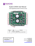
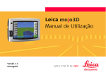
4.2 DIP Switch
The switch is used to identify card number, default setting is
card 15. There are two methods to set the card number:
a. PnP mode
Just plug in PCI bus adapter into PCI slot, the PCI BIOS will
allocate I/O address to each adapter automatically and assign
card number start from 0 to each adapter. You may set any
card number at PnP mode, and you need use software tools
to distinguish port id. Almost all of the operating systems run
at PnP mode.
7
8
DECISION Computer International
Operations Manual
PCI bus multi-8255/8254 adapter
Operations Manual
PCI bus multi-8255/8254 adapter
b. manual mode
Set card number by card identifier switch, the PCI BIOS will
assign pre-allocated I/O address to each adapter. Please set
different card number to each adapter (do not duplicate card
number setting).
1
2
3
4
OFF
OFF
OFF
OFF
Card Number
15
ON
OFF
OFF
OFF
14
OFF
ON
OFF
OFF
13
ON
ON
OFF
OFF
12
OFF
OFF
ON
OFF
11
ON
OFF
ON
OFF
10
OFF
ON
ON
OFF
9
ON
ON
ON
OFF
8
OFF
OFF
OFF
ON
7
ON
OFF
OFF
ON
6
OFF
ON
OFF
ON
5
ON
ON
OFF
ON
4
OFF
OFF
ON
ON
3
ON
OFF
ON
ON
2
OFF
ON
ON
ON
1
ON
ON
ON
ON
0
) The card number starts from 0 to 15.
.
DECISION Computer International
9
10 DECISION Computer International
Operations Manual
PCI bus multi-8255/8254 adapter
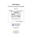
The signals assignment are shown in the following, where A is
the signals assignment of DB50 connector on the flat cable, and
the signals assignment of on board connector, and DB is the
signals assignment of university connector of Sub-D50.
When you like to connect Sub-D50 connector to DB50
connector, please use DB. The pin to pin assigned is shown as
DB vs. A.
Sample:
A Function
1
P3A0
3
P3A2
PCI bus multi-8255/8254 adapter
1. Connector Pin Assignments (JP1) U1/U2
DB A Function
DB
A Function
4.3 Pin Assignments
DB
1
18
Operations Manual
DB
34
2
A Function
2
P3A1
4
P3A3
For the DB37 connector, the pin assignments of 40 pin flat
cable is mark as A.
The pin assignments are shown in the next pages.
DECISION Computer International
11
1
18
35
3
20
37
5
22
39
7
24
41
9
26
43
11
28
45
13
30
47
15
32
49
17
1
3
5
7
9
11
13
15
17
19
21
23
25
27
29
31
33
35
37
39
41
43
45
47
49
P1A0
P1A2
P1A4
P1A6
P1B0
P1B2
P1B4
P1B6
P1C0
P1C2
P1C4
P1C6
GND
P2A0
P2A2
P2A4
P2A6
P2B0
P2B2
P2B4
P2B6
P2C0
P2C2
P2C4
P2C6
34
2
19
36
4
21
38
6
23
40
8
25
42
10
27
44
12
29
46
14
31
48
16
33
50
2
4
6
8
10
12
14
16
18
20
22
24
26
28
30
32
34
36
38
40
42
44
46
48
50
12 DECISION Computer International
P1A1
P1A3
P1A5
P1A7
P1B1
P1B3
P1B5
P1B7
P1C1
P1C3
P1C5
P1C7
GND
P2A1
P2A3
P2A5
P2A7
P2B1
P2B3
P2B5
P2B7
P2C1
P2C3
P2C5
P2C7
Operations Manual
PCI bus multi-8255/8254 adapter
2. Connector Pin Assignments (JP2) U3/U4
DB
A Function
DB
A Function
1
1
P3A0
34
2
P3A1
18
3
P3A2
2
4
P3A3
35
5
P3A4
19
6
P3A5
3
7
P3A6
36
8
P3A7
20
9
P3B0
4
10
P3B1
37
11
P3B2
21
12
P3B3
5
13
P3B4
38
14
P3B5
22
15
P3B6
6
16
P3B7
39
17
P3C0
23
18
P3C1
7
19
P3C2
40
20
P3C3
24
21
P3C4
8
22
P3C5
41
23
P3C6
25
24
P3C7
9
25
GND
42
26
GND
26
27
P4A0
10
28
P4A1
43
29
P4A2
27
30
P4A3
11
31
P4A4
44
32
P4A5
28
33
P4A6
12
34
P4A7
45
35
P4B0
29
36
P4B1
13
37
P4B2
46
38
P4B3
30
39
P4B4
14
40
P4B5
47
41
P4B6
31
42
P4B7
15
43
P4C0
48
44
P4C1
32
45
P4C2
16
46
P4C3
49
47
P4C4
33
48
P4C5
17
49
P4C6
50
50
P4C7
DECISION Computer International
Operations Manual
PCI bus multi-8255/8254 adapter
Connector Pin Assignments (JP3)
DB
A Function
1
1
P5A0
18
3
P5A2
35
5
P5A4
3
7
P5A6
20
9
P5B0
37
11
P5B2
5
13
P5B4
22
15
P5B6
39
17
P5C0
7
19
P5C2
24
21
P5C4
41
23
P5C6
9
25
GND
26
27
P6A0
43
29
P6A2
11
31
P6A4
28
33
P6A6
45
35
P6B0
13
37
P6B2
30
39
P6B4
47
41
P6B6
15
43
P6C0
32
45
P6C2
49
47
P6C4
17
49
P6C6
13
U5/U6
DB
A Function
34
2
P5A1
2
4
P5A3
19
6
P5A5
36
8
P5A7
4
10 P5B1
21
12 P5B3
38
14 P5B5
6
16 P5B7
23
18 P5C1
40
20 P5C3
8
22 P5C5
25
24 P5C7
42
26 GND
10
28 P6A1
27
30 P6A3
44
32 P6A5
12
34 P6A7
29
36 P6B1
46
38 P6B3
14
40 P6B5
31
42 P6B7
48
44 P6C1
16
46 P6C3
33
48 P6C5
50
50 P6C7
14 DECISION Computer International
Operations Manual
PCI bus multi-8255/8254 adapter
3. Connector Pin Assignments (JP4) U7/U8
DB
A Function
DB A Function
1
1
P7A0
34
2
P7A1
18
3
P7A2
2
4
P7A3
35
5
P7A4
19
6
P7A5
3
7
P7A6
36
8
P7A7
20
9
P7B0
4
10
P7B1
37
11
P7B2
21
12
P7B3
5
13
P7B4
38
14
P7B5
22
15
P7B6
6
16
P7B7
39
17
P7C0
23
18
P7C1
7
19
P7C2
40
20
P7C3
24
21
P7C4
8
22
P7C5
41
23
P7C6
25
24
P7C7
9
25
GND
42
26
GND
26
27
P8A0
10
28
P8A1
43
29
P8A2
27
30
P8A3
11
31
P8A4
44
32
P8A5
28
33
P8A6
12
34
P8A7
45
35
P8B0
29
36
P8B1
13
37
P8B2
46
38
P8B3
30
39
P8B4
14
40
P8B5
47
41
P8B6
31
42
P8B7
15
43
P8C0
48
44
P8C1
32
45
P8C2
16
46
P8C3
49
47
P8C4
33
48
P8C5
17
49
P8C6
50
50
P8C7
DECISION Computer International
Operations Manual
PCI bus multi-8255/8254 adapter
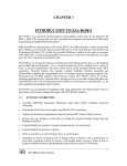
Connector Pin Assignments (DB37) U16/U17
DB A Function
DB
A Function
1
1
21
4
2
3
OUT0
22
6
OUT5
3
5 GATE0
23
8 GATE5
4
7
CLK0
24
10 CLK5
5
9
25
12
6
11 OUT1
26
14
+5V
7
13 GATE1
27
16
8
15 CLK1
28
18
-12V
9
17
29
20
10 19 OUT2
30
22 +12V
11 21 GATE2
31
24
12 23 CLK2
32
26
-12V
13 25
33
28 5MHZ
14 27 OUT3
34
30 1MHZ
15 29 GATE3
35
32 500KHZ
16 31 CLK3
36
34 100KHZ
17 33
37
36
18 35 OUT4
19 37 GATE4
20
2
CLK4
15
16 DECISION Computer International
Operations Manual
PCI bus multi-8255/8254 adapter
CHAPTER 5
Operations Manual
PCI bus multi-8255/8254 adapter
CHAPTER 6
DII DEVICE DRIVER
DIAGNOSTIC
To install DII (Decision Industrial Interface) for Windows 95
and Windows NT, you may start the installation by running
SETUP.EXE supplied on this distribution CD. During
installation, the Setup application will install an icon into a new
program group in your start menu (default name: "Decision
Industrial Interface"). After DII is installed, please select
“Start” menu, then “Settings”, then “Control Panel”, then “Add
New Hardware” menu, then select PCI multi-8255 card on the
“Industrial I/O Devices” hardware group.
In the following, we assume PCI BIOS allocates I/O address is
1B0.
The DII provides DLL, OCX, ... etc. components for further
programming. For more details, please refer DII manual.
DECISION Computer International
17
6.1 PASCAL Programming
program diagnostic(input, output);
uses Crt;
var a, i, test : integer;
procedure subtest;
begin
for i := 0 to 2 do
port[test+i] := a;
end;
begin
{ 8255 I/O Card Testing Program }
clrscr;
gotoxy(10, 10);
writeln('8255 I/O CARD TESTING');
gotoxy(10, 12);
writeln('TWO 8255 PORT A,B,C OUTPUT SQUARE
WAVE');
gotoxy(10, 14);
writeln('8253 COUNTER 0 DIVIDE BY 2');
gotoxy(10, 16);
writeln(' COUNTER 1 DIVIDE BY 50');
gotoxy(10, 18);
writeln(' COUNTER 2 DIVIDE BY 100');
{ 8253 Testing }
18 DECISION Computer International
Operations Manual
PCI bus multi-8255/8254 adapter
test := $1B0;
port[test+11] := $36;
port[test+11] := $76;
port[test+11] := $B6;
port[test+ 8] := $02; port[test+ 8] := $0;
port[test+ 9] := $32; port[test+ 9] := $0;
port[test+10] := $64; port[test+10] := $0;
repeat
test := $1B0;
port[test+3] := $80;
a := 0;
subtest;
for i := 0 to 1000 do;
a := $ff; subtest;
test := test + 4;
port[test+3] := $80;
a := 0;
subtest;
for i := 0 to 1000 do;
a := $ff;
subtest
until keypressed;
end.
Operations Manual
PCI bus multi-8255/8254 adapter
6.2 C Programming
#include <stdio.h>
#include <conio.h>
int test,i,a;
void subtest()
{
for(i=0;i<=2;i++) outportb(test+i,a);
}
main()
{
clrscr();
gotoxy(10,10);
puts("8255 I/O CARD TESTING");
gotoxy(10,12);
puts("TWO 8255 PORT A,B,C OUTPUT SQUARE WAVE");
gotoxy(10,14);
puts("8253 COUNTER 0 DIVIDE BY 2");
gotoxy(10,16);
puts("8253 COUNTER 1 DIVIDE BY 50");
gotoxy(10,18);
puts("8253 COUNTER 2 DIVIDE BY 100");
test = 0x1b0;
outportb(test+11,0x36);
outportb(test+11,0x76);
outportb(test+11,0xb6);
outportb(test+ 8,0x02);
outportb(test+ 8,0x00);
outportb(test+ 9,0x32);
outportb(test+ 9,0x00);
outportb(test+10,0x64);
outportb(test+10,0x00);
do {
test = 0x1b0;
outportb(test+3,0x80);
a = 0;
subtest();
for(i=0;i<=1000;i++);
a = 0xff;
subtest();
} while(!kbhit());
}
DECISION Computer International
19
20 DECISION Computer International
Operations Manual
PCI bus multi-8255/8254 adapter
Operations Manual
PCI bus multi-8255/8254 adapter
APPENDIX A
A.2 Warranty Information
WARRANTY INFORMATION
A.1 Copyright
Copyright
2002,
2003
DECISION
COMPUTER
INTERNATIONAL CO., LTD. All rights reserved. No part of
PCI bus 8255 adapter software and manual may be reproduced,
transmitted, transcribed, or translated into any language or
computer language, in any form or by any means, electronic,
mechanical, magnetic, optical, chemical, manual, or otherwise,
without the prior written permission of DECISION
COMPUTER INTERNATIONAL CO., LTD.
Each piece of PCI bus 8255 adapter package permits user to
use PCI bus 8255 adapter only on a single computer, a
registered user may use the program on a different computer,
but may not use the program on more than one computer at the
same time.
Corporate licensing agreements allow duplication and
distribution of specific number of copies within the licensed
institution. Duplication of multiple copies is not allowed except
through execution of a licensing agreement. Welcome call for
details.
DECISION warrants that for a period of one year from the date
of purchase (unless otherwise specified in the warranty card)
that the goods supplied will perform according to the
specifications defined in the user manual. Furthermore that the
PCI bus 8255 adapter product will be supplied free from
defects in materials and workmanship and be fully functional
under normal usage.
In the event of the failure of a PCI bus 8255 adapter product
within the specified warranty period, DECISION will, at its
option, replace or repair the item at no additional charge. This
limited warranty does not cover damage resulting from
incorrect use, electrical interference, accident, or modification
of the product.
All goods returned for warranty repair must have the serial
number intact. Goods without serial numbers attached will not
be covered by the warranty.
Transportation costs for goods returned must be paid by the
purchaser. Repaired goods will be dispatched at the expense of
PCI bus 8255 adapter.
To ensure that your PCI bus 8255 adapter product is covered by
the warranty provisions, it is necessary that you return the
Warranty card.
Under this Limited Warranty, DECISION's obligations will be
limited to repair or replacement only, of goods found to be
defective as specified above during the warranty period.
DECISION Computer International
21
22 DECISION Computer International
Operations Manual
PCI bus multi-8255/8254 adapter
DECISION is not liable to the purchaser for any damages or
losses of any kind, through the use of, or inability to use, the
PCI bus 8255 adapter product.
DECISION reserves the right to determine what constitutes
warranty repair or replacement.
Operations Manual
PCI bus multi-8255/8254 adapter
APPENDIX B
DATA SHEET
Please put the data sheet that copy from DCI Smartlab
8255/8253 I/O card.
Return Authorization: It is necessary that any returned goods
are clearly marked with an RA number that has been issued by
DECISION. Goods returned without this authorization will not
be attended to.
DECISION Computer International
23
24 DECISION Computer International