1
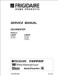
TABLE OF CONTENTS SAFE SERVICING PRACTICES - ALL APPLIANCES...... 2 INTRODUCTION Electrical Information ..................................................................................................................... 03. Compressor Information ................................................................................................................. 03. REFRIGERANT SYSTEM SERVICE INSTRUCTIONS Definitions ....................................................................................................................................... 04 Recovery ................................................................................................................................... 04 Recycling .................................................................................................................................. 04 Reclaim...................................................................................................................................... 04 Safety Warnings ................................................................................................................ .............. 04 Compressor Testing ................................................................................................................. 04 Charging Sealed Systems ....................................................................................................... 04 Soldering .................................................................................................................................... 04-05 Sealed System ................................................................................................................................. 05 Sealed System Diagnosis Undercharged System ............................................................................................................. 05 Overcharged System ............................................................................................................... 05 Pressure Equalizing (System Unloading) .............................................................................. 05 Refrigerant Leaks ................................................................................................................ 05-06 Component Replacement............................................................................................................... 06 Compressor Replacement ............................................................................................................. 06 To Flush The System ............................................................................................................... 06 To Use Refrigerant To Flush The System .............................................................................. 06 Installing a New Compressor ............................................................................................. 06-07 Evacuating & Recharging .............................................................................................................. 07 Equipment Needed ................................................................................................................... 07 Installing Evacuation & Recharging Equipment ................................................................... 07 Evacuating System .................................................................................................................. 07 Charging The System .............................................................................................................. 07 Final Leak Test .......................................................................................................................... 07 WIRING DIAGRAMS - SPECIFICATION Electrical Wiring Diagrams Two Speed Fan - Models with Rotary Compressors ............................................................. 08 Dehumidifier Specification Model FDL25P........................................................................................................................... 09 Model FDL45P........................................................................................................................... 10 Model FDK45P........................................................................................................................... 11 Model FDL60P........................................................................................................................... 12 Model FDK60P........................................................................................................................... 12 Compressor Overload Data and Restrictor tube data........................................................... 13 Fan Location Diagram.............................................................................................................. 14 1 SAFE SERVICING PRACTICES - ALL APPLIANCES To avoid personal injury and/or property damage, it is important that Safe Servicing Practices be observed. The following are some limited examples of safe practices: 1. DO NOT attempt a product repair if you have any doubts as to your ability to complete it in a safe and satisfactory manner. 2. Before servicing or moving an appliance: Remove the power cord from the electrical outlet, trip the circuit breaker to the OFF position, or remove the fuse Turn off the gas supply Turn off the water supply 3. Never interfere with the proper operation of any safety device. 4. USE ONLY REPLACEMENT PARTS CATALOGED FOR THIS APPLIANCE. SUBSTITUTIONS MAY DEFEAT COMPLIANCE WITH SAFETY STANDARDS SET FOR HOME APPLIANCES. 5. GROUNDING: The standard color coding for safety ground wires is GREEN, or GREEN with YELLOW STRIPES. Ground leads are not to be used as current carrying conductors. It is EXTREMELY important that the service technician reestablish all safety grounds prior to completion of service. Failure to do so will create a hazard. 6. Prior to returning the product to service, ensure that: All electrical connections are correct and secure All electrical leads are properly dressed and secured away from sharp edges, high-temperature components, and moving parts All non-insulated electrical terminals, connectors, heaters, etc. are adequately spaced away from all metal parts and panels All safety grounds (both internal and external) are correctly and securely connected All panels are properly and securely reassembled WARNING This service manual is intended for use by persons having electrical and mechnical training and a level of knowledge of these subjects generally considered acceptable in the appliance repair trade. Electrolux cannot be responsible, nor assume any liability, for injury or damage of any kind arising from the use of this manual. 2 Electrical Information The Dehumidifier must be plugged into a 115 Volt, 60 Hz, AC only electrical outlet. The circuit should be protected by a 15 Amp circuit breaker or 15 amp time-delay type fuse. CAUTION: If voltage varies by ±10% of 115 volts, performance of the Dehumidifier may be affected. Operating the Dehumidifier with insufficient power can damage the compressor. The Dehumidifier power cord is equipped with a three prong grounding plug. It must be plugged directly into a properly grounded three prong receptacle. The receptacle must be installed in accordance with local codes and ordinances. A power cord about 6 feet long permits locating a unit suitably in most homes without the use of an extension cord. An extension cord can become a shock hazard if it rests on a damp floor or if water spills on it. Do not use an extension cord or an adapter plug. CAUTION: Replacement compressors are charged with oil at the factory. Care should be exercized when replacing a compressor to avoid spilling any oil. Rotary compressor hold down nuts must be torqued to 35 in/lbs to prevent loosening. 3 REFRIGERATION SYSTEM & SERVICE NOTICE: Instructions given here are furnished as a guide. Persons attempting to use these instructions to make repairs to the sealed refrigeration system should have a working knowledge of refrigeration, previous training on sealed system repair, and an EPA certification for servicing refrigeration systems. IMPORTANT NOTICE Effective July 1, 1992, the United States clean air act governs the disposal of refrigerants such as R-22. Therefore, when discharging or purging the sealed system, use an EPA approved refrigerant recovery system as outlined in the final rule on the protection of stratospheric ozone and refrigerant recycling which was published in the Federal Register May 14, 1993. NOTE: Frigidaire does not permit the use of recovered refrigerant in the servicing of our products for in-warranty and out-of-warranty repairs or for products covered by service contracts. Therefore, only new refrigerant or refrigerant that has been reclaimed back to new specifications by a refrigerant manufacturer is to be used. followed by a sequence of circumstances, can lead to the compressor shell seam separating. DEFINITIONS Recovery: to remove refrigerant in any condition from a system and store it in an external container without necessarily testing or processing it in any way. A hydraulic block then occurs, preventing the compressor from starting. This condition is known as locked rotor. Electric current continues to flow through the compressor motor windings which become, in effect, electric resistance heaters. The heat produced begins to vaporize the excess refrigerant liquid, causing a rapid increase in system pressure. If the compressor protective devices fail, the pressure within the system may rise to extremes far in excess of the design limits. Under these conditions, the weld seam around the compressor shell can separate with explosive force, spewing oil and refrigerant vapor which could ignite. Recycling: to clean refrigerant for reuse by oil separation and single or multiple passes through devices, such as replaceable core filter-driers, which reduce moisture, acidity and particulate matter. This term usually applies to procedures implemented at the field job site or at a local service shop. Reclaim: to reprocess refrigerant to new product specifications by means which may include distillation. Will require chemical analysis of the refrigerant to determine that appropriate product specifications are met. This term usually implies the use of processes or procedures available only at a reprocessing or manufacturing facility. To eliminate this exceedingly rare but potential hazard, never add refrigerant to a sealed system. If refrigerant is required, evacuate the existing charge and recharge with the correct measured amount of the refrigerant specified for the system. SAFETY WARNINGS SOLDERING Compressor Testing WARNING: WEAR APPROVED SAFETY GLASSES WHEN WORKING WITH OR ON ANY PRESSURIZED SYSTEM OR EQUIPMENT. HAVE AN APPROVED DRY TYPE FIRE EXTINGUISHER HANDY WHEN USING ANY TYPE OF GAS OPERATED TORCH. Whenever testing a compressor, extreme caution should be used to prevent damaging the terminals. A compressor with a damaged terminal or a grounded winding can expel a terminal from its insulated housing when the compressor is energized. If this happens, a mixture of refrigerant and oil will be released that could be ignited by an external heat source (open flame, heater, etc.). Also, if there is air in the system when this happens, a spark at the compressor shell could ignite the refrigerant and oil mixture. 1. All joints to be soldered must have proper fit. Clearance between tubes to be soldered should be from .001 to .006. It is not practical to actually measure this; however, you do not want dry fit or loose fit. Tubing joints should overlap about distance of their diameter except for restrictor tubes, which should be inserted 1.25 2. Clean all joint areas with fine steel wool or, preferably, abrasive cloth, such as grit cloth No. 23 or Scotch-Brite. Charging Sealed Systems Overcharging a refrigeration system with refrigerant can be dangerous. If the overcharge is sufficient to immerse the major parts of the motor and compressor in liquid refrigerant, a situation has been created which, when 4 Overcharged System 3. Apply thin film of liquid flux recommended for silver soldering to surfaces to be joined, and to surfaces immediately adjacent to joint. 4. Align tubing so no stress is on joint. Do not move tubing while solder is solidifying or leaks will result. Operate the unit for at least 30 minutes in a room temperature of 75°F to 85°F. The top of the compressor should be warm to the touch. This applies to a reciprocating compressor only. If it is cool or cold, the system is possibly overcharged. On models eqipped with Rotary compressors, check for frost or cold temperatures all the way to the top of the accumulator. CAUTION: During application of heat, use wet cloths to prevent heat from conducting to areas other than soldered joint. Use a sheet of metal as a heat deflector to keep flame away from flammable materials and painted surfaces. An overcharged system must be evacuated and recharged. Purging off excess refrigerant is not legal or practical, as there is no way of determining the amount to purge. 5. Use torch of adequate capacity so joint can be quickly heated with minimum of heat travel to other points. Use good grade of silver solder. 6. Solder connections. If tubing is properly cleaned and fluxed, solder will flow readily. Use only enough solder to make a good bond. 7. Allow joint to cool, then wash exterior with water to remove flux. Pressure Equalizing (System Unloading) If an attempt is made to start the unit too soon after it has stopped, the compressor may fail to start and will cycle on the overload protector. This is caused by high head pressure and low suction pressure. Allow the pressures to equalize through the capillary tube. Pressure equalizing (system unloading) will usually take 2 to 3 minutes. SEALED SYSTEM Refrigerant Leaks The dehumidifying system is similiar to that of a room air conditioner, except for size. The condenser and evaporator are both fin and tube coils of copper tubing with aluminum fins. Both coils are placed in the air stream. An undercharge of refrigerant is usually caused by a leak in the system. Such leaks must be located, the refrigerant recovered, and the leak repaired before evacuating and recharging. Simply adding the refrigerant or recharging will not permanently correct the problem and may lead to a compressor burn out. A capillary tube controls the refrigerant flow from the condenser to the evaporator. The suction tube from the evaporator outlet to the compressor is insulated to prevent sweating. NOTE: Do not replace a component because the system is undercharged unless a nonrepairable leak is found within the system components. NOTE: Check the performance of the dehumidifier and electrical system before attempting to repair the sealed system. If a leak cannot be readily found, the system should be pressurized to at least 75 psig (gauge pressure). If necessary, attach a ¼ line piercing valve to the compressor process tube and add enough refrigerant for testing. (Only use the refrigerant specified on the serial nameplate.) SEALED SYSTEM DIAGNOSIS Undercharged System Disconnect fan motor leads and start the unit. A slight, uniform film of frost should form on the entire evaporator within about 10 minutes. If it does not, the system is possibly undercharged. NOTE: The line piercing valve (clamp-on type) should be used for test purposes only. It must be removed from system after it has served its purpose. If an undercharged system is found, perform the following: Most leaks can be found with a Halide torch. However, for very small leaks, it may be necessary to use an Electronic Leak Detector, or the soap bubble method to pinpoint the leaks. Leak test unit. Recover refrigerant. Repair Leak. Evacuate and recharge unit with proper amount of refigeratant. CAUTION: Be sure the system has a positive pressure before using the soap bubble method of leak detecting. A vacuum within the system could draw in moisture and contaminants. NOTE: Always leak test system after recharging. After servicing a system, always leak test the entire system, especially new joints before final recharging. Clean off any soldering flux, if used, from the joints before 5 leak testing, as flux can seal off pinhole leaks that would show up later. CAUTION: The end of flushing hose of tank regulator must be equipped with a hand shut-off valve (Robinair No. 40380). Close hand shut-off valve and adjust nitrogen regulator to correct pressure before proceeding with flushing procedure. COMPONENT REPLACEMENT CAUTION: It is extremely important to verify the type of refrigerant in a system before starting any sealed system repair. Check serial plate for the correct refrigerant type and charge. To Use Refrigerant To Flush The System: CAUTION: Refrigerant used for flushing must be captured in a recovery bag. Meter amount of refrigerant used for flushing with your charging cylinder. DO NOT OVERFILL THE BAG. When replacing components, all copper joints must be joined with silver solder or Sil-Fos. CAUTION: Be careful not to damage adjacent parts when using a torch on soldered joints. If necessary, use a metal heat shield, or wrap a wet cloth around the tubing to reduce heat transfer. 1. Remove suction and discharge lines on compressor and disconnect capillary tube from condenser. Connect process coupling to outlet and inlet tube of condenser. 2. Connect hose to outlet process coupling and charging cylinder. Connect another hose to inlet coupling and recovery bag. 3. Open charging cylinder and allow refrigerant to flow through condenser until discharge into bag is clear. 4. Connect process fitting to compressor suction line. Flush evaporator and capillary tube. COMPRESSOR REPLACEMENT CAUTION: NEVER install a new compressor without first checking for possible system contamination. To check for contamination, obtain an oil sample from an old compressor. NOTE: If unable to get refrigerant flow through capillary tube, remove capillary tube from evaporator and flush again. If oil has burned odor, but no color change or residue follow instructions in section Installing A New Compressor on page 14. If oil has burned odor and shows contamination (dark color) or feels gritty follow instructions in next section, To Flush The System. Remove as much contamination as possible from system before installing new compressor. 5. If cap tube is blocked, replace cap tube. 6. Reassemble system. Installing a New Compressor All replacement compressors are shipped with rubber plugs in the suction, discharge, and process tubes and contain the correct oil charge and a holding charge of inert gas. Models with Reciprocating Compressors have a low-side process tube attached to the compressor shell. Models with Rotary Compressors have a process tube on the high side of the system soldered into the compressor discharge line To Flush The System NOTE: The system should be flushed with dry nitrogen. However, you must use R-22 if refrigerant is used to flush system. This is the only refrigerant that can be used to flush the system and it must be recovered. WARNING: DO NOT OPERATE COMPRESSOR WHEN CHARGING LIQUID REFRIGERANT INTO SYSTEM THROUGH ITS PROCESS TUBE. CAUTION: Use extreme care when using dry nitrogen to flush systems. Pressure in nitrogen cylinder could be as high as 2000 psi. Nitrogen cylinder must be equipped with approved pressure regulator and pressure relief valve. Ensure that your hoses have adequate ratings for pressure involved, and that all of your equipment is in good condition. Before installing the replacement compressor, remove the discharge plug and check for the pop sound of the inert gas leaving the compressor. CAUTION: DO NOT use compressor if you do not hear this sound. A new compressor which is cold (e.g. after having been kept in a cold service van) should be left to warm to the surrounding temperature before the plugs on the compressor connections are removed. This will help prevent condensation from forming 6 in the oil and the compressor. Also, avoid opening the system when any of the components or lines are cold. CAUTION: Release holding charge (release slowly to avoid oil discharge) on new compressor to ensure that there is no leak in seam or tubing. Then, reinstall rubber plug. Installing Evacuation and Recharging Equipment 1. Disconnect dehumidifier from electrical supply. 2. Install process tube adaptor on process tube leaving as much tube as possible. 3. Attach refrigeration service gauge manifold to system in following order: Low-side (compound gauge) to process tube Center port manifold hose before hand shut-off valve to charging cylinder. Center port manifold hose after hand shut-off valve to vacuum pump. Evacuating System To achieve the required levels of evacuation, a properly maintained two- stage vacuum pump in good condition is required. It is absolutely essential to maintain your vacuum pump according to the manufacturers instructions including required oil changes at the recommended intervals. Vacuum pump oil should always be changed after evacuating a contaminated system. Vacuum pump performance should be checked periodically with a micron gauge. 1. Make certain that charging cylinder valve, hand shut-off valve, and manifold gauge valves are closed. 2. Start vacuum pump. 3. Open hand shut-off valve and slowly open manifold valve, turning counterclockwise, for two full rotations. CAUTION: If high vacuum equipment is used, just crack manifold valve for a few minutes, then open slowly for two full turns, counterclockwise. This will prevent the compressor oil from foaming and being drawn into the vacuum pump. 4. Operate vacuum pump for minimum of 30 minutes to attain minimum of 29.9 (500 micron) vacuum or until vacuum of 500 microns is obtained.. 5. Close hand shut-off valve to vacuum pump. Watch compound gauge for several minutes. If reading rises, there is leak in system, go to step 6. If no leak is indicated, stop vacuum pump. System is now ready for charging. 6. If leak is indicated, stop vacuum pump and introduce small charge of refrigerant into system by cracking valve on bottom of charging cylinder until system is pressurized to 40 or 50 psig. 7. Leak test low-side. Close compound gauge. Run compressor for few minutes and leak test highside. When leak is found, recapture refrigerant using EPA approved recovery system, repair and go back to step 1. 7 Charging The System CAUTION: After charging the system with liquid, be certain to wait at least 5 minutes before starting the compressor to give the refrigerant a chance to disperse throughout the system. Otherwise, the compressor could be damaged by attempting to pump excessive quantities of liquid. Preparing the Charging Cylinder: 1. Charging cylinder must have at least eight ounces more refrigerant than required charge. 2. Plug in cylinder heater and bring pressure up to 30 pounds above gauge pressure at ambient temperature. Maintain, but do not exceed, this 30 pound increase in gauge pressure during system charging. WARNING: DO NOT USE EXTERNAL HEAT SOURCE ON CYLINDER OR EXCEED MAXIMUM GAUGE PRESSURE ON CHARGING SYSTEM. To Charge System: 1. Make certain that hand shut-off valve to vacuum pump is closed. 2. Set charging cylinder scale to pressure indicated on cylinder pressure gauge. 3. Observe refrigerant level in sight glass. Subtract amount to be charged into system and note shut off point. 4. Open charging cylinder valve slowly and allow proper charge to enter system. 5. As soon as refrigerant in sight glass has gone down to predetermined level, close charging cylinder valve. WARNING: DISCONNECT THE CHARGING CYLINDER HEATER AT THIS TIME TO PREVENT THE CYLINDER PRESSURE FROM EXCEEDING ITS MAXIMUM LIMITS. 6. Allow system to sit for five minutes. 7. Turn on dehumidifier compressor. Run compressor for few minutes and monitor system pressures. 8. When satisfied that unit is operating correctly, clamp process tube with pinchoff tool while unit is still running. 9. Remove process tube adaptor and solder the process tube closed. 11.Turn on unit. After few minutes, check process tubes for refrigerant leaks. FINAL LEAK TEST 1. With dehumidifier turned OFF, leak test all low-side system components. 2. Turn unit ON and run until condenser is warm. Leak test high-side system components. Wiring diagram 2202609108 CN2 CN3 YELLOW HIGH FAN N P1 WHITE TRANS. LOW P2 FAN 4 SHINE BOARD CN4 CN1 3 BLUE BLUE BLUE BLACK FAN WATER SWITCH RED BLACK WHITE YELLOW HUMIDITY SENSOR PIPE SENSOR CAP Y&G C COMP. N L BLACK BLUE WHITE GREEN POWER IN Wiring diagram 2202619052 CN2 CN3 P1 LOW P2 FAN 4 CN4 CN1 3 RED BLACK WATER SWITCH BLUE BLUE BLUE BLACK FAN BLUE L BLACK WHITE C COMP. R S C-CAP BLUE GREEN POWER IN 8 BLACK OVERLOAD BLACK CAP N SHINE BOARD HUMIDITY SENSOR WHITE YELLOW N YELLOW HIGH FAN WHITE TRANS. Y&G PIPE SENSOR FRIGIDAIRE MODEL SPECIFICATIONS Model Chassis type FDL25P11 FDL25P12 Dehumidifier Dehumidifier Capacity features Moisture Removal 25 25 EEV (L/kW.h) 1.3 1.3 17 (8) 17 (8) Voltage 115 115 Amps 3.9 3.9 Watts 370 370 Fuse/Breaker (Amps) 13 13 Receptacle Type NEMA 5-15 NEMA 5-15 Power Cord Number 2242609021 2242609021 13 13 2202609108 Page 08 2202609108 Page 08 2.5/450 2.5/450 Tank Volume Pints (L) Electrical Information Power Cord Amps Min Wiring Diagram Page # Air Flow System Capacitor-µ farads Fan Motor Mfg. Fan Motor Number Weiling Dayang 2240047025 2240047026 1200/220 1200/220 - - 1100/200 1100/200 RPM/CMP (EVAP) High Medium Low Refrigeration System Compressor Mfg. LG, Korea LG, Korea Compressor Number LX72HACG LX72HACG Compressor Type Rotary Rotary Overload Protector 2140162040 2140162040 Capacitor-µ farads 35/250 35/250 Refrigerant Charge 7.4 7.4 2162609025 2162609025 Electronic Electronic - - Restrictor Tube Thermostat Type Control Thermostat Location Diagram Condenser Fan and Evaporator Blower Location Diagram Page 14 Page 14 9 FRIGIDAIRE MODEL SPECIFICATIONS Model Chassis type FDL45P11 FDL45P12 FDL45P13 FDL45P14 Dehumidifier Dehumidifier Dehumidifier Dehumidifier Capacity features Moisture Removal 45 45 45 45 EEV (L/kW.h) 1.5 1.5 1.5 1.5 17 (8) 17 (8) 17 (8) 17 (8) Voltage 115 115 115 115 Amps 4.5 4.5 4.5 4.5 Watts 530 530 530 530 Fuse/Breaker (Amps) 13 13 13 13 Receptacle Type NEMA 5-15 NEMA 5-15 NEMA 5-15 NEMA 5-15 Power Cord Number 2242609021 2242609021 2242609021 2242609021 13 13 13 13 2202619052 Page 08 2202619052 Page 08 2202619052 Page 08 2202619052 Page 0 8 3/450 3/450 3/450 3/450 Tank Volume Pints (L) Electrical Information Power Cord Amps Min Wiring Diagram Page # Air Flow System Capacitor-µ farads Fan Motor Mfg. Fan Motor Number Weiling Dayang Weiling Dayang 2240047025 2240047026 2240047025 2240047026 1300/250 1300/250 1300/250 1300/250 - - - - 1200/210 1200/210 1200/210 1200/210 RPM/CMP (EVAP) High Medium Low Refrigeration System Compressor Mfg. Compressor Number Shenlin, Shanghai Shenlin, Shanghai Shenlin, Shanghai Shenlin, Shanghai KH074WLHC KH074WLHC SD074SW-P3BU SD074SW-P3BU Compressor Type Rotary Rotary Rotary Rotary Overload Protector 2140131050 2140131050 2140131250 2140131250 Capacitor-µ farads 35/250 35/250 35/250 35/250 Refrigerant Charge 11.4 11.4 11.4 11.4 2162619084 2162619084 2162619206 2162619206 Electronic Electronic Electronic Electronic - - - - Restrictor Tube Thermostat Type Control Thermostat Location Diagram Condenser Fan and Evaporator Blower Location Diagram Page 14 Page 14 10 Page 14 Page 14 FRIGIDAIRE MODEL SPECIFICATIONS Model Chassis type FDK45P11 FDK45P12 FDK45P13 FDK45P14 Dehumidifier Dehumidifier Dehumidifier Dehumidifier Capacity features Moisture Removal 45 45 45 45 EEV (L/kW.h) 1.5 1.5 1.5 1.5 17 (8) 17 (8) 17 (8) 17 (8) Voltage 115 115 115 115 Amps 4.5 4.5 4.5 4.5 Watts 530 530 530 530 Fuse/Breaker (Amps) 13 13 13 13 Receptacle Type NEMA 5-15 NEMA 5-15 NEMA 5-15 NEMA 5-15 Power Cord Number 2242609021 2242609021 2242609021 2242609021 13 13 13 13 2202619052 Page 08 2202619052 Page 08 2202619052 Page 08 2202619052 Page 08 3/450 3/450 3/450 3/450 Tank Volume Pints (L) Electrical Information Power Cord Amps Min Wiring Diagram Page # Air Flow System Capacitor-µ farads Fan Motor Mfg. Fan Motor Number Weiling Dayang Weiling Dayang 2240047025 2240047026 2240047025 2240047026 1300/250 1300/250 1300/250 1300/250 - - - - 1200/210 1200/210 1200/210 1200/210 RPM/CMP (EVAP) High Medium Low Refrigeration System Compressor Mfg. Compressor Number Shenlin, Shanghai Shenlin, Shanghai Shenlin, Shanghai Shenlin, Shanghai KH074WLHC KH074WLHC SD074SW-P3BU SD074SW-P3BU Compressor Type Rotary Rotary Rotary Rotary Overload Protector 2140131050 2140131050 2140131250 2140131250 Capacitor-µ farads 35/250 35/250 35/250 35/250 Refrigerant Charge 11.4 11.4 11.4 11.4 2162619084 2162619084 2162619206 2162619206 Electronic Electronic Electronic Electronic - - - - Restrictor Tube Thermostat Type Control Thermostat Location Diagram Condenser Fan and Evaporator Blower Location Diagram Page 14 Page 14 11 Page 14 Page 14 FRIGIDAIRE MODEL SPECIFICATIONS Model Chassis type FDL60P11 FDL60P12 FDK60P11 FDK60P12 Dehumidifier Dehumidifier Dehumidifier Dehumidifier Capacity features Moisture Removal 60 60 60 60 EEV (L/kW.h) 1.5 1.5 1.5 1.5 17 (8) 17 (8) 17 (8) 17 (8) Voltage 115 115 115 115 Amps 6.3 6.3 6.3 6.3 Watts 730 730 730 730 Fuse/Breaker (Amps) 13 13 13 13 Receptacle Type NEMA 5-15 NEMA 5-15 NEMA 5-15 NEMA 5-15 Power Cord Number 2242609021 2242609021 2242609021 2242609021 13 13 13 13 2202619052 Page 08 2202619052 Page 08 2202619052 Page 08 2202619052 Page 08 3/450 3/450 3/450 3/450 Tank Volume Pints (L) Electrical Information Power Cord Amps Min Wiring Diagram Page # Air Flow System Capacitor-µ farads Fan Motor Mfg. Fan Motor Number Weiling Dayang Weiling Dayang 2240047025 2240047026 2240047025 2240047026 1300/250 1300/250 1300/250 1300/250 - - - - 1200/210 1200/210 1200/210 1200/210 RPM/CMP (EVAP) High Medium Low Refrigeration System Compressor Mfg. Shenlin, Shanghai Shenlin, Shanghai Shenlin, Shanghai Shenlin, Shanghai Compressor Number SD104SW-P3AU SD104SW-P3AU SD104SW-P3AU SD104SW-P3AU Compressor Type Rotary Rotary Rotary Rotary Overload Protector 2140131100 2140131100 2140131100 2140131100 Capacitor-µ farads 35/250 35/250 35/250 35/250 Refrigerant Charge 10.6 10.6 10.6 10.6 2162619080 2162619080 2162619080 2162619080 Electronic Electronic Electronic Electronic - - - - Restrictor Tube Thermostat Type Control Thermostat Location Diagram Condenser Fan and Evaporator Blower Location Diagram Page 14 Page 14 12 Page 14 Page 14 Used with compressor 2140162040 LX72HACG 4TM777VFB Opening Temp Closing Temp o o C±5 oC C±5 oC Test Amp 150+10/-5 21.5A 61±9 2140131050 KH074WLHC LOGN21A/BF900-KB 160±10 70±10 18A/22.5A 5~15Sec 2140131250 SD074SW-P3BU LOGN21A/BF900-KB 160±10 70±10 18A/22.5A 5~15Sec 2140131100 SD104SW-P3AU MRA98883-9200 160±10 70±10 22.5A 5~15Sec Part# Supplier part # Short Time Trip Opening Time - Sec 5~15Sec 13 Style # Length O.D. I.D. PSIG CFM Dry Air 2162609025 15.7 0.087 0.035 25 Min. 0.625 Max. 0.695 2162619084 47.2 0.098 0.051 15 0.974 1.045 2162619206 27.6 0.098 0.043 20 0.0685 0.0754 2162619080 35.4 0.098 0.051 15 1.130 1.200 Fan Location Diagram 14