1
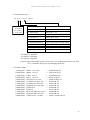
PM4C-06 SERIES
User's Manual
3073 (rev.1)
APPLICATION
OF
ELECTRONIC DEVICES
TSUJI ELECTRONICS CO.,LTD
3739 Kandatsu-machi Tsuchiura-city
Ibaraki-Pre 300-0013 Japan
Phone +81-(0)29-832-3031
Fax +81-(0)29-832-2662
URL http://www.tsujicon.jp
Contents
Contents
Contents............................................................................................................................................... 1
1.
Abstract................................................................................................................................... 2
1-1 Characteristics ........................................................................................................................ 2
1-2 Concept of PM4C-06 control ................................................................................................. 3
2.
Panel layout ............................................................................................................................ 4
2-1 Front panel ............................................................................................................................. 4
2-2 Rear panel............................................................................................................................... 7
3.
Setting the motor characteristics............................................................................................. 8
3-1 Setting Preparation and Completion ...................................................................................... 8
3-2 Setting items ........................................................................................................................... 9
4.
LOCAL mode driving........................................................................................................... 13
4-1 Select motor speed ............................................................................................................... 13
4-2 Motor driving mode selection .............................................................................................. 13
4-3 Channel selection ................................................................................................................. 13
4-4 Relative Index mode (REL) ................................................................................................. 14
4-5 Absolute index mode (ABS) ................................................................................................ 14
4-6 Home position stop mode (HP) ............................................................................................ 14
4-7 Continuous Stepping mode (SCAN) .................................................................................... 14
4-8 JOG step movement ............................................................................................................. 14
4-9 Preset position data .............................................................................................................. 14
4-10 Start driving motors at the same time ................................................................................... 14
4-11 Automatic hold-off ............................................................................................................... 14
4-12 Hand-box control (Optional) ................................................................................................ 15
5.
REMOTE mode driving ....................................................................................................... 16
5-1 Signals and Commands ........................................................................................................ 16
5-2 Communication standard...................................................................................................... 16
6.
Command in detail (LAN, RS232C, GP-IB) ........................................................................ 18
6-1 REMOTE/LOCAL command .............................................................................................. 18
6-2 SRQ command (SRQ signal is one of GP-IB signal lines.) ................................................. 18
6-3 Status read out command ..................................................................................................... 19
6-4 Motor control command ....................................................................................................... 20
6-5 Command for set and read out parameters ........................................................................... 22
6-6 Command for set and read out limit switch data parameters ............................................... 25
6-7 Others ................................................................................................................................... 26
7.
Firmware version up ............................................................................................................. 27
8.
Old command in detail (for LAN, RS232C, GP-IB) ............................................................ 29
8-1 "S1" command...................................................................................................................... 29
8-2 "S2" command...................................................................................................................... 30
8-3 "S3" command...................................................................................................................... 32
8-4 "S4" command...................................................................................................................... 34
8-5 "S7" command...................................................................................................................... 35
9.
Hand Box control (Optional) ................................................................................................ 36
10.
Data initialization ................................................................................................................. 37
11.
Additional function ............................................................................................................... 37
12.
Connection with outer equipment ........................................................................................ 38
13.
Performance and specifications ............................................................................................ 39
PM4C-06 series command list .......................................................................................................... 40
1
1.Abstract
1. Abstract
1-1 Characteristics
Can control 4 stepping motors at a time.
Can set individual characteristics.
Scan to set position by trapezoidal driving.
Absolute/Relative movement is available
Can stop when limit switch is detected.
Limit switch status can be set individually. (status : N.O/N.C, Enable/Disable)
Can stop by STOP button when scanning.
Step driving. (1 step : 0~9999 pulse)
Inching driving.
Continuous driving.
Enabled channels and their driving mode are shown in front panel LED lamp.
Detecting home position.
Can change driving mode. (mode : HP, REL, ABS, SCAN)
Stop mode when limit switch is on or STOP button is pressed is selectable. (mode: SLOW, EM)
Backup data over five years.
Can start driving motors synchronously.
Hand Box is useful for checking mechanical position.
Can choose one of the motors and drive it by JOG lever in Hand Box.
Can choose driving speed in Hand Box.
Each channel has LED lamps that indicate the status of limit switch and pulse-out.
Motor hold-off function for each channel.
If you start driving hold-off motors, automatically the hold-off mode is disabled and returns to
be enabled after motor stopping.
・ Motor hold-off can be set by remote command.
・ LAN, GP-IB (IEEE-488) and RS-232C communication port.
・
・
・
・
・
・
・
・
・
・
・
・
・
・
・
・
・
・
・
・
・
・
2
1.Abstract
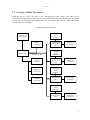
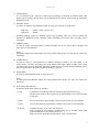
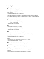
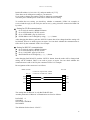
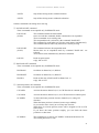
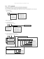
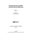
1-2 Concept of PM4C-06 control
PM4C-06 has five CPUs. One CPU is for controlling the whole system. The others are for
controlling the stepping motor and control each channel individually. Current positions, speed data,
acceleration rate in starting and stopping phase, etc. are stored in the memories. Those data can be
read and renewed at any time.
Schematics of internal circuit
8×2 line
LCD
indicator
P ush Button SW
LED Lamp
Data
M emory
M ain CPU
A POSITION
pulse control
CPU
M ain CPU Bus
8×2 line
LCD
indicator
LAN
com. port
B POSITION
pulse control
CPU
RS232C
com. port
8×2 line
LCD
indicator
GP-IB
com. port
C POSITION
pulse control
CPU
Pulse out
L.S input
Pulse out
L.S input
Pulse out
L.S input
8×2 line
LCD
indicator
D POSITION
pulse control
CPU
Pulse out
L.S input
3
2.Panel layout
2. Panel layout
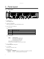
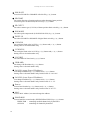
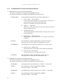
2-1
Front panel
① POWER button
Power supply switch
② Connector for Hand Box
When using Hand Box, connect the Hand Box cable.
③ Status LED and LCD indicator
Status LED
CWLS
CW
CCW
CCWLS
MF
HP
Clockwise Limit Switch. It turns on when limit switch (LS) is on.
Clockwise pulse output
Counter Clockwise pulse output
Counter Clockwise Limit Switch. It turns on when limit switch (LS) is on.
Motor Free signal. (= HOLD OFF) It turns on when the motor is hold-off.
Home Position switch. It turns on when the switch is on.
LCD indicator
Upper :
Lower :
current position
pulse output count (REL mode)
absolute position (ABS mode)
preset position (SCAN mode)
Those values can be changed by ④,⑤.
In SETUP mode, it displays items for system control.
④ (←), (→) button
It changes digit when setting data.
⑤ (+), (-) button
It increases or decreases value.
⑥ REMOTE button
It changes pulse control mode.
Light ON : REMOTE (control by command in LAN, RS232C, GP-IB)
Light OFF : LOCAL (control by button in Front panel)
4
2.Panel layout
⑦ SETUP button
It is for SETUP mode. Items for control can be changed or checked in SETUP mode. This
button can be used in LOCAL mode only. In SETUP mode, LOCAL mode cannot be changed to
REMOTE mode.
⑧ ENABLE button
It enables or disables each channel control. It can be used at LOCAL mode only.
Light ON :
Light OFF :
enable (JOG , SCAN , etc.)
disable
Scanning channel cannot be disabled. Please stop scanning when you want to disable the
channel. In REMOTE mode, channels whose ENABLE LED lamp does not light can be
controlled.
⑨ PRESET button
In LOCAL mode, current position in enabled channel can be set. Preset data is displayed at
lower part in LCD indicator.
Note)
If PRESET button and STOP button are being pushed when power on, all items for control are
initialized.
⑩ START button
14 . In
In LOCAL mode, it starts pulse-out of enabled channel in mode of ⑫ with speed ○
SCAN mode, it doesn’t start pulse-out but the button LED lights. When it lights, JOG switch
can starts pulse-out to its direction. When the START button is pressed during outputting pulses,
the start operation for the pulse-outputting channel is ignored.
⑪ STOP button
In LOCAL and REMOTE mode, it stops pulse-out.
Note)
If both STOP and PRESET button are being pushed when power on, items for control are
initialized.
⑫ RUN mode LED indicator
It indicates RUN mode. There are 4 modes.
1) H.P
: Continuous scan and stop at home position by home position sensor.
The direction (CW/CCW) of pulse-out in start should be set in SETUP mode
in advance.
2) REL
: move to the relative position that is shown at lower part in LCD indicator.
3) ABS
: move to the absolute position that is shown at lower part in LCD indicator.
4) SCAN
: Continuous pulse-out to CW/CCW direction.
After preparation for scanning (START lamp on) by START button, then
pulse-out direction is decided by JOG lever.
Pulse-out can be stopped by STOP button or LS (Limit Switch).
5
2.Panel layout
⑬ MODE button
In LOCAL mode, it changes RUN mode. Pressing it changes mode in order.
SCAN → ABS → REL → HP → SCAN
⑭ Speed select LED indicator
It indicates pulse-out speed. These are 3 modes.
1) H : Pulse-out in HSPD (Hi Speed)
*1)
2) M : Pulse-out in MSPD (Mid Speed)
*1)
3) L : Pulse-out in LSPD (Low Speed) *1)
*1)
HSPD, MSPD, LSPD are set in SETUP mode
⑮ SPEED button
It changes pulse-out speed.
⑯ JOG lever
It is for inching drive of enabled channel. Throwing on it starts pulse-out to the CW/CCW
direction. If throwing on it more than 0.5 seconds or after reaching pulse-out count of a JOG
step, pulse-out continues. Throwing off stops pulse out. The lever is not available in REMOTE
mode.
6
2.Panel layout
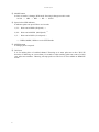
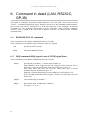
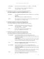
2-2
Rear panel
1
2
3
4
5
6
7
① Pulse output connector
Three signals are out from this connector, CW, CCW pulse and hold-off signal.
D-Sub 9P (socket type)
Details are section 11.
② External switch input connector
External switches (CW, CCW, Home position limit switch) are connected.
D-Sub 9P (pin type)
Details are section 11.
③ GP-IB
24P connector for GP-IB
④ RS232C
Connector for RS232C
D-Sub 9pin (pin type)
⑤ LAN
Connector for LAN (RJ-45)
⑥ Fuse Holder
For safety of AC power line.
If necessary, use 3A midget fuse.
⑦ AC100V/200V power supply connector
Inlet type AC connector for AC100V/200V power supply
Use attached AC cable.
7
3.Setting the motor characteristics
3. Setting the motor characteristics
The data of four stepping motors can be set and stored, which is kept by battery back up. The data
are kept until data-reset. The data realize accurate control for any system. In SETUP mode,
pulse-out is forbidden. The data cannot be set during motor moving.
3-1
Setting Preparation and Completion
When PM4C-06 is powered on, Firmware version is displayed in LCD indicator for a few seconds,
for example “PM4C-06 Ver 1.06”. (after Ver1.06)
After that, display changes to normal mode and you can use PM4C-06.
Setting values (REM/LOC, MODE, SPEED, etc.) are kept by battery backup.
a)
Go to LOCAL mode by REMOTE button. (REMOTE button LED turns off.)
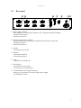
b)
Push SETUP button. (SETUP button LED turns on.)
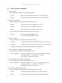
LCD indicators display Setting Item.
digit →
1
2
3
4
5
6
7
8
+
0
1
2
3
4
5
6
+
0
0
1 2 3
NORMAL
4
5
→
1
2
H
I
3
N
4
5
6
7
8
0
0
9
0
0
0
2
0
o
.
SETUP
You can change data by (+)/(-) button. Appearance of Cursor depends on setting item. When
the Cursor appears, you can change the position by (←)/(→) button. The item can be changed
by JOG. Lever.
See the order of items below.
HSPD → MSPD → LSPD → RATE → JOG PLS → LS EN/DA → LS NC/NO →
LS STOP FAST/SLOW → PB STOP FAST/SLOW → HOLD OFF EN/DA →
HP START CW/CCW → HP NC/NO → PULS MODE P-P/P-D → DIG LS EN/DA →
CW DIG LS → CCW DIG LS → 232C BAUD → GP-IB ADD → LAN IP1 →
LAN IP2 → PORT NO → MAC ADD → HAND BOX
232C BAUD ~ MAC ADD are common for each channel. So they are displayed only in “A”
channel LCD indicator. (MAC ADD is read-only.)
c)
8
Press SETUP button again, then LCD return to NORMAL mode. PM4C-06 starts running in a
new setting, except for "LAN IP:1", "LAN IP:2" and "Port no". If you change those setting,
power off PM4C-06 after returning to NORMAL mode, and power on again.
3.Setting the motor characteristics
3-2
Setting items
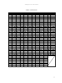
HI
Can set HSPD (hi speed) by (+)/(-) button.
< LCD >
Upper : velocity (5PPS~100,000PPS)
Lower : code (0~254)
Refer TABLE1.
The meaning of the code is same as PM4C-05(A).
When PPS is set by remote command, the value is displayed at Upper part in LCD indicator.
If you change code in Lower part by (+)/(-) button, PPS data is changed according to the code
data. Remote command only can set velocity from 1PPS to 100000PPS.
MI
Can set MSPD (mid speed) by (+)/(-) button.
< LCD >
Upper : velocity (5PPS~100,000PPS)
Lower : code (0~254)
The other setting is same as HSPD.
LO
Can set LSPD (low speed) by (+)/(-) button.
< LCD >
Upper : velocity (5PPS~100,000PPS)
Lower : code (0~254)
The other setting is same as HSPD.
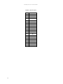
RT
Can set acceleration and deceleration rate by (+)/(-) button.
< LCD >
Upper : acceleration and deceleration rate. (1000ms/kHz~1ms/kHz)
Lower : code (0~21)
Refer TABLE2.
The meaning of the code is same as PM4C-05(A).
JOG
Can set minimum pulse output number of JOG lever by (+)/(-) button.
Setting value is decimal number. (0~9999)
LS.
Can select ENABLE or DISABLE of limit switch by (+)/(-) button.
LS.CNTCT
Can select contact type (N.C/N.O) of limit switch by (+)/(-) button.
LS.Stop
Can select stop mode (FAST/SLOW) of limit switch detection by (+)/(-) button.
PB.Stop
Can select stop mode (FAST/SLOW) of STOP button by (+)/(-) button.
9
3.Setting the motor characteristics
HOLD OFF
Can select ENABLE or DISABLE of hold-off by (+)/(-) button.
HP.START
Can set the direction of starting pulse-out when detecting home position.
Can select pulse-out direction (CW/CCW) by (+)/(-) button.
HP CNTCT
Can select contact type (N.C/N.O) of home position limit switch by (+)/(-) button.
PLS MODE
Can select pulse output mode (P-P 2PLS/P-D 1PLS) by (+)/(-) button.
DIGTL LS
Can select ENABLE or DISABLE of digital limit switch by (+)/(-) button.
CW DGLS
Can set digital limit value in CW by (+)/(-) button and (←)/(→) button.
Setting value is decimal number only.
CCW DGLS
Can set digital limit value in CCW by (+)/(-) button and (←)/(→) button.
Setting value is decimal number only.
232C BRT
Can select RS232C baud rate by (+)/(-) button.
GPIB ADD
Can change GP-IB address by (+)/(-) button.
Setting value is decimal number only.
LAN IP:1 (upper 2byte of IP address)
Can change IP address by (+)/(-) button and (←)/(→) button.
Setting value is decimal number only. Default value is "192.168."
LAN IP:2 (lower 2byte of IP address)
Can change IP address by (+)/(-) button and (←)/(→) button.
Setting value is decimal number only. Default value is ".1.55"
Port no
Can set Port Number by (+)/(-) button and (←)/(→) button.
Setting value is decimal number only. Default value is "07777".
MAC
Can see MAC address, but cannot change the address.
HAND BOX
Can set hand-box control mode (WHEN ENB/ALWAYS) by (+)/(-) button.
WHEN ENB : controlling enabled channel only by hand-box.
ALWAYS
: controlling all channel by hand-box.
10
3.Setting the motor characteristics
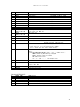
TABLE 1 SPEED DATA
No.
000
001
002
003
004
005
006
007
008
009
010
011
012
013
014
015
016
017
018
019
020
021
022
023
024
025
026
027
028
029
030
031
032
033
034
035
036
037
038
039
040
041
042
043
PPS
5
10
25
50
75
100
150
200
250
300
350
400
450
500
550
600
650
700
750
800
900
1000
1100
1200
1300
1400
1500
1600
1700
1800
1900
2000
2100
2200
2300
2400
2500
2600
2700
2800
2900
3000
3100
3200
No.
044
045
046
047
048
049
050
051
052
053
054
055
056
057
058
059
060
061
062
063
064
065
066
067
068
069
070
071
072
073
074
075
076
077
078
079
080
081
082
083
084
085
086
087
PPS
3300
3400
3500
3600
3700
3800
3900
4000
4100
4200
4300
4400
4500
4600
4700
4800
4900
5000
5100
5200
5300
5400
5500
5600
5700
5800
5900
6000
6100
6200
6300
6400
6500
6600
6700
6800
6900
7000
7100
7200
7300
7400
7500
7600
No.
088
089
090
091
092
093
094
095
096
097
098
099
100
101
102
103
104
105
106
107
108
109
110
111
112
113
114
115
116
117
118
119
120
121
122
123
124
125
126
127
128
129
130
131
PPS
7700
7800
7900
8000
8200
8400
8600
8800
9000
9200
9400
9600
9800
10000
10200
10400
10600
10800
11010
11210
11410
11600
11800
11990
12200
12400
12600
12790
12990
13200
13400
13620
13810
14000
14200
14400
14620
14830
15010
15200
15390
15580
15770
15970
No.
132
133
134
135
136
137
138
139
140
141
142
143
144
145
146
147
148
149
150
151
152
153
154
155
156
157
158
159
160
161
162
163
164
165
166
167
168
169
170
171
172
173
174
175
PPS
16180
16400
16610
16830
17060
17240
17420
17600
17800
17990
18180
18380
18660
18940
19230
19530
19840
20160
20500
20830
21190
21550
21930
22320
22730
23150
23590
24040
24510
25000
25510
26040
26600
27170
27620
28090
28570
29070
29590
30120
30680
31250
31850
32470
No.
176
177
178
179
180
181
182
183
184
185
186
187
188
189
190
191
192
193
194
195
196
197
198
199
200
201
202
203
204
205
206
207
208
209
210
211
212
213
214
215
216
217
218
219
PPS
33110
33780
34480
35210
35970
36500
37040
37600
38170
38760
39370
40000
40500
41100
41600
42200
42800
43400
44000
44600
45200
45800
46400
47100
47700
48400
49100
49700
50400
51100
51800
52500
53300
54000
54700
55500
56300
57000
57800
58600
59400
60200
61100
61900
No.
220
221
222
223
224
225
226
227
228
229
230
231
232
233
234
235
236
237
238
239
240
241
242
243
244
245
246
247
248
249
250
251
252
253
254
PPS
62800
63600
64500
65400
66300
67200
68100
69100
70000
71000
72000
73000
74000
75000
76000
77100
78100
79200
80300
81400
82500
83700
84800
86000
87200
88400
89600
90800
92100
93300
94600
95900
97300
98600
100000
11
3.Setting the motor characteristics
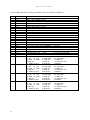
TABLE 2 RATE DATA
12
No.
ms/1000PPS
000
1000
001
800
002
600
003
500
004
400
005
300
006
200
007
150
008
125
009
100
010
75
011
50
012
30
013
20
014
15
015
10
016
7.5
017
5.0
018
4.0
019
2.0
020
1.5
021
1.0
4.Local mode driving
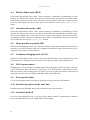
4. LOCAL mode driving
LOCAL mode driving is enabled when REMOTE button LED turn off. If its LED turns on, push the
button and turn it off.
4-1
Select motor speed
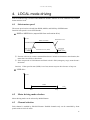
The motor speed can be selected from HSPD, MSPD, and LSPD by SPEED button.
Detail of each speed is set in SETUP mode.
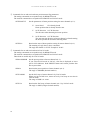
HSPD or MSPD drive (trapezoidal form acceleration drive)
Speed
HSPD or M SPD
Start Speed
Deceleration curve
End Speed
Acceleration curve (Rate)
LSPD
LSPD
Start
Time
Stop
※ If motor is driven by remote command that doesn’t include acceleration or deceleration, the
motor don’t accelerate or decelerate.
※ If the stop mode of STOP button and limit switch is EM (emergency stop), motor doesn’t
decelerate.
Caution) If the speed in start (LSPD) is too fast, motors may not drive because of step out.
LSPD drive
Speed
LSPD
Time
Start
4-2
Stop
Motor driving mode selection
Motor driving mode can be selected by MODE button.
4-3
Channel selection
Each channel is enabled by ENABLE button. Enabled channels only can be controlled by front
panel switch in LOCAL mode.
13
4.Local mode driving
4-4
Relative Index mode (REL)
RUN mode LED indicator shows “REL”. Pulse-out timing is controlled by START button. If some
channels are enabled, these motors starts driving at the same time automatically by START button.
Each channel’s pulse-out count is set at lower part in LCD indicator. Pulse-out is stopped by limit
switch or STOP button. The data at lower part in LCD indicator can be set by (+), (-), (←), (→)
button.
4-5
Absolute index mode (ABS)
RUN mode LED indicator shows “ABS”. Pulse-out timing is controlled by START button. If some
channels are enabled, these motors starts driving at the same time automatically by START button.
Each channel outputs pulse by the position at lower part in LCD indicator. Pulse-out direction is
decided automatically. Pulse-out is stopped by limit switch or STOP button. The data at lower part
in LCD indicator can be set by (+), (-), (←), (→) button.
4-6
Home position stop mode (HP)
RUN mode LED indicator shows “HP”. Pulse-out timing is controlled by START button. Pulse-out
direction is set in SETUP mode. Pulse-out is stopped when HP limit switch is detected. Pulse-out is
stopped by limit switch or STOP button too.
4-7
Continuous Stepping mode (SCAN)
RUN mode LED indicator shows “SCAN”. First, push START button. Next, push JOG lever to the
pulse-out direction, then pulse-out starts. Pulse-out is stopped by limit switch or STOP button.
4-8
JOG step movement
Pushing JOG lever is for inching of enabled channel. Throwing on this switch cause pulse-out to the
CW/CCW direction. Pulse-out count of a JOG step is set in SETUP mode. If throwing on it more
than 0.5 seconds or after reaching pulse-out count of a JOG step, pulse-out continues. Throwing off
stops pulse-out. JOG lever is available in HP, REL, ABS, and SCAN mode.
4-9
Preset position data
Can set current position data. Preset data is displayed at Lower part in the LCD indicator.
4-10 Start driving motors at the same time
Channels selected by ENABLE button can be started driving at the same time.
4-11 Automatic hold-off
In LOCAL and REMOTE mode, if you start driving hold-off motors, automatically the hold-off
mode is disabled and returns to be enabled after motor stopping.
14
4.Local mode driving
4-12 Hand-box control (Optional)
Hand Box is useful in LOCAL mode. Hand-box enables you to control motors seeing mechanical
movement. Control channel can be selected by rotary switch on the hand-box. A, B, C, D channels
can be controlled far from 3meter of PM4C-04. Preset speed is indicated in LED on the Hand Box.
Pushing JOG lever is for inching in enabled channel. Throwing on this switch cause pulse-out to the
CW/CCW direction. JOG pulse number is set in SETUP mode. This function is same as JOG lever
on the front panel of PM4C-06. If “ALWAYS” is set at hand-box page in SETUP mode, all channels
can be controlled by hand-box even if the cannels are disable in front panel. If “WHEN ENB” is set,
only enabled channels can be controlled.
15
5.Remote mode driving
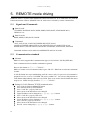
5. REMOTE mode driving
REMOTE mode is enabled when REMOTE button LED turns on. If its LED turns off, push the
button and turn the LED on. REMOTE/LOCAL mode can be selected by remote command too.
5-1
Signals and Commands
data for read
CHANNEL POSITION DATA, HSPD, MSPD, LSPD, RATE, STOP MODE & LS,
REM/LOC etc.
data for write
HSPD, MSPD, LSPD, RATE, LMSW
Command
+JOG, -JOG, SCAN, CONSTANT SPEED RELATIVE SCAN,
CONSTANT SPEED ABSOLUTE SCAN, RELATIVE SCAN, ABSOLUTE SCAN
SPEED SELECT, PAUSE ON/OFF, HOLD OFF SET/RESET, SLOW STOP, EM STOP
Commands for data-read is enable in both REMOTE and LOCAL mode.
5-2
Communication standard
Abstract
PM4C-06 series support three communication types, LAN, RS232C, GP-IB (IEEE-488).
Error command and un-executable command are ignored.
Receive data format is “□・・・・・・□CR+LF”.
PM4C-06 counts received command when it gets “CR+LF”. PM4C-06 executes the commands
in order.
In GP-IB, PM4C-06 stops handshaking until the correct reply for pre-received command is
prepared even if it is set as a TALKER. The wait is within 1ms. You can use SRQ function to
each channel independently when you use GP-IB. There is no need to check whether the motor
stops or not. PM4C-06 reply format is “□・・・・・・□CR+LF”
Setting for LAN (Ethernet TCP/IP) communication
Go to LOCAL mode by REMOTE button.
Go to SETUP mode by SETUP button.
Go to “LAN IP:1” page by JOG lever.
Move cursor to the data that is to be changed.
Upper IP address can be changed by (←), (→), (-), (+) button.
Go to “LAN IP:2” page by JOG lever.
Move cursor to the data that is to be changed.
Lower IP address can be changed by (←), (→), (-), (+) button.
Go to “Port no” page by JOG lever.
Move cursor to the data that is to be changed.
Port No. can be changed by (←), (→), (-), (+) button.
16
5.Remote mode driving
Default IP address is [192.168.1.55], and port number is [7777].
These data can be changed according to your network.
If you need to change port number, 10001 to 10999 are recommended.
You must power off and power on the unit to enable the new setting.
To confirm the new setting, you should try whether a command ("VER?" for example) is
received and the reply is sent out by the unit or not, by using client PC connected to PM4C-06
by telnet.
Setting for GP-IB communication
Go to LOCAL mode by REMOTE button.
Go to SETUP mode by SETUP switch.
Go to “GPIB ADD” page by JOG lever.
GP-IB address can be changed by using (-), (+) button.
After changing the address, push the "SETUP" button, then it has changed and the setting will
be finished. There is no need to power on again. You can check whether the communication is
OK or NOT by the command "VER?" for example.
Setting for RS232C communication
Go to LOCAL mode by REMOTE button.
Go to SETUP mode by SETUP switch.
Go to “232C BRT” page by JOG lever.
BAUD RATE can be changed by (-), (+) button.
After changing BAUD RATE, push the "SETUP" button, then the mode will be changed and
setting will be finished. There is no need to power on again. You can check whether the
communication is OK or NOT by the command "VER?" for example.
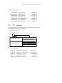
Pin assignment of the connector is as follows.
PM4C-06 side
Pin No.
RXD
TXD
GND
PC side
Connector of panel side : DE9P
Connector of cable side : DE9S
1
2
3
4
5
6
7
8
9
1
2
3
4
5
6
7
8
9
RXD
TXD
GND
The setting data for RS232C is only BAUD RATE data.
Another parameters of RS232C communication are fixed as follows.
DATA BIT : 8
STOP BIT : 1
NO FLOW CONTROL
NO PARITY
The delimiter for the data is “CR+LF”.
17
6.Command in detail (LAN, RS232C, GP-IB)
6. Command in detail (LAN, RS232C,
GP-IB)
The format of command is ASCII data, and the delimiter is “CR+LF” (0Dh + 0Ah). After receiving
“CR+LF”, command interpretation begins. When the unit receives the command without delimiter,
the receiving data will be considered to be front part characters of the command. If followed
commands are lost, command interpretation will be impossible. When sending commands,
"CR+LF" must be added at the end of the command. ("CR+LF" are omitted in the command
explained below.)
6-1
REMOTE/LOCAL command
These commands are acceptable in REMOTE and LOCAL mode.
These commands are acceptable when all channel motors are stopped.
LOC
Set into the LOCAL mode
REM
Set into the REMOTE mode
6-2
SRQ command (SRQ signal is one of GP-IB signal lines.)
These commands are acceptable in REMOTE and LOCAL mode
18
SRQx1
Set SRQ flag to channel x : x means motor channel 0~3.
When channel x motor stopped at this state, SRQ line of this unit goes "H" to
inform PC of the state and the SRQ status flag of this unit is set to "1".
Once SRQ status flag read out from PC, SRQ status flag is cleared
automatically and the SRQ line goes "L".
SRQ flag is cleared automatically just after SRQ line of this unit goes "H".
If you use SRQ signal when motor stopped, you have to set the flag every time
before start.
SRQx0
Clear the SRQ flag of channel x.
SRQ?x
Read out the status of SRQ flag of channel x.
The reply is "1" or "0".
6.Command in detail (LAN, RS232C, GP-IB)
6-3
Status read out command
These commands are acceptable in REMOTE and LOCAL mode.
STQ?
Read out the LOCAL/REMOTE mode and the number of stopped motors.
The reply is when REMOTE MODE : Rn (n:0~4)
when LOCAL MODE : Ln (n:0~4)
The maximum number of motors driving simultaneously is 4.
When the numbers of stopped motors is 0, there is no left motor to activate.
In this case, access command is ignored.
Before activating motors, you can check whether activated motor is left or not by
this command if you need.
STS?
Read out the LOCAL/REMOTE mode and the details of each motor state.
The format of reply data is like this.
R(L)abcd/PNNS/VVVV/HHJJKKLL/±uu・・・/±vv・・・/±ww・・・/±xx・・・
R or L
R: REMOTE mode
L: LOCAL mode
a,b,c,d
The selected motor channel number for each display channel 0~3.
PNNS
The state of motor action for each channel.
P : driving to CW direction
N : driving to CCW direction
S : stopped
VVVV
The states of limit switch and motor hold-off function for each
channel in hexadecimal.
< data bit >
b3: Motor hold off status
b2: The limit switch status of home position
b1: The limit switch status of CCW direction
b0: The limit switch status of CW direction
HHJJKKLL
This value shows the status of motor driving for each channel in
2digit hexadecimal data.
< data bit >
b7: ESEND received emergency stop command
b6: SSEND received deceleration stop command
b5: LSEND stopped by limit switch
b4: COMERR occurs error
b3: ACCN decelerating
b2: ACCPD accelerating
b1: DRIVE stepping
b0: BUSY data processing or stepping(= busy)
uu・・・,vv・・・,ww・・・,xx・・・
These are the latest pulse position data for each channel.
19
6.Command in detail (LAN, RS232C, GP-IB)
6-4
Motor control command
① JOG Command
This command is acceptable only for REMOTE mode.
JOGPx
Moves one pulse of motor channel x(0~3) to CW direction.
JOGNx
Moves one pulse of motor channel x(0~3) to CCW direction.
② Speed Select Command
These commands are acceptable only for REMOTE mode.
SPDHx
Motor speed selection of channel x(0~3) is "H"
SPDMx
Motor speed selection of channel x(0~3) is "M"
SPDLx
Motor speed selection of channel x(0~3) is "L"
Next command is acceptable for REMOTE and LOCAL mode.
SPD?x:
Read out the speed of channel x(0~3).
The replay is HSPD, MSPD or LSPD.
③ SCAN Command
These commands are acceptable only for REMOTE mode.
SCANPx
Continuous movement of motor channel x(0~3) to CW direction.
SCANNx
Continuous movement of motor channel x(0~3) to CCW direction.
The speed of the movement is determined by speed select command ②.
④ SCAN command set with absolute position data
This command is acceptable only for REMOTE mode.
ABSx±ddddddd
The motor of channel x(0~3) goes to the set position absolutely.
The range of ddd・・・・ is -8,388,607 ~ +8,388,607.
(Digit number is arbitrarily specified.)
⑤ SCAN command set by relative position data
This command is acceptable only for REMOTE mode.
RELx±ddddddd
The motor of channel x(0~3) moves at specified relative data.
The range of ddd・・・・ is -8,388,607 ~ +8,388,607.
(Digit number is arbitrarily specified.)
⑥ SLOW STOP, FAST STOP command
These commands are acceptable both in REMOTE and LOCAL mode.
20
SSTPx
Stop the driving motor channel x(0~3) with deceleration.
ESTPx
Stop the driving motor channel x(0~3) without deceleration.
6.Command in detail (LAN, RS232C, GP-IB)
ASSTP
Stop all the driving motors with deceleration.
AESTP
Stop all the driving motors without deceleration.
Another commands concerning motor moving
⑦ PAUSE ON/OFF command
These commands are acceptable only for REMOTE mode.
PAUSE ON
(S3016)
This command means the motion hold.
Once received this command, further commands are in suspended.
Those commands are in waiting state.
This suspended mode is released by the command "PASE OFF".
This command is useful when you activate some motors simultaneously.
This command doesn't affect any motor that is already moving.
PAUSE OFF
(S3017)
This command releases the suspended mode.
Motors that are in suspended mode by command "PASE ON" are
released.
Those motors start simultaneously after this command.
PAUSE?
Read out pause status.
reply: ON or OFF
⑧ HOLD ON/OFF command
These commands are acceptable only for REMOTE mode.
HOLDxON
Set Motor in channel x(0~3) hold on.
HOLDxOFF
Set Motor in channel x(0~3) hold off.
HOLD?x
Read out the state of hold on/off in channel x(0~3).
reply: ON or OFF
⑨ Constant speed SCAN command
These commands are acceptable only for REMOTE mode.
CSCANPx
Activate the motor channel x(0~3) to CW direction at constant speed.
CSCANNx
Activate the motor channel x(0~3) to CCW direction at constant speed.
SCANHPx
To detect the home position of motor channel x(0~3) along CW
direction.
When the home position is detected, motor stops suddenly.
So you need to move slowly to avoid step-out of motor.
When there is no home position, motor will be stopped at CW or CCW
limit switch.
If you know the home position roughly, you can check the home
position in a short time.
SCANHNx
This command is as same as "SCANHPx" without the direction CW.
The starting direction is CCW.
21
6.Command in detail (LAN, RS232C, GP-IB)
6-5
Command for set and read out parameters
① Commands for set and read out motor parameters
The setting commands are acceptable only for REMOTE mode.
The read out commands are acceptable for REMOTE and LOCAL mode.
SETMTxABCD
Set the fundamental characteristics of motor channel x(0~3)
A : 1/drive enable 0/drive disable
If you set the motor disable, you can't activate it and you can
avoid unexpected moving by the operation error.
Unless you set enable, you can't move the motor.
B : 1/hold on
0/hold off
When you set the motor hold off, this unit outputs the hold off
signal to external devices.
C : 1/trapezoidal (fixed)
The acceleration and deceleration mode of moving motor is fixed
to trapezoidal form.
D : 0/Pulse-Pulse 1/Pulse-Direction
Output signal to motor driver that is set outside of this unit is
selectable.
SETMT?x
This command is readout command above motor characteristics.
The reply data is in order ABCD. The default data is "1010".
STOPMDxAB
This command is set to stop motor channel x(0~3), slowly or fast.
A : 0/PB slow stop, 1/PB fast stop
It means slow stop or fast stop by STOP switch on front panel.
B : 0/LS slow stop, 1/LS fast stop
It means slow stop or fast stop by limit switch.
STOPMD?x
This command is readout command above motor stop way.
The reply data is in order AB. The default data is "00".
② Commands for set and read out speed parameters
The setting commands are acceptable only for REMOTE mode.
The read out commands are acceptable for REMOTE and LOCAL mode.
22
SPDHxdddd・・・
The high speed of motor channel x(0~3) is dddd・・・. Unit is PPS.
SPDH?x
This command is readout command above SPDHx.
The reply is dddd・・・. Unit is PPS.
SPDMxdddd・・・
The middle speed of motor channel x(0~3) is dddd・・・. Unit is PPS.
SPDM?x
This command is readout command above SPDMx.
The reply is dddd・・・. Unit is PPS.
6.Command in detail (LAN, RS232C, GP-IB)
SPDLxdddd・・・
The low speed of motor channel x(0~3) is dddd・・・・. Unit is PPS.
SPDL?x
This command is readout command above SPDLx(0~3).
The reply is dddd・・・. Unit is PPS.
③ Commands for set and read out acceralaton and deceleration parameters
The setting commands are acceptable only for REMOTE mode.
The read out commands are acceptable for REMOTE and LOCAL mode.
RTExddd
The acceleration and deceleration of motor channel x(0~3) is set by this
command.
ddd: 0~021
This is a code number. See TABLE 2 RATE DATA.
RTE?x
This command is for reading the acceleration and deceleration value of
motor channel x(0~3). The reply is ddd.
④ Commands for set and read out latest pulse position parameters
The setting commands are acceptable only for REMOTE mode.
The read out commands are acceptable for REMOTE and LOCAL mode.
PSx±dddddd
Set the current position data of motor channel x(0~3).
The range of dddd・・・・・ is -8,388,607 ~ +8,388,607.
(The number of digit is arbitrary.)
PS?x
Read out the current data of motor channel x(0~3).
The reply is ±ddddddd (decimal number).
⑤ Commands for set and read out digital limit position parameters
The setting commands are acceptable only for REMOTE mode.
The read out commands are acceptable for REMOTE and LOCAL mode.
FLx±ddddddd
Set the digital limit data to CW side of motor channel x(0~3).
When you set the digital limit switch available, the motor doesn't move
over the preset position.
(When limit switch stop mode is deceleration stop mode, motor overrun
at some range.)
If you set digital limit switch available and present position is out of
moving area, motor could move to the moving area direction.
FL?x
Read out the digital limit data to CW side of motor channel x(0~3).
The reply is ±ddddddd (decimal number).
BLx±ddddddd
Set the digital limit data to CCW side of motor channel x(0~3).
When you set the digital limit switch available, the motor doesn't move
over the preset position.
(When limit switch stop mode is deceleration stop mode, motor overrun
at some range.)
If you set digital limit switch available and present position is out of
moving area, motor could move to the moving area direction.
BL?x
Read out the digital limit data to CCW side of motor channel x(0~3).
The reply is ±ddddddd (decimal number).
23
6.Command in detail (LAN, RS232C, GP-IB)
⑥ Commands for set and read out home position status flag parameters
The setting commands are acceptable only for REMOTE mode.
The read out commands are acceptable for REMOTE and LOCAL mode.
SETHPx0XYZ
Set the parameters of home position setting for motor channel x(0~3).
X : 0/not found
1/LS already found
Home position data is already found or not.
Y : 0/CW direction 1/CCW direction
The direction when detecting the home position
Z : 0/CW direction 1/CCW direction
The start moving direction of motor channel x when detecting
the home position in automatic detecting mode
SETHP?x
Read out the state of home position setting for motor channel x(0~3).
The meaning of reply data is above command.
The reply data format is :0XYZ. Example is "0100".
⑦ Commands for set and read out data in LOCAL mode
The setting commands are acceptable only for REMOTE mode.
The read out commands are acceptable for REMOTE and LOCAL mode.
These data are useful only for LOCAL mode.
24
SPRSx±ddddddd
Set the preset position of motor channel x(0~3).
If you select SCAN mode in LOCAL, sent data is displayed at lower
part in LCD indicator. Push PRESET button and current position data
turn to preset data.
SPRS?x
Read out the preset position of motor channel x(0~3).
The reply is ±ddddddd (decimal number).
SETJGxdddd
Set the JOG steps of motor channel x by LOCAL mode.
When you put on JOG lever, motor moves by JOG steps at one time in
LOCAL mode.
The range of dddd is 0 ~9999.
SETJG?x
Read out the JOG steps of motor channel x(0~3) by LOCAL mode.
The reply is ±dddd (4 digits decimal number).
6.Command in detail (LAN, RS232C, GP-IB)
6-6
Command for set and read out limit switch data parameters
The setting commands are acceptable only for REMOTE mode.
The read out commands are acceptable for REMOTE and LOCAL mode.
SETLSxDYYY0yyy
Set the states of limit switch of motor channel x(0~3).
D
: 0/Digital limit switch disable, 1/Enable
YYY : 0/Limit switch disable, 1/Enable
(State of CW and CCW LS become same state of
HP LS. All LS become enabled only or disable only.)
yyy
: 0/Limit switch set is N.O, 1/N.C
(State of CW LS becomes same state of CW LS.
Their contact has to be same type.)
YYY,yyy The order is H.P LS, CCW LS, CW LS.
SETLS?x
Read out the states of limit switch of motor channel x(0~3).
The reply is DYYY0yyy. (Meaning is shown above.)
LS?
Read out the motor channel and the states of limit switch for channels.
The reply data is abcdHJKL.
a,b,c,d
: It means the motor channel for A,B,C,D channel.
It's a hexadecimal number.(One character)
H,J,K,L : It means the state of limit switch for channels.
b3 (hold off)
1:holdoff
0:hold on
HDSTLS?
b2 (HP LS)
1:LS on
0: LS off
b1 (CCW LS)
1:LS on
0: LS off
b0 (CW LS)
1:LS on
0: LS off
Read out the state of hardware and software limit switch for channels.
The reply data is abcdHHHHSSSS.
a,b,c,d
: It means the motor channel for A,B,C,D channel.
It's a hexadecimal number.(One character)
H,H,H,H : state of hardware limit switch for A,B,C,D channel.
S,S,S,S
: state of software limit switch for A,B,C,D channel.
b3
b2 (HP LS)
b1 (CCW LS)
0
1:LS on
1:LS on
0
0: LS off
0: LS off
※ HP LS is hardware limit switch only.
b0 (CW LS)
1:LS on
0: LS off
25
6.Command in detail (LAN, RS232C, GP-IB)
6-7
Others
VER?
Read out version information of inside firmware program.
The reply will be like "1.00 10-10-01 PM4C-06" in PM4C-06.
The same firmware is installed to PM4C-06 series.
VERH?
For maintenance
Read out the hardware version of this unit.
FROM0,FROM1
For maintenance
You can select the active flash ROM.
NOTICE : When you use this command and power on this unit or send
command "REST", program starts again by specified ROM
and all parameters are initialized.
26
FROM?
For maintenance
There are two flash ROM for program memory inside.
You can check which one is active for flash ROM.
The reply is FROM0/FROM1.
REST
For maintenance
Can restart the program without power switch operation
STEM?
For maintenance
Can be read out status port 1 of inner IC MCC05.
Reply is aaaa/bbbb/cccc/dddd.
The status of control IC A,B,C,D are read out in hexadecimal style.
7.Firmware version up
7. Firmware version up
You can perform firmware upgrade of PM4C-06 series via communication line. To keep safety you
had better cut off the connection from unit to motor driver, or put off the power line of motor drivers.
It's convenient to use RS232C or LAN connection.
We have firmware-upgrading program for Windows.
http://www.tsuji-denshi.co.jp/download_file/lan_rs_file_send.EXE
http://www.tsuji-denshi.co.jp/manual_pdf/pm16c_04xd_vup_soft.pdf
The procedures of upgrade via LAN communication using "Tera Term" free software
① Download the text-file for version upgrade from TSUJI-ELECTRIC HP, and unzip it to your
PC.
② Launch the program "Tera Term".
Select TCP/IP and enter IP address and port No of PM4C-06.
Operation is SETUP -> Terminal then setting of New-Line is to be CR+LF in Receive and
Transmit set.
Mark on Local echo and "OK". Send the command VER? , and reply is like
"1.00 10-10-01 PM4C-06" then the connection will be good.
③ Set PM4C-06 to REMOTE mode by local operation or remote operation.
To change in remote operation sends the command "REM".
④ Operation is File -> Send file then click the file name.
Specify the file name and "OPEN".
It begins the download procedure.
⑤ You can see the process of transferring the file data to PM4C-06 on your PC.
The "REMOTE" lamp on the PM4C-06 is blinking on and off slowly that indicates receiving
the file by PM4C-06.
⑥ For about 90 seconds download procedures continues, then "REMOTE" lamp turns on quick
blinking mode. Then the data write procedure begins to start for about 20 seconds.
After finishing data write procedure to flash ROM, "REMOTE" lamp turns off.
Program upgrade procedure is finished
⑦ Set TCP/IP line off, and then finish the TeraTerm program.
Put off the power line of PM4C-06, and then put on this unit again.
If you don't want to put off the unit, send command "REST".
Thus the unit runs again from new version program.
If trouble occurred in download process, when put on the unit again, sometimes program runs out of
control. In this case once put off the unit and put on it again pushing STOP button and SPEED
button. The unit runs from previous ROM version again. And you can try again upgrading
procedure.
Even if by the above operation, program runs out of control you can start again next procedure.
There is a communication program in CPU-ROM.
27
7.Firmware version up
When you use this mode you have to pay attention to following procedures.
CAUTION: When you open the cover of this unit, be careful to get shock.
First take out power cable of it.
If you have some troubles to do next procedure please contact us.
1. Put off the power switch of this unit and opens the top cover.
Set the DIPswitch 1 to side "ON". (DIPswitch 2 is still side "OFF".)
DIPswitch is beside connector 9 on print circuit board "TEP178"
2. Put on the power line pushing STOP and MODE button.
The "RED" led lamp that indicate "REMOTE" is flashing on and off for 15 seconds, then "RED"
lamp turn on red continuously.
At this stage LCD display is not correct yet.
3. Put off the power switch of this unit again, then set the DIPswitch 1 to side "OFF".
(DIPswitch 2 is still side "OFF".)
4. Put on the power line pushing REMOTE button.
Program starts by Version 1.00 firmware.
(In this stage if LCD display may not be correct, but don't care of it. It's OK if you can change
remote-local mode by REMOTE button.)
Next procedure is above described ①~⑦.
When you change firmware program all preset data are cleared, and setting data will become default
state.
28
8.Old command in detail (for LAN, RS232C, GP-IB)
8. Old command in detail (for LAN,
RS232C, GP-IB)
Commands are available in ASCII code only.
De-limiter is fixed to be “CR+LF” both in send data and receive data.
8-1
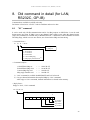
"S1" command
It can be used only GP-IB communication and is for SRQ request on GP-IB line. It can be used
during motor stop state. If SRQ is set to one channel, SRQ signal occurs when the channel motor
stops. This command is available only in REMOTE mode.1) Send form of the commands are below.
The SRQ flags, which were set once before, are cleared at the SRQ send out timing.
< Command form >
S1 ○ △
CR+LF
0 : A Position
1 : B Position
2 : C Position
3 : D Position
8 : current SRQ flag
9 : SRQ reply channel read 2)
0 : SRQ clear
1 : SRQ set
< Command sample >
A POSITION SRQ set
B POSITION SRQ clear
Current SRQ flag read
SRQ reply channel read
・・・
・・・
・・・
・・・
S101CR+LF
S110CR+LF
S18CR+LF
S19CR+LF
1) "S18" command is available both REMOTE and LOCAL mode.
2) Can get channel information that replied SRQ by "S19" command.
After reply to "S19" command, channel information is cleared in the memory.
< Reply form>
Reply to "S18", "S19" command
R0 □ CR+LF
total value of bit 1~4 in hex
7
0
0
0
0
0
A position
B positon
C position
D position
29
8.Old command in detail (for LAN, RS232C, GP-IB)
8-2
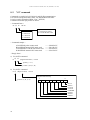
"S2" command
Commands are useful in LAN, RS232C and GP-IB communication.
It is used to read position data, status, LS, HP and Hold-off status.
It can be used in all modes (REM / LOC / SETUP).
Command form and reply forms are below.
< Command form >
S2 ○ △
CR+LF
0 : A Position
1 : B Position
2 : C Position
3 : D Position
0 : pulse count data
1 : internal CPU status
2 : LS・ HP・ H.OFF status
< Command sample >
A POSITION pulse counter read
B POSITION internal CPU status read
C POSITION LS・HP・H.OFF status read
D POSITION internal CPU status read
・・・
・・・
・・・
・・・
S200CR+LF
S211CR+LF
S222CR+LF
S231CR+LF
<Reply form>
a) For S2※0 command
R ○ △ (7d igit decimal data) CR+LF
polarity (+ o r -)
position (A, B, C, D)
b) For S2※1 command
R ○ (2d igit hex data) CR+LF
2digit hex data bit map
position (A, B, C, D)
7
0
BUSY
DRIVE
not used
not used
COM ERR
LSEND
SSEND
ESEND
30
8.Old command in detail (for LAN, RS232C, GP-IB)
bit information
BUSY
DRIVE
COMERR
LSEND
SSEND
ESEND
: internal CPU is busy. Any command are receivable when bit=0 1)
: internal CPU is now on pulse out status.
: command is not regal 2)
: PULSE was stopped by limit switch. 2,3)
: PULSE was stopped by slow stop command. 2,3)
: PULSE was stopped by EM command. 2,3)
1) Only SLOW STOP, EM STOP command are available in BUSY=1,DRIVE=1 (on driving)
state.
2) COMERR, LSEND, SSEND, ESEND BIT are valid in BUSY=0 status.
These bit are cleared by next command.
3) LSEND, SSEND, ESEND BIT are valid only after end of driving.
c) For S2※2 command
R ○ (1d igit hex data) CR+LF
1digit hex data bit map
position (A, B, C, D)
3
0
CW LS status ( 0:Non active 1:Active )
CCW LS status ( 0:Non active 1:Active )
HP LS status ( 0:Non active 1:Active )
H.OFF status ( 0:H.ON
1:H.OFF )
31
8.Old command in detail (for LAN, RS232C, GP-IB)
8-3
"S3" command
Commands are useful in LAN, RS232C and GP-IB communication.
"S3" command is used to pulse out or pulse stop and set condition data.
If the channel is scanning (BUSY BIT=1) these commands are ignored except pulse stop command.
< Command form type 1 >
S3 ○ (2d igit HEX data) CR+LF
0 : A Position
1 : B Position
2 : C Position
3 : D Position
08, 0A : +JOG (1pulse)
09, 0B : -JOG (1pulse)
0C
: +SCAN (no acc.)
0D
: -SCAN (no acc.)
0E
: +SCA N (with acc.)
0F
: -SCA N (with acc.)
16
: PAUSE ON 1)
17
: PAUSE OFF 1)
18
: HOLD OFF set
19
: HOLD OFF clear
1E
: HP STOP +SCAN (with acc.)
1F
: HP STOP +SCAN (with acc.)
40
: SLOW STOP
80
: EM STOP
1) PAUSE ON/OFF command controls one circuit line on the board,
any position mark (A, B, C, D) will work as the same command.
< Command Sample >
A POSITION
B POSITION
C POSITION
D POSITION
+JOG command
HOLD OFF set
+SCAN command
slow stop command
・・・
・・・
・・・
・・・
S3008CR+LF(or S300ACR+LF)
S3118CR+LF
S320ECR+LF
S3340CR+LF
< Command form type 2 >
S38 ○ (±7d igit decimal data) (2d igit HEX data) CR+LF
0 : A Position
1 : B Position
2 : C Position
3 : D Position
±8388607
(0 ~ FFFFFF in HEX)
10 : INDEX SCAN (no acc.)
11 : ABSOLUTE SCAN (no acc.)
12 : INDEX SCAN (with acc.)
13 : ABSOLUTE SCAN (with acc.)
< Command sample >
A POSITION +1234567 INDEX SCAN(no acc.)
B POSITION -0200000 ABSOLUTE SCAN(no acc.)
C POSITION +0000000 INDEX SCAN(with acc.)
D POSITION -0000100 ABSOLUTE SCAN(with acc.)
32
・・・S380+123456710CR+LF
・・・S381-020000011CR+LF
・・・S382+000000012CR+LF
・・・S383-000010013CR+LF
8.Old command in detail (for LAN, RS232C, GP-IB)
< Command form type 3 >
S39 ○ △ <const.1> CR+LF
0 : A Position
1 : B Position
2 : C Position
3 : D Position
0 : HSPD change
3digit (000 ~ 187) 2)
1 : MSPD change
3digit (000 ~ 187) 2)
2 : LSPD change
3digit (000 ~ 161) 2)
3 : RATE change
2digit (00 ~ 18) 3)
4 : JOG pulse set
4digit (0000 ~ 9999) 4)
5 : LS STOP MODE set
1digit (0:SLOW STOP / 1:EM STOP)
6 : PB STOP M ODE set
1digit (0:EM STOP / 2:SLOW STOP)
7 : H.OFF set/clear
1digit (0:clear / 4:set)
8 : HP SCAN DIR set
1digit (0:CCW / 8:CW)
9 : couter preset
±7dig it decimal (max ±8388607)
2) It must be 3 digit data
3) It must be 2 digit data
4) It must be 4 digit data
Caution) Speed data change by this "S39" needs "S71" command to effective new data.
"S71" command is the sign to start changing speed data.
< Command sample >
A POSITION
B POSITION
C POSITION
D POSITION
A POSITION
B POSITION
C POSITION
D POSITION
A POSITION
B POSITION
C POSITION
D POSITION
A POSITION
HSPD set to 100
MSPD set to 15
LSPD set to 5
RATE set to 10
JOG pulse set to 1234
LS STOP set to slow stop
LS STOP set to EM stop
PB STOP set to slow stop
H.OFF clear
H.OFF set
HP SCAN DIR set to CCW
HP SCAN DIR set to CW
counter preset +1234567
・・・
・・・
・・・
・・・
・・・
・・・
・・・
・・・
・・・
・・・
・・・
・・・
・・・
S3900100CR+LF
S3911015CR+LF
S3922005CR+LF
S393310CR+LF
S39041234CR+LF
S39150CR+LF
S39251CR+LF
S39362CR+LF
S39070CR+LF
S39174CR+LF
S39280CR+LF
S39399CR+LF
S3909+1234567CR+LF
33
8.Old command in detail (for LAN, RS232C, GP-IB)
8-4
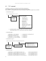
"S4" command
Commands are useful in LAN, RS232C and GP-IB communication.
"S4" command is mainly used to read setting data for each channel.
It can be used at any time whether pulse control CPU is busy or not, REMOTE or LOCAL mode.
< Command form >
S4 ○ △ CR+LF
0 : A Position
1 : B Position
2 : C Position
3 : D Position
8 : status of panel
0 : HSPD data read
1 : MSPD data read
2 : LSPD data read
3 : RATE data read
4 : JOG pulse data read
5 : status data read
< Receive data form >
a) POSITION data read
R ○ □ <const.2> CR+LF
4digit decimal data
0 : A Position
1 : B Position
2 : C Position
3 : D Position
H : HSPD data read
M : MSPD data read
L : LSPD data read
R : RATE data read
JP: JOG pulse data read
S : status data read
b) Status information for the panel
R ○ □ <const.3> <const.4> CR+LF
2digit HEX code bit map
C : SETUP mode
N : NORMAL mode
7
0
0
ABS mode
REL mode
H.P mode
SCAN mode
SPEED Low
SPEED M id
SPEED Hi
L : LOCAL mode
R : REM OTE mode
2digit decimal data bit map
7
0
0
0
0
0
A POS.
B POS.
C.POS.
D POS.
34
8.Old command in detail (for LAN, RS232C, GP-IB)
< Command sample >
A POSITION HSPD data read
B POSITION MSPD data read
C POSITION LSPD data read
D POSITION RATE data read
A POSITION JOG pulse data read
D POSITION status data read
status information for the panel
8-5
・・・
・・・
・・・
・・・
・・・
・・・
・・・
S400CR+LF
S411CR+LF
S422CR+LF
S433CR+LF
S404CR+LF
S435CR+LF
S48CR+LF
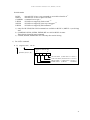
"S7" command
Commands are useful in LAN, RS232C and GP-IB communication.
It is used to change status of the panel.
< Command form >
S7 ○ △ CR+LF
0 : REM/ LOC change
R : REM OTE mode change
L : LOCAL mode change
H : Speed Hi change
1 : SPEED change
M : Speed Mid change
L : Speed Low change
< Command sample >
PM4C-06
PM4C-06
PM4C-06
PM4C-06
PM4C-06
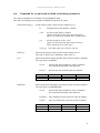
REMOTE mode change ・・・ S70RCR+LF
LOCAL mode change ・・・ S70LCR+LF
SPEED Hi change
・・・ S71HCR+LF
SPEED Mid change
・・・ S71MCR+LF
SPEED Low change
・・・ S71LCR+LF
35
9.Hand Box control (Optional)
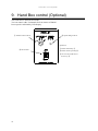
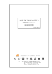
9. Hand Box control (Optional)
This controller is useful in local mode.
You can control A,B,C,D channels far from 3meter of PM16C.
Preset speed is indicated by LED display.
① channel select switch
② speed change switch
Operation
① Select channel by ①
③ JOG switch
② Select motor speed by ②
③ Access CW,CCW motor
access by ③
36
10.Data initialization
11.Additional function
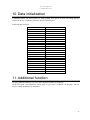
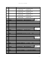
10. Data initialization
If PRESET button and STOP button are being pushed when power on reset, all setting data are
initialized. In case of updating firmware, they are initialized too.
Initialized data are below.
Item
HSPD
MSPD
LSPD
RATE
Current position
Preset data
JOG PULSE
LS
LS CONTACT
LS STOP
PB STOP
HOLD OFF
HP.START
HP CONTACT
PULES MODE
DIGITAL LS
DIGITAL CWLS
DIGITAL CCWLS
RS232C
GPIB ADD
IP ADD
PORT No.
HAND BOX
Default
048(3700PPS)
016(650PPS)
001(10PPS)
005(300ms)
0
0
1
ENABLE
N.C
FAST
SLOW
ENABLE
CW
N.O
P-P MODE
DISABLE
1000000
-1000000
38400 BAUD
07
192.168.1.55
7777
WHEN ENB
11. Additional function
By using additional function, you can control disabled channel by Hand Box.
At SETUP mode, open Hand Box setting page. If you select “ALWAYS” in the page, you can
always control all channels by Hand Box.
37
12.Connection with outer equipment
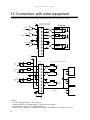
12. Connection with outer equipment
Connection cables are recommended to be shielded twist pair cable. (more than 0.2mm2)
+5V
CWP
connector PIN assign
DE9S(TO DRIVER)
DRIVER
1
(PULSE)
2
CCWP
300Ω
3
(DIRECTION)
4
300Ω
5
H.OFF
6
7
300Ω
8
9
0V
+12V
CW
LS
1kΩ
DE9P
(TOLS)
LS type : both N.O and N.C ok
1
CW
LS
2
CCW
LS
1kΩ
12V
1P
3
CCW
LS
4
2P
5
ZERO
LS
1kΩ
0V
12V
6
ZERO
(HP) LS
7
3P
SIG
4P
0V
8
9
SIG
12V total
0.5A max
12V
6P
SIG
7P
0V
PM4C
Caution)
N.G (the origin proximity) is not used now.
Connector shell size of DE9P and 9S is varied from each maker's.
Outward form <35W can be used for PM4C-06.
DE-C1-J6(JAE), XM2S-0911(OMRON) and HDE-CTF(HIROSE) are possible to be used.
38
13.Performance and specifications
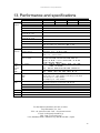
13. Performance and specifications
Input/
Output
LCD
display
PRODUCT
Control motor
Capability
Output
Pulse rate
Pulse control number
Acceleration and
Deceleration rate
Acceleration and
Deceleration form
Output format
Pulse out connector
Limit switch input
Limit switch connector
Characters and lines of
Display device
Display default
Display contents in
Data set mode
Panel
push
button
and
lamp
Control
All channel
Each channel
PMCD-06N, X
PM2C-06
PM3C-06
PM4C-06
1
2
3
4
1
2
3
4
CW, CCW, HOLD OFF (5V,8mA:line driven) for each motor driver
5 ~ 100,000PPS(LOC) / 1 ~ 100,000PPS(REM)
0 ~ ±8,388,607
1000ms ~ 1.0 ms/KHz
Constant speed, trapezoidal form
2pulse / 1pulse
DE9S (F)
CW-LS, CCW-LS, HOME-LS 12V 5mA (minus common) and power supply
+12v for censer for each motor (Max. 0.5A).
DE9P (M)
8characters × 2lines
(character size : 11.4H × 6.1W)
Upper line : current position
Lower line : preset value
HSPD, MSPD, LSPD, RATE, JOG PULSE, LS EN/DA, LS NO/NC,
LS STOP FAST/SLOW, PB STOP FAST/SLOW, HOLD OFF,
HP DIR, HP NO/NC, P-P/P-D, RS232C BAUD, GP-IB ADD,
IP ADD, MAC ADD, HAND BOX
Button : REM/LOC, SETUP, PRESET, START, STOP, MODE,
SPEED, JOG CW/CCW
Lamp : REM/LOC, MODE/HP-REL-ABS-SCAN, SPEED/H-M-L
Button : UP, DOWN, INC, DEC, ENABLE
Lamp : ENABLE, CWLS, CWP, CCWP, CCWLS, MF, HP
preset specified data to the ready channel
moving start for ready channel according to the mode
stop moving for ready channel
jog stepping for ready channel
continuous stepping operation of ready channel.
Stepping direction is according JOG switch.
moving to specified position of ready channel
moving specified steps of ready channel
stop by Home Position Limit Switch
PRESET
START
STOP
JOG
Stepping SCAN MODE
mode
ABS IDX MODE
REL IDX MODE
HP STOP MODE
Remote
LAN, GP-IB, RS232C
Case
EIA 2 UNIT rack mount type (88H×482W×325D)
Power
AC 85V ~ 264V 47 - 440Hz 50VA
For the further information, feel free to ask us.
Tsuji-Electronics Co., Ltd
TEL: +81-(0)29-832-3031 FAX: +81-(0)29-832-2662
E-mail : [email protected]
URL : http://www.tsujicon.jp
3739, Kandatsu-machi, Tsuchiura-city, Ibaraki 300-0013, Japan
39
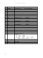
PM4C-06 series command list
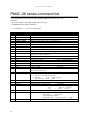
PM4C-06 series command list
Below commands are not only for 4ch controller (PM4C) but also for 1ch~3ch
controller.
・for LAN,RS232C,GP-IB (delimiter:CR+LF(fixed))
・COMPATIBLE TO PM16C-04XD(L)
x : 0~3(channel)
MODE
R
R
R
R/L
R
R
R/L
R
R
R/L
R
R
COMMAND
ABSx±ddddddd
ASSTP, AESTP
BLx±ddddddd
BL?x
CSCANPx,CSCANNx
FLx±ddddddd
FL?x
JOGPx, JOGNx
LOC
LS?
PAUSE ON
PAUSE OFF
R
R
R/L
R
L
R
R/L
R
PAUSE?
PSx±ddddddd
PS?x
RELx±ddddddd
REM
RTExddd
RTE?x
SCANHPx,SCANHNx
R
R
SCANPx,SCANNx
SETHPx0XYZ
R/L
R
R/L
R
SETHP?x
SETJGxdddd
SETJG?x
SETLSxDYYY0yyy
R/L
R
SETLS?x
SETMTxABCD
R/L
SETMT?x
40
dd・・・d : decimal data
NOTE
absolute index scan
all moving motor slow stop or fast stop
set backward digital limit
read backward digital limit
reply:±ddddddd(decimal)
constant speed scan to cw or ccw direction
set forward digital limit position
read forward digital limit
reply:±ddddddd(decimal)
Jog command (one step to cw or ccw direction)
LOCAL mode change
LS read
reply:abcdHJKL
set pause. send before scan start command.
clear pause. send after scan start command for synchronous
scan start of multi channels
read out / reply: ON or OFF
preset position data
read position data
reply:±ddddddd(decimal)
relative index scan
REMOTE mode change
acc. rate set
ddd:0~021(see RATE TABLE p9 )
read acc. RATE
reply:ddd
accelerative scan to cw or ccw direction
if HP switch then stop
accelerative scan to cw or ccw direction
HP find information set
X: found/1, not found/0(reserved)
Y: found dir.
0/cw, 1/ccw(reserved)
Z: auto start dir. 0/cw, 1/ccw
read HP find information reply:0XYZ
set Jog pulse for manual PB
read JOG pulse for manual PB
reply:DDDD
set LS characteristics
D:digital limit enable/1, disable/0
Y:LS
enable/1, disable/0
y:LS
N.C/1,
N.O/0
read LS setting
reply:DYYY0yyy(see SETLSx)
motor drive set
A:1/drive enable 0/disable
B:1/hold on
0/hold off
C:1/trapezoidal(fixed)
D:0/Pulse-Pulse
1/Pulse-Direction
2/PDR
read motor set
reply:ABCD
PM4C-06 series command list
MODE
R
R/L
R
R/L
R
R/L
R
R/L
R
R/L
R/L
R
R
COMMAND
SPDHx,SPDMx,SPDLx
SPD?x
SPDHxdddd・・・
SPDH?x
SPDLxdddd・・・
SPDL?x
SPDMxdddd・・・
SPDM?x
SPRSx±ddddddd
SPRS?x
SRQx1
(ONLY FOR GP-IB)
SRQx0
(ONLY FOR GP-IB)
SRQ?x
(ONLY FOR GP-IB)
SSTPx,ESTPx
STOPMDxAB
R/L
R/L
STOPMDx?
STQ?
R/L
STS?
R/L
HDSTLS?
R/L
HOLD?x
R
R
HOLDxON
HOLDxOFF
R/L
R/L
NOTE
change speed(can set 0~3ch individually)
read speed
reply:HSPD or MSPD or LSPD
set HSPD to ddd・・・ in pps unit(1~100,000)
read HSPD
reply:dddddd
set LSPD to ddd・・・ in pps unit(1~100,000)
read LSPD
reply:dddddd
set MSPD to ddd・・・ in pps unit(1~100,000)
read MSPD
reply:dddddd
set preset data for LOCAL mode
read preset data for LOCAL mode
reply:±DDD・・・DD
SRQ flag set
auto reset after SRQ out
SRQ flag reset
SRQ flag read
reply:1 or 0
slow stop or fast stop
set PB and LS stop mde
A:0/LS slow stop 1/LS fast stop
B:0/PB slow stop 1/PB fast stop
read PB & LS stop mode
reply:AB
A,B:0,1
REMOTE/LOCAL mode and moving motor information
reply: Rn or Ln n:0 ~ 4 stopping motor number
(if n = 0 then you can't start another motor)
Status read out
reply:
R(L)abcd/PNNS/VVVV/HHJJKKLL/±uu・・・/±vv・・・/±ww・・・/±xx・・・
PNNS:P:cw moving N:ccw moving S:stopped
VVVV:LS status & hold off status
HH,JJ,KK,LL:mcc status
uu・・・,vv・・・,ww・・・,xx・・・ :current position
hard and soft limit sw read
reply:abcdHHHHSSSS abcd/ch, HHHH/hard SSSS/soft
hold on/off state read x:ch(0,1,・・・9,A,B,C,D,E,F)
reply: ON or OFF
hold on set to ch x
hold off set to ch x
FOR MAINTENANCE
R/L
R/L
R
R/L
R/L
R/L
FROM0, FROM1
FROM?
REST
STSM?
VER?
VERH?
FROM select
current FROM read reply:FROM0,FROM1
restart without power off-on
read status port1 of MCC06 aaaa/bbbb/cccc/dddd
read version reply: 1.00 10-10-01 PM4C-06
hardware version read reply:HD-VER0,1,2,5,6
41
PM4C-06 series command list
OLD COMMAND LIST(Existing commands below are available to PM4C-06.)
MODE
R
R
R
R
R
R
R
R
R/L
R
R/L
R/L
R/L
R/L
R/L
R/L
R/L
R/L
R/L
R/L
R/L
R/L
R
COMMAND
S100
S101
S110
S111
S120
S121
S130
S131
S18
S19
S200
S201
S201
S210
S211
S212
S220
S221
S222
S230
S231
S232
S30□□
R
S31□□
R
S32□□
R
S33□□
42
NOTE
cancel A CH SRQ
GP-IB only
SRQ set when A MOTOR stopped
〃
cancel B CH SRQ
〃
SRQ set when B motor stopped
〃
cancel C CH S
〃
SRQ set when C motor stopped
〃
cancel D CH SRQ
〃
SRQ set when D motor stopped
〃
SRQ flag read
R0□ □:1/A POS., 2/B POS. 3/A,B POS. ・・・
SRQ out CH read
R0□ □:1/A POS., 2/B POS. 3/A,B POS. ・・・
A CH position data read RA±DDDDDDD
D:decimal
A CH CPU status read
RAHH
H:hex code, b0 BIT:BUSY
A CH LS, HP, HOLD OFF status read
0:CWLS, b1:CCWLS, b2:HP, b3:H.OFF
B CH position data read RB±DDDDDDD
D:decimal
B CH CPU status read
RBHH
H:hex code, b0 BIT:BUSY
B CH LS, HP, HOLD OFF status read
0:CWLS, b1:CCWLS, b2:HP, b3:H.OFF
C CH position data read RC±DDDDDDD
D:decimal
C CH CPU status read
RCHH
H:hex code, b0 BIT:BUSY
C CH LS, HP, HOLD OFF status read
0:CWLS, b1:CCWLS, b2:HP, b3:H.OFF
D CH position data read RD±DDDDDDD
D:decimal
D CH CPU status read
RDHH
H:hex code, b0 BIT:BUSY
D CH LS, HP, HOLD OFF status read
0:CWLS, b1:CCWLS, b2:HP, b3:H.OFF
A POSITION 2 BYTE COMMAND
□□:COMMAND
08:+JOG
09:-JOG
0C:+CSPD SCAN
0D:-CSPD SCAN
0E:+SCAN
0F:-SCAN
16:PAUSE ON
17:PAUSE OFF
18:HOLD OFF
19:HOLD ON
1E:+SCAN & HP STOP
1F:-SCAN & HP STOP
40:SLOW STOP
80:EM.STOP
B POSITION 2 BYTE COMMAND
□□:COMMAND
08:+JOG
09:-JOG
0C:+CSPD SCAN
0D:-CSPD SCAN
0E:+SCAN
0F:-SCAN
16:PAUSE ON
17:PAUSE OFF
18:HOLD OFF
19:HOLD ON
1E:+SCAN & HP STOP
1F:-SCAN & HP STOP
40:SLOW STOP
80:EM.STOP
C POSITION 2 BYTE COMMAND
□□:COMMAND
08:+JOG
09:-JOG
0C:+CSPD SCAN
0D:-CSPD SCAN
0E:+SCAN
0F:-SCAN
16:PAUSE ON
17:PAUSE OFF
18:HOLD OFF
19:HOLD ON
1E:+SCAN & HP STOP
1F:-SCAN & HP STOP
40:SLOW STOP
80:EM.STOP
D POSITION 2 BYTE COMMAND
□□:COMMAND
08:+JOG
09:-JOG
0C:+CSPD SCAN
0D:-CSPD SCAN
0E:+SCAN
0F:-SCAN
16:PAUSE ON
17:PAUSE OFF
18:HOLD OFF
19:HOLD ON
1E:+SCAN & HP STOP
1F:-SCAN & HP STOP
40:SLOW STOP
80:EM.STOP
PM4C-06 series command list
MODE
R
COMMAND
S380±DDDDDDDHH
R
S381±DDDDDDDHH
R
S382±DDDDDDDHH
R
S383±DDDDDDDHH
R
R
R
R
R
R
R
R
R
R
R
R
R
R
R
R
R
R
R
R
R
R
R
R
R
R
R
R
R
R
R
R
R
R
R
R
R
R
R
R
S3900DDD
S3901DDD
S3902DDD
S3903DD
S3904DDDD
S3905D
S3906D
S3907D
S3908D
S3909±DDDDDD
S3910DDD
S3911DDD
S3912DDD
S3913DD
S3914DDDD
S3915D
S3916D
S3917D
S3918D
S3919±DDDDDD
S3920DDD
S3921DDD
S3922DDD
S3923DD
S3924DDDD
S3925D
S3926D
S3927D
S3928D
S3929±DDDDDD
S3930DDD
S3931DDD
S3932DDD
S3933DD
S3934DDDD
S3935D
S3936D
S3937D
S3938D
S3939±DDDDDD
NOTE
A POSITION DECIMAL INDEX COMMAND
HH: 10:CSPD RELATIVE SCAN 11:CSPD ABSOLUTE SCAN
12:RELATIVE SCAN
13:ABSOLUTE SCAN
B POSITION DECIMAL INDEX COMMAND
HH: 10:CSPD RELATIVE SCAN 11:CSPD ABSOLUTE SCAN
12:RELATIVE SCAN
13:ABSOLUTE SCAN
C POSITION DECIMAL INDEX COMMAND
HH: 10:CSPD RELATIVE SCAN 11:CSPD ABSOLUTE SCAN
12:RELATIVE SCAN
13:ABSOLUTE SCAN
D POSITION DECIMAL INDEX COMMAND
HH: 10:CSPD RELATIVE SCAN 11:CSPD ABSOLUTE SCAN
12:RELATIVE SCAN
13:ABSOLUTE SCAN
A POSITION HSPD set
DDD:3digit(000~254)
data availabe
after "S71"
A POSITION MSPD set
DDD:3digit(000~254)
command
A POSITION LSPD set
DDD:3digit(000~254)
A POSITION RATE set
DD:2digit( 00~21 )
A POSITION JOG pulse DDDD:4digit(0000~9999)
A POSITION LS STOP MODE set
D: 0:SLOW STOP 1:FAST STOP
A POSITION PB STOP MODE set
D: 0:FAST STOP 2:SLOW STOP
A POSITION HOLD OFF set/reset D: 0:reset
4:set
A POSITION HP SCAN DIR set
D: 0:CCW
8:CW
A POSITION counter preset DDDDDDD:7digit(0000000~8388607)
B POSITION HSPD set
DDD:3digit(000~254)
data availabe
after "S71"
B POSITION MSPD set
DDD:3digit(000~254)
command
B POSITION LSPD set
DDD:3digit(000~254)
B POSITION RATE set
DD:2digit( 00~21 )
B POSITION JOG pulse DDDD:4digit(0000~9999)
B POSITION LS STOP MODE set
D: 0:SLOW STOP 1:FAST STOP
B POSITION PB STOP MODE set
D: 0:FAST STOP 2:SLOW STOP
B POSITION HOLD OFF set/reset D: 0:reset
4:set
B POSITION HP SCAN DIR set
D: 0:CCW
8:CW
B POSITION counter preset DDDDDDD:7digit(0000000~8388607)
C POSITION HSPD set
DDD:3digit(000~254)
data availabe
after "S71"
C POSITION MSPD set
DDD:3digit(000~254)
command
C POSITION LSPD set
DDD:3digit(000~254)
C POSITION RATE set
DD:2digit( 00~21 )
C POSITION JOG pulse DDDD:4digit(0000~9999)
C POSITION LS STOP MODE set
D: 0:SLOW STOP 1:FAST STOP
C POSITION PB STOP MODE set
D: 0:FAST STOP 2:SLOW STOP
C POSITION HOLD OFF set/reset D: 0:reset
4:set
C POSITION HP SCAN DIR set
D: 0:CCW
8:CW
C POSITION counter preset DDDDDDD:7digit(0000000~8388607)
D POSITION HSPD set
DDD:3digit(000~254)
data availabe
after "S71"
D POSITION MSPD set
DDD:3digit(000~254)
command
D POSITION LSPD set
DDD:3digit(000~254)
D POSITION RATE set
DD:2digit( 00~21 )
D POSITION JOG pulse DDDD:4digit(0000~9999)
D POSITION LS STOP MODE set
D: 0:SLOW STOP 1:FAST STOP
D POSITION PB STOP MODE set
D: 0:FAST STOP 2:SLOW STOP
D POSITION HOLD OFF set/reset D: 0:reset
4:set
D POSITION HP SCAN DIR set
D: 0:CCW
8:CW
D POSITION counter preset DDDDDDD:7digit(0000000~8388607)
43
PM4C-06 series command list
MODE
R
R
R
R
R
R
R
R/L
R/L
R/L
R/L
R/L
R/L
R/L
R/L
R/L
R/L
R/L
R/L
R/L
R/L
R/L
R/L
R/L
R/L
R/L
R/L
R/L
R/L
R/L
R/L
R/L
COMMAND
S3933DD
S3934DDDD
S3935D
S3936D
S3937D
S3938D
S3939±DDDDDD
S400
S401
S402
S403
S404
S405
S410
S411
S412
S413
S414
S415
S420
S421
S422
S423
S424
S425
S430
S431
S432
S433
S434
S435
S48
R/L
R/L
R
R
R
S70R
S70L
S71H
S71M
S71L
44
NOTE
D POSITION RATE set
DD: 2digit( 00~21 )
D POSITION JOG pulse
DDDD: 4digit(0000~9999)
D POSITION LS STOP MODE set
D: 0:SLOW STOP 1:FAST STOP
D POSITION PB STOP MODE set
D: 0:FAST STOP 2:SLOW STOP
D POSITION HOLD OFF set/reset
D: 0:reset
4:set
D POSITION HP SCAN DIR set
D: 0:CCW
8:CW
D POSITION counter preset
DDDDDDD: 7digit(0000000~8388607)
A POSITION HSPD read
RAH□□□□
A POSITION MSPD read
RAM□□□□
A POSITION LSPD read
RAL□□□□
A POSITION RATE read
RAR□□□□
A POSITION JOG pulse read
RAJP□□□□
A POSITION status read
RAS□□□□
A POSITION HSPD read
RBH□□□□
B POSITION MSPD read
RBM□□□□
B POSITION LSPD read
RBL□□□□
B POSITION RATE read
RBR□□□□
B POSITION JOG pulse read
RBJP□□□□
B POSITION status read
RBS□□□□
C POSITION HSPD read
RCH□□□□
C POSITION MSPD read
RCM□□□□
C POSITION LSPD read
RCL□□□□
C POSITION RATE read
RCR□□□□
C POSITION JOG pulse read
RCJP□□□□
C POSITION status read
RCS□□□□
D POSITION HSPD read
RDH□□□□
D POSITION MSPD read
RDM□□□□
D POSITION LSPD read
RDL□□□□
D POSITION RATE read
RDR□□□□
D POSITION JOG pulse read
RDJP□□□□
D POSITION status read
RDS□□□□
Front panel information read
R○□HHhh
○: L:LOCAL
R:REMOTE
□: C:CONDITION N:NORMAL
HH: b0:A POS.
b1:B POS.
b2:C POS.
b3:D POS.
hh: b0:ABS
b1:IND
b2:H.P
b3:SCAN
b4:H speed
b5:M speed
b6:L speed
REMOTE MODE CHANGE
LOCAL MODE CHANGE
H SPEED CHANGE
M SPEED CHANGE
L SPEED CHANGE