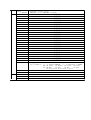
1
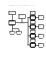
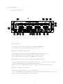
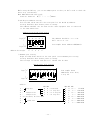
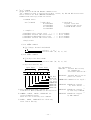
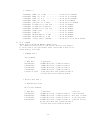
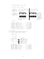
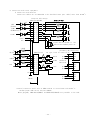
4CH STEPPING MOTOR CONTROLLER
PM4C-05A
USER'S MANUAL
(1149B
APPLICATION
OF
ELECTRONIC
VER.1)
DEVICES
TSUJI ELECTRONICS CO.,LTD
3739 Kandatsu-machi Tsuchiura-city
Ibaraki-Pref 300-0013 Japan
Phone +81-(0)29-832-3031
fax
+81-(0)29-832-2662
URL
http://www.tsujicon.jp
E-mail [email protected]
PM4C−05A
COMMAND
for GP−IB,RS232C (delimiter:CR+LF(fixed))
MODE
R
R/L
R
R/L
R
COMMAND
S100
S101
S110
S111
S120
S121
S130
S131
S18
S19
S200
S201
S202
S210
S211
S212
S220
S221
S222
S230
S231
S232
S30□□
S31□□
S32□□
S33□□
S380
±DDDDDDDHH
LIST
REPLY ETC.
cancel A CH SRQ
GP-IB only
SRQ set when A MOTOR stopped
〃
cancel B CH SRQ
〃
SRQ set when B motor stopped
〃
cancel C CH SRQ
〃
SRQ set when C motor stopped
〃
cancel D CH SRQ
〃
SRQ set when D motor stopped
〃
SRQ flag read
R0□
□:1/A POS., 2/B POS. 3/A,B POS. ・・・
SRQ out CH read R0□
□:1/A POS., 2/B POS. 3/A,B POS. ・・・
A CH position data read RA±DDDDDDD
D:decimal
A CH CPU status read
RAHH
H:hex code, b0 BIT:BUSY
A CH LS, HP, HOLD OFF status read 0:CWLS,b1:CCWLS,b2:HP,b3:H.OFF
B CH position data read RB±DDDDDDD
D:decimal
B CH CPU status read
RBHH
H:hex code, b0 BIT:BUSY
B CH LS, HP, HOLD OFF status read 0:CWLS,b1:CCWLS,b2:HP,b3:H.OFF
C CH position data read RC±DDDDDDD
D:decimal
C CH CPU status read
RCHH
H:hex code, b0 BIT:BUSY
C CH LS, HP, HOLD OFF status read 0:CWLS,b1:CCWLS,b2:HP,b3:H.OFF
D CH position data read RD±DDDDDDD
D:decimal
D CH CPU status read
RDHH
H:hex code, b0 BIT:BUSY
D CH LS, HP, HOLD OFF status read 0:CWLS,b1:CCWLS,b2:HP,b3:H.OFF
A POSITION 2 BYTE COMMAND
□□:COMMAND
08:+JOG,
09:-JOG
0C:+CSPD SCAN
0D:-CSPD SCAN
0E:+SCAN
0F:-SCAN
16:PAUSE ON
17:PAUSE OFF
18:HOLD OFF
19:HOLD ON 1E:+SCAN & HP STOP 1F:-SCAN & HP STOP
40:SLOW STOP 80:EM.STOP
B POSITION 2 BYTE COMMAND
□□:COMMAND
08:+JOG,
09:-JOG
0C:+CSPD SCAN
0D:-CSPD SCAN
0E:+SCAN
0F:-SCAN
16:PAUSE ON
17:PAUSE OFF
18:HOLD OFF
19:HOLD ON 1E:+SCAN & HP STOP 1F:-SCAN & HP STOP
40:SLOW STOP 80:EM.STOP
C POSITION 2 BYTE COMMAND
□□:COMMAND
08:+JOG,
09:-JOG
0C:+CSPD SCAN
0D:-CSPD SCAN
0E:+SCAN
0F:-SCAN
16:PAUSE ON
17:PAUSE OFF
18:HOLD OFF
19:HOLD ON 1E:+SCAN & HP STOP 1F:-SCAN & HP STOP
40:SLOW STOP 80:EM.STOP
D POSITION 2 BYTE COMMAND
□□:COMMAND
08:+JOG,
09:-JOG
0C:+CSPD SCAN
0D:-CSPD SCAN
0E:+SCAN
0F:-SCAN
16:PAUSE ON
17:PAUSE OFF
18:HOLD OFF
19:HOLD ON 1E:+SCAN & HP STOP 1F:-SCAN & HP STOP
40:SLOW STOP 80:EM.STOP
A POSITION DECIMAL INDEX COMMAND
HH: 10:CSPD INDEX SCAN 11:CSPD ABSOLUTE INDEX SCAN
12:INDEX SCAN
13:ABSOLUTE SCAN
R
S381
±DDDDDDDHH
S382
±DDDDDDDHH
S383
±DDDDDDDHH
S3900DDD
S3901DDD
S3902DDD
S3903DD
S3904DDDD
S3905D
S3906D
S3907D
S3908D
S3909
±DDDDDD
S3910DDD
S3911DDD
S3912DDD
S3913DD
S3914DDDD
S3915D
S3916D
S3917D
S3918D
S3919
±DDDDDD
S3920DDD
S3921DDD
S3922DDD
S3923DD
S3924DDDD
S3925D
S3926D
S3927D
S3928D
S3929
±DDDDDD
S3930DDD
S3931DDD
S3932DDD
S3933DD
S3934DDDD
S3935D
S3936D
S3937D
S3938D
B POSITION DECIMAL INDEX COMMAND
HH: 10:CSPD INDEX SCAN 11:CSPD ABSOLUTE INDEX SCAN
12:INDEX SCAN
13:ABSOLUTE SCAN
C POSITION DECIMAL INDEX COMMAND
HH: 10:CSPD INDEX SCAN 11:CSPD ABSOLUTE INDEX SCAN
12:INDEX SCAN
13:ABSOLUTE SCAN
D POSITION DECIMAL INDEX COMMAND
HH: 10:CSPD INDEX SCAN 11:CSPD ABSOLUTE INDEX SCAN
12:INDEX SCAN
13:ABSOLUTE SCAN
A POSITION HSPD set
DDD:3 digit(000∼187)
data available
A POSITION MSPD set
DDD:3 digit(000∼187)
after "S71" command
A POSITION LSPD set
DDD:3 digit(000∼187)
A POSITION RATE set
DD:2 digit( 00∼18 )
A POSITION JOG pulse
DDDD:4 digit(0000∼9999)
A POSITION LS STOP MODE set D: 0:SLOW STOP 1:FAST STOP
A POSITION PB STOP MODE set D: 0:FAST STOP 2:SLOW STOP
A POSITION HOLD OFF set/reset D: 0:set
4:reset
A POSITION HP SCAN DIR set
D: 0:CCW
8:CW
A POSITION counter preset
DDDDDDD:7 digit(0000000∼8388607)
B POSITION HSPD set
DDD:3 digit(000∼187)
data available
B POSITION MSPD set
DDD:3 digit(000∼187)
after "S71" command
B POSITION LSPD set
DDD:3 digit(000∼187)
B POSITION RATE set
DD:2 digit( 00∼18 )
B POSITION JOG pulse
DDDD:4 digit(0000∼9999)
B POSITION LS STOP MODE set D: 0:SLOW STOP 1:FAST STOP
B POSITION PB STOP MODE set D: 0:FAST STOP 2:SLOW STOP
B POSITION HOLD OFF set/reset D: 0:set
4:reset
B POSITION HP SCAN DIR set
D: 0:CCW
8:CW
B POSITION counter preset
DDDDDDD:7 digit(0000000∼8388607)
C POSITION HSPD set
DDD:3 digit(000∼187)
data available
C POSITION MSPD set
DDD:3 digit(000∼187)
after "S71" command
C POSITION LSPD set
DDD:3 digit(000∼187)
C POSITION RATE set
DD:2 digit( 00∼18 )
C POSITION JOG pulse
DDDD:4 digit(0000∼9999)
C POSITION LS STOP MODE set D: 0:SLOW STOP 1:FAST STOP
C POSITION PB STOP MODE set D: 0:FAST STOP 2:SLOW STOP
C POSITION HOLD OFF set/reset D: 0:set
4:reset
C POSITION HP SCAN DIR set
D: 0:CCW
8:CW
C POSITION counter preset
DDDDDDD:7 digit(0000000∼8388607)
D POSITION HSPD set
DDD:3 digit(000∼187)
data available
D POSITION MSPD set
DDD:3 digit(000∼187)
after "S71" command
D POSITION LSPD set
DDD:3 digit(000∼187)
D POSITION RATE set
DD:2 digit( 00∼18 )
D POSITION JOG pulse
DDDD:4 digit(0000∼9999)
D POSITION LS STOP MODE set D: 0:SLOW STOP 1:FAST STOP
D POSITION PB STOP MODE set D: 0:FAST STOP 2:SLOW STOP
D POSITION HOLD OFF set/reset D: 0:set
4:reset
D POSITION HP SCAN DIR set
D: 0:CCW
8:CW
R
R/L
R
S3939
±DDDDDD
S400
S401
S402
S403
S404
S405
S410
S411
S412
S413
S414
S415
S420
S421
S422
S423
S424
S425
S430
S431
S432
S433
S434
S435
S48
S70R
S70L
S71H
S71M
S71L
D POSITION counter preset
DDDDDDD:7 digit(0000000∼8388607)
A POSITION HSPD read
RAH□□□□
A POSITION MSPD read
RAM□□□□
A POSITION LSPD read
RAL□□□□
A POSITION RATE read
RAR□□□□
A POSITION JOG pulse read
RAJP□□□□
A POSITION status read
RAS□□□□
B POSITION HSPD read
RBH□□□□
B POSITION MSPD read
RBM□□□□
B POSITION LSPD read
RBL□□□□
B POSITION RATE read
RBR□□□□
B POSITION JOG pulse read
RBJP□□□□
B POSITION status read
RBS□□□□
C POSITION HSPD read
RCH□□□□
C POSITION MSPD read
RCM□□□□
C POSITION LSPD read
RCL□□□□
C POSITION RATE read
RCR□□□□
C POSITION JOG pulse read
RCJP□□□□
C POSITION status read
RCS□□□□
D POSITION HSPD read
RDH□□□□
D POSITION MSPD read
RDM□□□□
D POSITION LSPD read
RDL□□□□
D POSITION RATE read
RDR□□□□
D POSITION JOG pulse read
RDJP□□□□
D POSITION status read
RDS□□□□
Front panel information read
R〇□HHhh 〇: L:LOCAL R:REMOTE □: C:CONDITION N:NORMAL
HH:b0:A POS. b1:B POS. b2:C POS. b3:D POS.
hh:b0:ABS
b1:IND
b2:H.P
b3:SCAN
b4:H speed b5:M speed b6:L speed
REMOTE MODE CHANGE
LOCAL MODE CHANGE
H SPEED CHANGE
M SPEED CHANGE
L SPEED CHANGE
目
次
1.Abstract
page
1) Characteristics ・・・・・・・・・・・・・・・・・・・・・・・・・・ 2
2) Concept of PM4C control ・・・・・・・・・・・・・・・・・・・・・・ 2
2.Panel layout
1) Front panel layout ・・・・・・・・・・・・・・・・・・・・・・・・ 4
Function SW (in detail) ・・・・・・・・・・・・・・・・・・・・・・ 4
2) Rear panel layout
・・・・・・・・・・・・・・・・・・・・・・・・ 7
3.Setting the motor characteristics
1) Preparation for setting ・・・・・・・・・・・・・・・・・・・・・・ 9
2) HSPD (high speed)
set No.
1 ・・・・・・・・・・・・・ 9
3) MSPD (mid speed)
set No.
2 ・・・・・・・・・・・・・ 9
4) LSPD (low speed)
set No.
3 ・・・・・・・・・・・・・10
5) RATE (speed up/down rate) set No.
4 ・・・・・・・・・・・・・10
6) JGPL (JOG pulse )
set No.
5 ・・・・・・・・・・・・・10
7) MDST (STOP mode )
set No.
6 ・・・・・・・・・・・・・10
table 1.SPEED DATA
table 2.RATE DATA ・・・・・・・・・・・・・11
4.Local mode driving
1) Speed selection ・・・・・・・・・・・・・・・・・・・・・・・・・・12
2) Changing the driving mode ・・・・・・・・・・・・・・・・・・・・・12
3) Channel selection ・・・・・・・・・・・・・・・・・・・・・・・・・12
4) Relative indexed data scan
・・・・・・・・・・・・・・・・・・・12
5) Absolute indexed data scan
・・・・・・・・・・・・・・・・・・・12
6) Scan and stop at home position・・・・・・・・・・・・・・・・・・・12
7) Continuous scan ・・・・・・・・・・・・・・・・・・・・・・・・・・12
8) JOG step・・・・・・・・・・・・・・・・・・・・・・・・・・・・・・13
9) Position counter preset ・・・・・・・・・・・・・・・・・・・・・・13
10) Synchronous driving ・・・・・・・・・・・・・・・・・・・・・・・・13
11) Auto hold-off
・・・・・・・・・・・・・・・・・・・・・・・・・・13
12) HAND BOX operation ・・・・・・・・・・・・・・・・・・・・・・・・13
5.Remote mode driving
1) Contents of communication ・・・・・・・・・・・・・・・・・・・・・13
2) RS232C, GP-IB data communication・・・・・・・・・・・・・・・・・・13
a. Abstract・・・・・・・・・・・・・・・・・・・・・・・・・・・・・13
b. GP-IB port address・・・・・・・・・・・・・・・・・・・・・・・・14
c. RS232C port set ・・・・・・・・・・・・・・・・・・・・・・・・・14
6.Command in detail
1) "S1" command・・・・・・・・・・・・・・・・・・・・・・・・・・・・15
2) "S2" command・・・・・・・・・・・・・・・・・・・・・・・・・・・・15
3) "S3" command・・・・・・・・・・・・・・・・・・・・・・・・・・・・17
4) "S4" command・・・・・・・・・・・・・・・・・・・・・・・・・・・・19
5) "S7" command・・・・・・・・・・・・・・・・・・・・・・・・・・・・20
7.LIMIT SW setting
1) N.O/N.C setting ・・・・・・・・・・・・・・・・・・・・・・・・・・21
8.Connection with outer equipment
1) Connection with motor driver・・・・・・・・・・・・・・・・・・・・22
- 1 -
PM4C−05A
User's Manual
1.Abstract
1) Characteristics
Can control 4 stepping motors at a time.
Can set individual characteristics (HSPD,MSPD,LSPD,RATE,LMSW)
Scan to set position by trapezoidal driving (INDEX mode)
(Absolute/Relative position are available)
Can stop when limit switch is detected.
Limit SW status can be set(N.O/N.C, Enable/Disable) individually.
Can stop by stop push button when scanning.
1 step driving(※ set pulse driving 0∼9999 pulse).
inching driving.
continuous driving(RUN)
H.P STOP driving.
Enabled channel and driving mode are shown by LED lamp.
Can change driving mode.
Can choose slow/EM stop mode when stop push button or Limit SW.
Set data and position data are battery back upped over five years.
Four motors can be driven synchronously.
If start more than one motor, they start synchronously(Local mode).
HAND BOX is useful when checking mechanical position needed by yourself.
By HAND BOX you can choose one of the motors and jog drive direction.
Each channel has LED lamps that indicate LS status and pulse out status.
Hold-off characteristics for each channel
If you start driving hold-off channel, hold-off state is automatically
reset and after driving automatically set to hold-off state.(Local mode)
Hold-off control is also set by communication command.
It has a GP-IB(IEEE-488) and a RS-232C communication port.
One of which is available at a time by switch selection.
2) Concept of PM4C control
Stepping motor controller ;PM4C-05A has ① a CPU which controls the hole of
the system, ② four CPU which control the stepping motors. The four CPU control
four channels independently. Present positions, present velocities, differential
velocities in starting and stopping phase, etc. are stored in the memories as
battery back up, which are read out and renewed any time you need.
- 2 -
<Schematics
of
internal
Push-Button SW
LED Lamp
circuit>
Display
Digital SW
Data Memory
A POSITION
pulse
controlCPU
pulse out
L.S input
Display
Digital SW
Main CPU
Main CPU Bus
B POSITION
pulse
controlCPU
RS232C
com. port
pulse out
L.S input
Display
Digital SW
GP-IB
com. port
C POSITION
pulse
controlCPU
pulse out
L.S input
Display
Digital SW
D POSITION
pulse
controlCPU
- 3 -
pulse out
L.S input
2.Panel layout
1) Front panel layout
① Power switch
It turns on/off the power supply of the unit(PM4C-05A).
The lamp of the switch is on when the power is on.
② Remote/Local mode change SW
The switches on the panel are available when the mode is Local.
The command control are available when the mode is Remote.
This switch changes the mode LOC→REM→LOC alternately.
③ Each Position control data set SW(CONDITION)
You can change speed data, up/down rate data, etc., of each position control
in the condition mode that is made by this switch.
This switch can't work when this unit is Remote mode or driving motors.
④ Control channel select switch
Choose the channels that is to be controlled.
At the local mode or condition mode, pushing these switches change on/off state
which is known by LED display on the switches.
- 4 -
⑤ Preset switch
At Local mode pushing this switch set ±7 digit digital switch data on the panel
to the position counter which is enabled by ④ control channel selection.
At condition mode pushing this switch increment (+1) the data shown in the display.
If you keep the SW to be pushed more than 0.5 seconds, continuous increment,
that is about 50 - 60 per second, is started.
This switch is not available at remote mode.
⑥ Start switch
At local mode pushing this switch start pulse output driving for the channel that
are set by ④ and the mode shown by ⑨ and by the speed shown by ⑪.
When ⑨ indicate nothing (all lamp off) this switch is used for preparation to
SCAN driving. Preparation state is shown by start switch lamp on.
After JOG switch on SCAN starts to the direction that is given by the JOG switch.
At the condition mode pushing this switch increment (+1) the mode of the display.
This switch is not available at remote mode.
⑦ Stop switch
It can stop pulse output both at Local and Remote mode.
At the condition mode pushing this switch decrement (-1) the data shown in the
display.
If you keep the SW to be pushed more than 0.5 seconds, continuous increment,
that is about 50 - 60 per second, is started.
⑧ Jog switch
This switch is for inching that is available except SCAN mode (all lamp off
shown by ⑨)
Throwing on this switch cause pulse output to the CW/CCW direction. 1)
If you keep the SW to be thrown on more than 0.5 seconds or after the end of JOG
pulse number, continuous pulse output is started.
It will stop when you throw off the switch.
This switch is not available at remote mode.
1) Number of pulses are set by JOG pulse number setting (1 to 9999) in the
condition mode 5.
⑨ Run mode LED indicator
⑩ Run mode change switch
The LED lamp (⑨) indicate current run mode and the switch (⑩) change the mode.
These are 4 mode.
1) ABS mode : move to absolute indexed position
Can move to the absolute position that is shown by ±7 digit digital switch.
2) IND mode : move to relative indexed position
Can move to the relative position that is shown by ±7 digit digital switch.
3) H.P mode : move to home position
- 5 -
Continuous scan and stop at home position by home position sensor.
The start direction (CW/CCW) should be set in the condition mode in advance.
4) SCAN mode (all lamp off)
Continuous pulse out to CW or CCW direction.
After preparation (start switch lamp on) of SCAN by START SW(⑥), then decide
scan direction by JOG SW(⑧).
Pulse out can be stopped by STOP button or LIMIT SW.
⑪ Speed select LED indicator
⑫ Speed select switch
The LED lamp (⑪) indicate current set speed and the switch (⑫) select the speed.
These are 3 mode.
1) H SPEED
Pulse out by HSPD data 1) that was set in advance.
2) M SPEED
Pulse out by MSPD data 2) that was set in advance.
3) L SPEED
Pulse out by LSPD data 3) that was set in advance.
1) Speed data (0 - 187) set by condition mode 1 (HSPD setting)
2) Speed data (0 - 187) set by condition mode 1 (MSPD setting)
3) Speed data (0 - 161) set by condition mode 1 (LSPD setting)
※ See speed data table on page 11 table 1.
⑬ Connector for Hand box
It is use for the Hand box attached to PM4C-05A.
To use hand box only connect to the connector here.
⑭ GP-IB line monitor LED
When communication over GP-IB line used these LED lamp indicate listener, talker.
Also SRQ is requested SRQ LED lamp indicates the status.
⑮ Pulse counter data display
At the Local mode, it indicate current position.
Left side of the display window is for the polarity indicate , "-" shows minus and
blank shows plus sign.
An extent of the data is +8388607 ∼ 0 ∼ -8388608.
At the condition mode it display setting data for confirmation.
Left side data shows mode No that is now set, and 4 digit of right side shows
setting data and the other will shows blank.
(See 3. Setting the motor characteristics)
⑯ LED indicator for external switch input
- 6 -
Indicate the status of external switches, LIMIT SW (CW/CCW), H.P LS (H.P).
⑰ Indicator LED for pulse output & hold-off
LED indicates pulse output status, hold-off status.
If the LED lamp is on, it indicate active status.
⑱ ±7 digit digital rotary switch
It gives the data for ABS RUN, IND RUN, PRESET DATA.
④,⑮,⑯,⑰,⑱ above are provided for each channel.
2) Rear panel layout
① AC100V/200V power supply connector
Inlet type AC connector for AC100V/200V power supply.
Use AC cable attached.
② Fuse holder
- 7 -
For safety of AC power line.
3A mini fuse available.
③ Address set switch
For use of GP-IB communication port address.
Address data is read only power on timing.
If Address is changed you must power on the unit again.
(Details are 5.REMOTE mode driving 2. b)
④ GP-IB communication connector
24P connector for GP-IB
⑤ Communication port select switch
Select communication port(RS232C or GP-IB)
Switch status is read only power on timing.
If the status is changed you must power on the unit again.
⑥ Setting switch for RS232C
Set data for RS232C communication.
Switch status is read only power on timing.
If the status is changed you must power on the unit again.
(Details are 5. REMOTE mode driving 2. c)
⑦ RS232C connector
D-Sub 25P (socket type)
⑧ Pulse output connector
Three signals are from this connector, CW, CCW pulse and Hold-off signal.
D-Sub 9P (socket type)
(Connection details are 7. Connection with external equipment)
⑨ External switch input connector
External switches (CW, CCW, Home position limit switch) are connected.
D-Sub 9P (pin type)
(Connection details are 7. Connection with external equipment)
⑩ Limit switch mode change
Can choose mode whether limit switches are enable or disable.
When mode is DISABLE side, pulse output never stop by limit switch.
- 8 -
3.Setting the motor characteristics
In PM4C-05A each data of four stepping motors can be set and stored, which is kept
as battery back up. The data are kept to be memorized until reset. Then accurate
control is realized for any system. In setting mode, pulse out is stopped.
Data can not be set during motor moving.
1) Power on
When Power SW is turned on, status become to be default mode within 1 second.
operation
mode
default
LOCAL
driving
mode
driving
position
REL
memorized
speed
setting
MID
Other data are set as the value which are the one last time turned off the power,
because the all of these data are kept by battery back up.
(Preparation)
a) Set to Local mode by REM/LOC button.
b) Set to Condition mode by CONDITION button.
Then all channel select button lamp are off.
Display window
1
set No
blank
set data
Select channel by channel select button, the display window changes above.
Set number is 1 to 6, and can be changed by DATA button (START button).
Set data can be changed by INC(PRESET)/DEC (STOP) button.
If you keep the SW to be pushed on more than 0.5 seconds, continuous increment or
decrement will start.
2) HSPD (Highest Speed)
Setting No.1
a) Select set No.1 by DATA (START) button.
(It's the state just entered this mode)
b) Set new data by INC (PRESET) button, DEC (STOP) button.
See table 1 about the relation between data and speed.
c) Set data are written as decimal data (0 to 187).
3) MSPD (Medium Speed)
Setting No.2
a) Select set No.2 by DATA (START) button.
b) Set new data by INC (PRESET) button, DEC (STOP) button.
See table 1 about the relation between data and speed.
c) Set data are written as decimal data (0 to 187).
- 9 -
4) LSPD (Low Speed)
Setting No.3
a) Select set No.3 by DATA (START) button.
b) Set new data by INC (PRESET) button, DEC (STOP) button.
See table 1 about the relation between data and speed.
c) Set data are written as decimal data (0 to 161).
5) RATE (Speed up/down rate) Setting No.4
a) Select set No.4 by DATA (START) button.
b) Set new data by INC (PRESET) button, DEC (STOP) button.
See table 2 about the relation between data and rate.
c) Set data are written as decimal data (0 to 18).
6) JOG pulse number
Setting No.5
a) Select set No.5 by DATA (START) button.
b) Set new data by INC (PRESET) button, DEC (STOP) button.
c) Set data are written as decimal data (1 to 9999).
d) The number of JOG pulse is available when jog SW is used (default number = 1).
7) Flags (STOP mode, etc.
Setting No.6
a) Select set No.6 by DATA (START) button.
b) Set new data by INC (PRESET) button, DEC (STOP) button.
c) Set data are written as decimal data (0 to 15).
Details of data
upper 4 bit
1/0
1/0
1/0
lower 4 bit
1/0
1/0
1/0
H.P
not
not
not
not
1/0
1/0
LS STOP mode (1:EM,0:SLOW)
PB STOP mode (1:SLOW,0:EM)
H.OFF (1: set 0: reset)
SCAN DIR (1: CW dir,0: CCW dir)
used
used
used
used
HOLD OFF
IF some torque is required to keep the motor remaining stationary,
power should be kept to be turned on.
But, if there is not such a requirement, some motor drivers can be hold off to
prevent the heating up and to save the power.
When you use these types of drivers, motor can be more effectively driven by
this bit operation. When this bit is 1, hold off signal is disable so that
power is kept to be turned on all time. When this bit is 0 in manual mode,
the power is turned on 0.1s before jog starting, and turned off 0.1S after
jog finishing.
* The motor, whose power is required to be hold off in remote mode,
should be controlled by the sequence, in which the "hold off" is set to be
disable before jog starting, and reset to be enable after jog finishing.
- 10 -
Table 1
No.
000
001
002
003
004
005
006
007
008
009
010
011
012
013
014
015
016
017
018
019
020
021
022
023
024
025
026
027
028
029
030
031
032
033
034
035
036
037
038
039
040
041
042
043
044
045
046
PPS
5
10
25
50
75
100
150
200
250
300
350
400
450
500
550
600
650
700
750
800
900
1000
1100
1200
1300
1400
1500
1600
1700
1800
1900
2000
2100
2200
2300
2400
2500
2600
2700
2800
2900
3000
3100
3200
3300
3400
3500
No.
047
048
049
050
051
052
053
054
055
056
057
058
059
060
061
062
063
064
065
066
067
068
069
070
071
072
073
074
075
076
077
078
079
080
081
082
083
084
085
086
087
088
089
090
091
092
093
PPS
3600
3700
3800
3900
4000
4100
4200
4300
4400
4500
4600
4700
4800
4900
5000
5100
5200
5300
5400
5500
5600
5700
5800
5900
6000
6100
6200
6300
6400
6500
6600
6700
6800
6900
7000
7100
7200
7300
7400
7500
7600
7700
7800
7900
8000
8200
8400
Speed data
No.
094
095
096
097
098
099
100
101
102
103
104
105
106
107
108
109
110
111
112
113
114
115
116
117
118
119
120
121
122
123
124
125
126
127
128
129
130
131
132
133
134
135
136
137
138
139
140
PPS
8600
8800
9000
9200
9400
9600
9800
10000
10200
10400
10600
10800
11010
11210
11410
11600
11800
11990
12200
12400
12600
12790
12990
13200
13400
13620
13810
14000
14200
14400
14620
14830
15010
15200
15390
15580
15770
15970
16180
16400
16610
16830
17060
17240
17420
17600
17800
Table 2
No.
141
142
143
144
145
146
147
148
149
150
151
152
153
154
155
156
157
158
159
160
161
162
163
164
165
166
167
168
169
170
171
172
173
174
175
176
177
178
179
180
181
182
183
184
185
186
187
- 11 -
PPS
17990
18180
18380
18660
18940
19230
19530
19840
20160
20500
20830
21190
21550
21930
22320
22730
23150
23590
24040
24510
25000
25510
26040
26600
27170
27620
28090
28570
29070
29590
30120
30680
31250
31850
32470
33110
33780
34480
35210
35970
36500
37040
37600
38170
38760
39370
40000
No.
000
001
002
003
004
005
006
007
008
009
010
011
012
013
014
015
016
017
018
Rate data
ms/1000 PPS
1000
800
600
500
400
300
200
150
125
100
75
50
30
20
15
10
7.5
5.0
3.0
4.LOCAL mode driving
Only when remote/local SW is set to be local, the motor can be driven in local mode.
If this SW is remote, you need to push the SW once, and reenter into local mode.
1) Speed selection
By use of speed selecting PB, any speed can be selected from the three speed
that are preset in each channel, which are HSPD, MSPD and LSPD.
Starting speed of acceleration and final speed of deceleration is LSPD.
2) Changing the driving mode
By use of driving mode selecting PB, you can select the mode as you like: HP,REL,
ABS and scan(scan mode is the case that all LED which show driving mode are
turned off).
Just after power on, REL mode is selected.
3) Channel select
In LOCAL mode, you can choose the channel that you want to drive by channel
select button A, B, C, D.
4) Relative or incremental indexed scan (RUN mode = IND)
In IND mode when START PB pressed the motor steps relatively by the digital SW data.
If more than one motor is selected, they start synchronously.
After finishing the set pulse out, it stops automatically.
In this mode it can stop by STOP button or limit switch input.
5) Absolute indexed scan (RUN mode = ABS)
In ABS mode when START PB pressed the motor steps to the absolute data that
the digital SW indicate.
If more than one motor is selected, they start synchronously.
After finishing the set pulse out, it stops automatically.
In this mode it can stop by STOP button or limit switch input.
In this mode it can stop by STOP button or limit switch input.
6) Scan and stop at home position (RUN mode = HP)
In HP mode when START PB pressed the motor scans to one direction that are
set in advance in condition mode, then when HP sensor turns on it stops
automatically.
In this mode it can stop by STOP button or limit switch input.
7) Continuous scan (RUN mode = SCAN (all lamp off))
In this mode the motor scans continuously.
When START button is pressed, the lamp on the button is on and prompt to decide
moving direction. Then throw on JOG switch to one direction side you want.
In this mode it can stop by STOP button or limit switch input.
- 12 -
8) Jog driving
In the direction which is set by jog SW, pulses are sent and motor is driven.
If you keep the SW to be pushed more than 0.5 seconds, continuous scan is started.
Then you can stop the pulse by releasing the switch.
This is not available in the SCAN mode.
9) Position counter preset
By PRESET button the digital switch data set to the position counter.
10) Synchronous start driving
You can drive each channel respectively, and also you can start two to four
of them synchronously.
If you select more than one motor, they start synchronously.
11) Auto hold off function
In local mode, the motor, that is set as hold-off state in the condition mode,
clear the hold-off state before starting and set hold-off state after finishing
the scan again.
12) HAND BOX operation
Can use Hand box operation, useful when checking the mechanical move.
The rotary switch on the hand box can choose one of four channels.
JOG switch works as the same one on the front panel.
This function is available only in Local mode.
5.REMOTE mode driving
This mode is possible when remote/local SW shows to be REMT.
If the remote/local SW shows LOCL, push the SW again or send the command
externally to change the mode to be REMT. And, after that, continue to operate
as below. Also remote/local change can be done by communication line.
1) Summary of the communication
data read
CHANNEL POSITION DATA, HSPD, MSPD, LSPD, RATE
STOP MODE & LS, REM/LOC status etc.
data write
HSPD, MSPD, LSPD, RATE, LMSW
Command
+JOG, -JOG, SCAN, CONSTANT SPEED RELATIVE INDEX SCAN,
CONSTANT SPEED ABSOLUTE INDEX SCAN, RELATIVE INDEX,
ABSOLUTE INDEX, SPEED SELECT, PAUSE ON/OFF, HOLD OFF SET/RESET,
SLOW STOP, EMergency STOP
* Data read is available in both REMOTE and LOCAL mode.
2) Communication specification
a) Introduction
A PM4C-05A has a GP-IB control IC;TMS9914A. and has a RS232C control
IC;HD64941. In this system, nonsense command or impossible command(EX. reverse
drive during normal drive)are ignored so that almost all time you can access
from these communication lines (protect from hung up).
Receive form should be S□・・・・□CR+LF. *)
□: ASCII
* de-limitter is fixed to CR+LF.
When CR(0DH)+LF(0AH)is detected during receiving, the command is rapidly analyzed
and done by PM4C-05A. However, if it can't be analyzed, no operation is
done. When PM4C receives information that some data should be returned back,
the data are rapidly prepared and sent back. These operations are done for about
less than 1mS.
- 13 -
While using GP-IB line, you can use SRQ request so that you don't need to check the
motor stop continuously.
When PM4C-05A needs some reply,
Send out forms are R□・・・・・・□CR+LF
b) GP-IB port address setting
Five bit DIP slide switch in the rear panel is for GP-IB my address.
Setting should be done before power on timing.
The address shouldn't be the same as the other equipment that is connected
to the same GP-IB line.
Address setting DIP slide switch
logic"1"
↑
1
2
↓
logic"0"
address bit weight
3
4
5
The address should be 1 to 30.
Don't use 0 or 31.
Left sample shows address 07H(00111).
OFF
24
23
22
21
20
c) RS232C port setting
Eight bit DIP slide switch in the rear panel is for RS232C port setting.
Setting should be done before power on timing.
The settings of counter side (PC etc.) should also be done.
RS232C port setting
logic"1"
↑
↓
logic"0"
1
2
3
4
5
6
7
8
Left sample shows
4800 baud, 8 bit data,
1 stop bit
OFF
SW No.
SW1 SW2
1:
stop bit
0
0 ・・・reserved
2:
0
1 ・・・1 stop bit
3:
always 0 set
1
0 ・・・1.5 stop bit
4:
always 0 set
1
1 ・・・2 stop bit
5:1:8 bit data, 0:7 bit data
6:
7:
baud rate
8:
- 14 -
SW6 SW7 SW8
0
0
0 ・・・
75 BAUD
0
0
1 ・・・ 150 BAUD
0
1
0 ・・・ 300 BAUD
0
1
1 ・・・ 600 BAUD
1
0
0 ・・・ 1200 BAUD
1
0
1 ・・・ 2400 BAUD
1
1
0 ・・・ 4800 BAUD
1
1
1 ・・・ 9600 BAUD
6.Command in detail(for both RS232C and GP-IB)
Command is available only in ASCII code.
De-limitter is fixed to be CR+LF both in send data and receive data.
1) "S1" command
It can be used only GP-IB communication and is for SRQ request on GP-IB line.
It can be used during motor stop state.
If SRQ is set to one channel, SRQ signal occurs when the channel motor stops.
This command is available only in remote mode. 1)
Send form of the commands are below.
The SRQ flags, that were set once before, are cleared at the SRQ send out timing.
<Command form>
S1○△CR+LF
○ mark data
△ mark data
0:A POSITION
1:SRQ set
1:B POSITION
0:SRQ clear
2:C POSITION
3:D POSITION
8:current SRQ flag
9:SRQ reply channel read
<<sample>>
A POSITION SRQ set ・・・・・・S101CR+LF
B POSITION SRQ clear ・・・・・S110CR+LF
Current SRQ flag read
・・・S18CR+LF
SRQ reply channel read
・・S19CR+LF
1) "S18" command is available both remote and local mode.
2) Can get channel information that replied SRQ by "S19" command.
After reply to "S19" command, channel information is cleared in the memory.
7
0
Reply to "S18", "S19" command
<Reply form>
R0□CR+LF
"0"
A
B
C
D
- 15 -
POSITION(1)
POSITION(2)
POSITION(4)
POSITION(8)
□ is total value
of 1,2,4,8 in hex.
2) "S2" command
Useful both in GP-IB and RS232C communication.
"S2" command is used to read position data, status, LS, HP and Hold-off status.
Can be used in all mode (REM/LOC/CONDITION).
Command form and reply forms are below.
<Command form>
S2○△CR+LF
○ mark
0:A
1:B
2:C
3:D
data
POSITION
POSITION
POSITION
POSITION
△ mark data
0:pulse count data
1:internal CPU status
2:LS・HP・H.OFF status
<<sample>>
A
B
C
D
POSITION
POSITION
POSITION
POSITION
pulse counter read
・・・・・・S200CR+LF
internal CPU status read ・・・・S211CR+LF
LS・HP・H.OFF status read
・・・S222CR+LF
internal CPU status read ・・・・S231CR+LF
<Reply form>
a) For S2※0 command
R○△(7digit decimal data)CR+LF
↑↑
polarity + or −
position name (A,B,C,D)
b) For S2※1 command
R○(2 digit hex data) CR+LF
↑
position name (A,B,C,D)
2 digit hex data bit map
upper digit
lower digit
7
↑
bit information
BUSY BIT : internal CPU is busy
any command are
receivable when bit=0
0
↑
↑
↑
↑
↑
↑
↑
BUSY BIT
DRIVE BIT
not used
not used
COMERR BIT
LSEND BIT
SSEND BIT
ESEND BIT
DRIVE BIT: internal CPU is now on
pulse out status.
COMERR BIT:command is not regal
LSEND BIT :PULSE was stopped
by limit switch.
2,3)
1) Only SLOW STOP,EM STOP command are
available in BUSY=1,DRIVE=1(on driving)state.
SSEND BIT :PULSE was stopped 2,3)
by slow stop command.
2) COMERR , LSEND , SSEND , ESEND BIT are
valid in BUSY=0 status.
These bit are cleared by next command.
ESEND BIT :PULSE was stopped
by EM command.
3) LSEND , SSEND , ESEND BIT are valid only
after end of driving.
- 16 -
1)
2,3)
2)
C) For S2※2 command
R○(1 digit HEX data) CR+LF
↑
position name (A,B,C,D)
1 digit hex data bit map
23
22
21
20
↑
↑
↑
↑
CW LS status (0:NON ACTIVE 1:ACTIVE)
CCW LS status(0:NON ACTIVE 1:ACTIVE)
HP LS status (0:NON ACTIVE 1:ACTIVE)
H.OFF status (0:H.ON 1:H.OFF)
3) "S3" command
Useful both in GP-IB and RS232C communication.
"S3" command is used to pulse out or pulse stop and set condition data.
If the channel is scanning (BUSY BIT=1) these commands are ignored except pulse
stop command.
<Command form
type 1>
S3○(2 digit HEX data)CR+LF
○ mark data
0:A POSITION
1:B POSITION
2:C POSITION
3:D POSITION
2 digit HEX data
08,0A:+JOG(1 pulse)
09,0B:-JOG(1 pulse)
0C:+SCAN(no acc.)
0D:-SCAN(no acc.)
0E:+SCAN(with acc.)
0F:-SCAN(with acc.)
16:PAUSE ON 1)
17:PAUSE OFF 1)
18:HOLD OFF set
19:HOLD OFF clear
1E:HP STOP +SCAN(with acc.)
1F:HP STOP -SCAN(with acc.)
40:SLOW STOP
80:EM STOP
1) PAUSE on/off command
controls one circuit
line on the board,
any position mark
(A,B,C,D) will work
as the same command.
<<sample>>
A POSITION +JOG command ・・・・・・・S3008CR+LF(or S300ACR+LF)
B POSITION HOLD OFF set ・・・・・・・S3118CR+LF
C POSITION +SCAN command ・・・・・・S320ECR+LF
D POSITION slow stop command ・・・・・S3340CR+LF
- 17 -
<Command form type 2>
S38○(±7 digit decimal data)(2 digit HEX data)CR+LF
○ mark data
0:A POSITION
1:B POSITION
2:C POSITION
3:D POSITION
2 digit HEX data
10:INDEX SCAN
(no acceleration)
11:ABSOLUTE SCAN(no acceleration)
12:INDEX SCAN
(acceleration)
13:ABSOLUTE SCAN(acceleration)
※±7 digit decimal data must be within ±8388607(0 ∼ FFFFFFH in HEX)
<<sample>>
A
B
C
D
POSITION
POSITION
POSITION
POSITION
+1234567
-0200000
+0000000
-0000100
INDEX SCAN(no acc.) ・・・・S380+123456710CR+LF
ABSOLUTE SCAN(no acc.)・・・S381−020000011CR+LF
INDEX SCAN(with acc.) ・・・S382+000000012CR+LF
ABSOLUTE SCAN(with acc.)・・S383−000010013CR+LF
<Command form type 3>
S39○△<const.1>CR+LF
○ mark data
0:A POSITION
1:B POSITION
2:C POSITION
3:D POSITION
△ mark data
0:HSPD change
1:MSPD change
2:LSPD change
3:RATE change
4:JOG pulse set
5:LS STOP MODE set
6:PB STOP MODE set
7:H.OFF set/clear
8:HP SCAN DIR set
9:counter preset
const.1
3 digit(000∼187) 2)
3 digit(000∼187) 2)
3 digit(000∼161) 2)
3)
2 digit(00∼18)
4 digit(0000∼9999) 4)
1 digit(0:SLOW STOP 1:EM STOP)
1 digit(0:EM STOP 2:SLOW STOP)
1 digit(0:clear 4:set)
1 digit(0:CCW
8:CW )
±7 digit decimal(max±8388607)
2) It must be 3 digit data
3) It must be 2 digit data
4) It must be 4 digit data
<<<<<
Caution
>>>>>
※ Speed data change by this "S39" needs "S71" command to effective new data.
"S71" command is the sign to start changing speed data.
- 18 -
<<sample>>
A
B
C
D
A
B
C
D
A
B
C
D
A
POSITION
POSITION
POSITION
POSITION
POSITION
POSITION
POSITION
POSITION
POSITION
POSITION
POSITION
POSITION
POSITION
HSPD set to 100
・・・・・・・S3900100CR+LF
MSPD set to 15 ・・・・・・・・S3911015CR+LF
LSPD set to 5
・・・・・・・・S3922005CR+LF
RATE set to 10 ・・・・・・・・S393310CR+LF
JOG pulse set to 1234
・・・・S39041234CR+LF
LS STOP set to slow stop ・・・・S39150CR+LF
LS STOP set to EM stop ・・・・・S39251CR+LF
PB STOP set to slow stop ・・・・S39362CR+LF
H.OFF clear
・・・・・・・・・S39070CR+LF
H.OFF set
・・・・・・・・・S39174CR+LF
HP SCAN DIR set to CCW
・・・・S39280CR+LF
HP SCAN DIR set to CW ・・・・・S39388CR+LF
counter preset +1234567・・・・・S3909+1234567CR+LF
4) "S4" command
Useful both in GP-IB and RS232C communication.
"S4" command is mainly used to read setting data for each channel.
It can be used at any time whether pulse control CPU is busy or not,
remote mode or local mode.
< Command form >
S4○△CR+LF
○ mark data
0:A POSITION
1:B POSITION
2:C POSITION
3:D POSITION
8:status of panel
△ mark data
0:HSPD data read (condition mode 1)
1:MSPD data read (condition mode 2)
2:LSPD data read (condition mode 3)
3:RATE data read (condition mode 4)
4:JOG pulse data read (condition mode 5)
5:status data read (condition mode 6)
< Receive data form >
a) POSITION data read
R○□<const.2>CR+LF
○ mark data
A:A POSITION
B:B POSITION
C:C POSITION
D:D POSITION
□ mark data
H:HSPD data read (condition mode 1)
M:MSPD data read (condition mode 2)
L:LSPD data read (condition mode 3)
R:RATE data read (condition mode 4)
JP:JOG pulse data read (condition mode
S:status data read (condition mode 6)
- 19 -
const.2 is
4 digit decimal
data that is shown
in the panel when
condition setting.
5)
b) Status information for the panel
R○□<const.3><const.4>CR+LF
○ mark data
L:LOCAL mode
R:REMOTE mode
□ mark data
C:CONDITIONmode
N:NORMAL mode
const.3 is 2 digit hex
code as the bit pattern
shown below.
upper
lower
F
F
7
B0:A POS.
B1:B POS.
B2:C POS.
0
B3:D POS.
B4∼B7:0
const.4 is 2 digit hex
code as the bit pattern
shown below.
upper
lower
B0:ABS mode
F
F
B1:IND mode
7
0
B2:H.P mode
B3:SCAN mode
B4:SPEED Low
B5:SPEED Mid
B6:SPEED Hi
B7:0
<<sample>>
A POSITION HSPD data read ・・・・・・S400CR+LF
B POSITION MSPD data read ・・・・・・S411CR+LF
C POSITION LSPD data read ・・・・・・S422CR+LF
D POSITION RATE data read ・・・・・・S433CR+LF
A POSITION JOG pulse data read・・・・S404CR+LF
D POSITION status data read・・・・・ S435CR+LF
status information for the panel ・・・S48CR+LF
5) "S7" command
Useful both in GP-IB and RS232C communication.
It is used to change status of the panel.
<Command form>
S7○△CR+LF
○ mark data
0:REM/LOC change
1:SPEED
change
△ mark data
R:REMOTE MODE change
L:LOCAL MODE change
H:SPEED Hi change
M:SPEED Mid change
L:SPEED Low change
<<sample>>
PM4C-05A REMOTE mode change
・・・・S70RCR+LF
PM4C-05A LOCAL mode change ・・・・・S70LCR+LF
PM4C-05A SPEED Hi change
・・・・・S71HCR+LF
PM4C-05A SPEED Mid change
・・・・S71MCR+LF
PM4C-05A SPEED Low change
・・・・S71LCR+LF
- 20 -
7.LIMIT SW logical setting
Logical setting switch for the external limit switches are on the main board.
If you need logical change for the limit switches, you can remove upper cover
and treat switches as follows.
<<< Warning !! >>>
Be sure to disconnect main power supply cable before this process!
Board No. TE460−1
Switch No. for A and Bch:SW5
for C and Dch:SW6
TE460-1
SW
5
SW
6
SW5,6 details
O N
↑
↓
OFF
1
2
3
4
5
6
OFF
1:A(C)
2:B(D)
3:A(C)
4:A(C)
5:B(D)
6:B(D)
POSITION
POSITION
POSITION
POSITION
POSITION
POSITION
H.P
H.P
CW LS
CCW LS
CW LS
CCW LS
(default status is shown)
Default status is set CW・CCW as N.C and H.P as N.O.
- 21 -
ON: A(N.O) type
OFF: B(N.C) type
ON: B(N.C) type
OFF: A(N.O) type
8. Connection with outer equipment
1) Connection with drivers
Connection cables are recommended to be shielded twist pair cable( more than 0.2mm2).
connector PIN assign
DE9S(TO DRIVER)
Driver
+5V
CWP
(PULSE)
CCWP
(DIRECTION)
1
2
3
4
5
6
7
8
9
H.OFF
+12V→
0V→
○
○
○
○
○
○
○
○
○
300Ω
signal which informs to the
driver that PM16C power on.
1KΩ
CW LS
DE9P(TO LS)
CCWLS
H.P
FG
1
2
3
4
5
6
7
8
9
○
○
○
○
○
○
○
○
○
proximity SW connection
LS type: both N.O and N.C ok
12V
CW LS
1P
SIG
2P
0V
CCWLS
12VTotal
Max.0.8A
12V
H.P
3P
SIG
4P
0V
6P
7P
PM16C
12V
SIG
0V
caution)Connector shell size of DE9P and 9S is varied from each maker's.
Outward form <35W can be used for PM16C.
DE-C1-J6(JAE), XM2S-0911(OMRON) and HDE-CTF(HIROSE) are possible to be used.
- 22 -


![RICE-001 - FAST CORPORATION[株式会社ファースト]](http://vs1.manualzilla.com/store/data/006601846_2-f02a086b647f2e932a69a7ee5745b54b-150x150.png)
![ARN-60520_521取扱説明書 Ver.2.02[PDF:332.1KB]](http://vs1.manualzilla.com/store/data/006533887_2-7498a4686ceb3fc57fd3d84b591131ce-150x150.png)