1
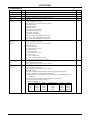
LC87F7932B Operating Temperature Range • -40°C to +85°C Ports • Normal withstand voltage I/O ports Ports whose input/output can be programmed in 1-bit units: Multiplexed functions Input ports (for debugger): LCD ports (segment output): • LCD ports/general purpose I/O ports Segment output: Common output: Bias power supply for LCD driving Multiplexed functions Input/output ports: • Oscillator pins: • Reset pin: • Power supply: 21 (P0n, P1n, P30, P70 to P73) 3 (DBGP0 (P05) to DBGP2 (P07)) 8 (P1n) 32 (S00 to S31) 4 (COM0 to COM3) 5 (V1 to V3, CUP1, CUP2) 36 (LPAn, LPBn, LPCn, LPL0 to LPL3, P1n) 4 (CF1, CF2, XT1, XT2) 1 (RES) 5 (VSS1, VSS2, VDD1, VDD2, V2) LCD Controller (1) Seven display modes are available (2) Duty: 1/3 duty, 1/4 duty (3) Bias: 1/2 bias, 1/3 bias (4) Segment/common output can be switched to general purpose I/O ports. (5) LCD power range 1) 1/3 bias V1: 1.2V to 1.8V V2: 2.4V to 3.6V V3: 3.6V to 5.4V An LCD panel that supports the V2 (=VDD) × 1.5[V] must be used when 1/3 bias is selected. If the supply voltage VDD is 3.0V, for example, use an LCD panel that supports 4.5V. 2) 1/2 bias V1: 1.2V to 1.8V V2: 2.4V to 3.6V V3: 2.4V to 3.6V (Connect V2 and V3 externally.) An LCD panel that supports the V2 (=VDD)[V] must be used when 1/2 bias is selected. If the supply voltage VDD is 3.0V, for example, use an LCD panel that supports 3.0V. Timers • Timer 0: 16 bit timer/counter with a capture register Mode 0: 8-bit timer with an 8-bit programmable prescaler (with two 8-bit capture registers) × 2 channels Mode 1: 8 bit timer with an 8-bit programmable prescaler (with an 8-bit capture register) + 8-bit counter (with an 8-bit capture register) Mode 2: 16 bit timer with an 8-bit programmable prescaler (with a 16-bit capture register) Mode 3: 16 bit counter (with a 16 bit capture register) • Timer 1: 16 bit timer/counter that supports PWM/toggle output Mode 0: 8-bit timer with an 8-bit prescaler (with toggle output) + 8-bit timer/counter (with toggle output) Mode 1: 8-bit PWM with an 8-bit prescaler × 2 channels Mode 2: 16 bit timer/counter with an 8-bit prescaler (with toggle output) (Toggle outputs also from the low-order 8 bits) Mode 3: 16 bit timer with an 8-bit prescaler (with toggle output) (The low-order 8 bits can be used as a PWM.) • Timer 4: 8-bit timer with a 6-bit prescaler • Timer 5: 8-bit timer with a 6-bit prescaler • Timer 6: 8-bit timer with a 6-bit prescaler (with toggle output) • Timer 7: 8-bit timer with a 6-bit prescaler (with toggle output) • Base Timer (1) The clock can be selected from any of the following: Subclock (32.768kHz crystal oscillator/low-speed RC oscillator), system clock, and timer 0 prescaler output. (2) Interrupts can be generated at five specified time intervals. No.A1841-2/30