1
SECTION 6
QUEUED SERIAL MODULE
This section is an overview of the queued serial module (QSM). Refer to the QSM
Reference Manual (QSMRM/AD) for complete information about the QSM. Refer to
APPENDIX D REGISTER SUMMARY for a QSM address map and register bit and
field definitions.
6.1 General
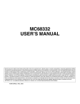
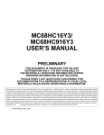
The QSM contains two serial interfaces, the queued serial peripheral interface (QSPI)
and the serial communication interface (SCI). Figure 6-1 is a block diagram of the
QSM.
MISO/PQS0
MOSI/PQS1
SCK/PQS2
PCS0/SS/PQS3
PCS1/PQS4
PCS2/PQS5
PCS3/PQS6
PORT QS
IMB
QSPI
INTERFACE
LOGIC
TXD/PQS7
SCI
RXD
QSM BLOCK
Figure 6-1 QSM Block Diagram
MC68332
USER’S MANUAL
QUEUED SERIAL MODULE
Rev. 15 Oct 2000
MOTOROLA
6-1
The QSPI provides peripheral expansion or interprocessor communication through a
full-duplex, synchronous, three-line bus. Four programmable peripheral chip-selects
can select up to sixteen peripheral devices by using an external one of sixteen line
selector. A self-contained RAM queue allows up to sixteen serial transfers of eight to
sixteen bits each or continuous transmission of up to a 256-bit data stream without
CPU32 intervention. A special wrap-around mode supports continuous transmission/
reception modes.
The SCI provides a standard non-return to zero (NRZ) mark/space format. It operates
in either full- or half-duplex mode. There are separate transmitter and receiver enable
bits and dual data buffers. A modulus-type baud rate generator provides rates from
110 baud to 781 kbaud with a 25.17 MHz system clock. Word length of either eight or
nine bits is software selectable. Optional parity generation and detection provide either
even or odd parity check capability. Advanced error detection circuitry catches glitches
of up to 1/16 of a bit time in duration. Wake-up functions allow the CPU32 to run uninterrupted until meaningful data is available.
6.2 QSM Registers and Address Map
There are four types of QSM registers: QSM global registers, QSM pin control registers, QSPI registers, and SCI registers. Refer to 6.2.1 QSM Global Registers and
6.2.2 QSM Pin Control Registers for a discussion of global and pin control registers.
Refer to 6.3.1 QSPI Registers and 6.4.1 SCI Registers for further information about
QSPI and SCI registers. Writes to unimplemented register bits have no effect, and
reads of unimplemented bits always return zero. Refer to 5.2.1 Module Mapping for
more information about how the state of MM affects the system.
6.2.1 QSM Global Registers
The QSM configuration register (QSMCR) controls the interface between the QSM
and the intermodule bus. The QSM test register (QTEST) is used during factory test
of the QSM. The QSM interrupt level register (QILR) determines the priority of interrupts requested by the QSM and the vector used when an interrupt is acknowledged.
The QSM interrupt vector register (QIVR) contains the interrupt vector for both QSM
submodules. QILR and QIVR are 8-bit registers located at the same word address.
6.2.1.1 Low-Power Stop Mode Operation
When the STOP bit in QSMCR is set, the system clock input to the QSM is disabled
and the module enters a low-power operating state. QSMCR is the only register guaranteed to be readable while STOP is asserted. The QSPI RAM is not readable during
LPSTOP. However, writes to RAM or any register are guaranteed valid while STOP is
asserted. STOP can be set by the CPU32 and by reset.
MC68332
USER’S MANUAL
QUEUED SERIAL MODULE
Rev. 15 Oct 2000
MOTOROLA
6-2
System software must bring the QSPI and SCI to an orderly stop before asserting
STOP to avoid data corruption. The IRQ mask level in the CPU32 status register
should be set to a higher value than the IRQ level generated by the QSM module. The
SCI receiver and transmitter should be disabled after transfers in progress are complete. The QSPI can be halted by setting the HALT bit in SPCR3 and then setting
STOP after the HALTA flag is set. The IRQ mask in the CPU status register should be
restored to its former level. Refer to 5.3.4 Low-Power Operation for more information
about low-power stop mode.
6.2.1.2 Freeze Operation
The FRZ[1:0] bits in QSMCR are used to determine what action is taken by the QSM
when the IMB FREEZE signal is asserted. FREEZE is asserted when the CPU32
enters background debug mode. At the present time, FRZ0 has no effect; setting FRZ1
causes the QSPI to halt on the first transfer boundary following FREEZE assertion.
Refer to 4.10.2 Background Debug Mode for more information.
6.2.1.3 QSM Interrupts
Both the QSPI and SCI can generate interrupt requests. Each has a separate interrupt
request priority register. A single vector register is used to generate exception vector
numbers.
The values of the ILQSPI and ILSCI fields in QILR determine the priority of QSPI and
SCI interrupt requests. The values in these fields correspond to internal interrupt
request signals IRQ[7:1]. A value of %111 causes IRQ7 to be asserted when a QSM
interrupt request is made. Lower field values cause correspondingly lower-numbered
interrupt request signals to be asserted. Setting the ILQSPI or ILSCI field values to
%000 disables interrupts for the respective section. If ILQSPI and ILSCI have the
same non-zero value, and the QSPI and SCI make simultaneous interrupt requests,
the QSPI has priority.
When the CPU32 acknowledges an interrupt request, it places the value in the status
register interrupt priority (IP) mask on the address bus. The QSM compares the IP
mask value to the priority of the request to determine whether it should contend for
arbitration priority. Arbitration priority is determined by the value of the IARB field in
QSMCR. Each module that generates interrupts must have a non-zero IARB value.
Arbitration is performed by means of serial contention between values stored in individual module IARB fields.
When the QSM wins interrupt arbitration, it responds to the CPU32 interrupt acknowledge cycle by placing an interrupt vector number on the data bus. The vector number
is used to calculate displacement into the CPU32 exception vector table. SCI and
QSPI vector numbers are generated from the value in the QIVR INTV field. The values
of bits INTV[7:1] are the same for QSPI and SCI. The value of INTV0 is supplied by
the QSM when an interrupt request is made. INTV0 = 0 for SCI interrupt requests;
INTV0 = 1 for QSPI interrupt requests.
MC68332
USER’S MANUAL
QUEUED SERIAL MODULE
Rev. 15 Oct 2000
MOTOROLA
6-3
At reset, INTV[7:0] is initialized to $0F, the uninitialized interrupt vector number. To
enable interrupt-driven serial communication, a user-defined vector number must be
written to QIVR, and interrupt handler routines must be located at the addresses
pointed to by the corresponding vector. Writes to INTV0 have no effect. Reads of
INTV0 return a value of one.
Refer to SECTION 4 CENTRAL PROCESSOR UNIT and SECTION 5 SYSTEM
INTEGRATION MODULE for more information about exceptions and interrupts.
6.2.2 QSM Pin Control Registers
The QSM uses nine pins. Eight of the pins can be used for serial communication or for
parallel I/O. Clearing a bit in the port QS pin assignment register (PQSPAR) assigns
the corresponding pin to general-purpose I/O; setting a bit assigns the pin to the QSPI.
PQSPAR does not affect operation of the SCI.
The port QS data direction register (DDRQS) determines whether pins are inputs or
outputs. Clearing a bit makes the corresponding pin an input; setting a bit makes the
pin an output. DDRQS affects both QSPI function and I/O function. DDQS7 determines the direction of the TXD pin only when the SCI transmitter is disabled. When the
SCI transmitter is enabled, the TXD pin is an output.
The port QS data register (PORTQS) latches I/O data. PORTQS writes drive pins
defined as outputs. PORTQS reads return data present on the pins. To avoid driving
undefined data, first write PORTQS, then configure DDRQS.
PQSPAR and DDRQS are 8-bit registers located at the same word address. For a
summary of QSM pin functions, refer to Table 6-1.
MC68332
USER’S MANUAL
QUEUED SERIAL MODULE
Rev. 15 Oct 2000
MOTOROLA
6-4
Table 6-1 Effect of DDRQS on QSM Pin Function
QSM Pin
QSPI Mode
DDRQS Bit
Master
MISO
DDQS0
Slave
Master
MOSI
DDQS1
Slave
SCK1
Master
Slave
DDQS2
Master
PCS0/SS
DDQS3
Slave
Master
PCS[1:3]
DDQS[4:6]
Slave
Bit State
Pin Function
0
Serial data input to QSPI
1
Disables data input
0
Disables data output
1
Serial data output from QSPI
0
Disables data output
1
Serial data output from QSPI
0
Serial data input to QSPI
1
Disables data input
—
Clock output from QSPI
—
Clock input to QSPI
0
Assertion causes mode fault
1
Chip-select output
0
QSPI slave select input
1
Disables slave select Input
0
Disables chip-select output
1
Chip-select output
0
Inactive
1
Inactive
2
—
DDQS7
X
Serial data output from SCI
RXD
—
None
NA
Serial data input to SCI
TXD
NOTES:
1. PQS2 is a digital I/O pin unless the SPI is enabled (SPE set in SPCR1), in which case it
becomes the QSPI serial clock SCK.
2. PQS7 is a digital I/O pin unless the SCI transmitter is enabled (TE set in SCCR1), in
which case it becomes the SCI serial data output TXD.
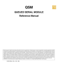
6.3 Queued Serial Peripheral Interface
The queued serial peripheral interface (QSPI) is used to communicate with external
devices through a synchronous serial bus. The QSPI is fully compatible with SPI systems found on other Motorola products, but has enhanced capabilities. The QSPI can
perform full duplex three-wire or half duplex two-wire transfers. A variety of transfer
rates, clocking, and interrupt-driven communication options is available.
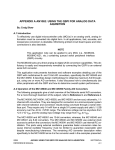
Figure 6-2 displays a block diagram of the QSPI.
MC68332
USER’S MANUAL
QUEUED SERIAL MODULE
Rev. 15 Oct 2000
MOTOROLA
6-5
QUEUE CONTROL
BLOCK
QUEUE
POINTER
COMPARATOR
4
A
D
D
R
E
S
S
DONE
4
END QUEUE
POINTER
80-BYTE
QSPI RAM
R
E
G
I
S
T
E
R
CONTROL
LOGIC
STATUS
REGISTER
CONTROL
REGISTERS
4
LOGIC ARRAY
PROGRAMMABLE
DELAY
COUNTER
CHIP SELECT
4
COMMAND
MSB
M
S
LSB
8/16-BIT SHIFT REGISTER
MOSI
Rx/Tx DATA REGISTER
M
S
MISO
PCS0/SS
2
PCS[2:1]
BAUD RATE
GENERATOR
SCK
QSPI BLOCK
Figure 6-2 QSPI Block Diagram
Serial transfers of eight to sixteen can be specified. Programmable transfer length simplifies interfacing to devices that require different data lengths.
An inter-transfer delay of 17 to 8192 system clocks can be specified (default is 17 system clocks). Programmable delay simplifies the interface to devices that require
different delays between transfers.
MC68332
USER’S MANUAL
QUEUED SERIAL MODULE
Rev. 15 Oct 2000
MOTOROLA
6-6
A dedicated 80-byte RAM is used to store received data, data to be transmitted, and
a queue of commands. The CPU32 can access these locations directly. This allows
serial peripherals to be treated like memory-mapped parallel devices.
The command queue allows the QSPI to perform up to 16 serial transfers without
CPU32 intervention. Each queue entry contains all the information needed by the
QSPI to independently complete one serial transfer.
A pointer identifies the queue location containing the data and command for the next
serial transfer. Normally, the pointer address is incremented after each serial transfer,
but the CPU32 can change the pointer value at any time. Support of multiple-tasks can
be provided by segmenting the queue.
The QSPI has four peripheral chip-select pins. The chip-select signals simplify interfacing by reducing CPU32 intervention. If the chip-select signals are externally
decoded, 16 independent select signals can be generated.
Wrap-around mode allows continuous execution of queued commands. In wraparound mode, newly received data replaces previously received data in the receive
RAM. Wrap-around mode can simplify the interface with A/D converters by continuously updating conversion values stored in the RAM.
Continuous transfer mode allows transfer of an uninterrupted bit stream. Any number
of bits in a range from 8 to 256 can be transferred without CPU32 intervention. Longer
transfers are possible, but minimal intervention is required to prevent loss of data. A
standard delay of 17 system clocks is inserted between the transfer of each queue
entry.
6.3.1 QSPI Registers
The programmer’s model for the QSPI consists of the QSM global and pin control registers, four QSPI control registers (SPCR[0:3]), the status register (SPSR), and the 80byte QSPI RAM. Registers and RAM can be read and written by the CPU32. Refer to
APPENDIX D REGISTER SUMMARY for register bit and field definitions.
6.3.1.1 Control Registers
Control registers contain parameters for configuring the QSPI and enabling various
modes of operation. The CPU32 has read and write access to all control registers. The
QSM has read access only to all bits except the SPE bit in SPCR1. Control registers
must be initialized before the QSPI is enabled to ensure proper operation. SPCR1
must be written last because it contains the QSPI enable bit (SPE).
Writing a new value to any control register except SPCR2 while the QSPI is enabled
disrupts operation. SPCR2 is buffered. New SPCR2 values become effective after
completion of the current serial transfer. Rewriting NEWQP in SPCR2 causes execution to restart at the designated location. Reads of SPCR2 return the current value of
the register, not of the buffer. Writing the same value into any control register except
SPCR2 while the QSPI is enabled has no effect on QSPI operation.
MC68332
USER’S MANUAL
QUEUED SERIAL MODULE
Rev. 15 Oct 2000
MOTOROLA
6-7
6.3.1.2 Status Register
SPSR contains information concerning the current serial transmission. Only the QSPI
can set the bits in this register. The CPU32 reads SPSR to obtain QSPI status information and writes SPSR to clear status flags.
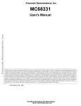
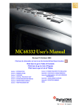
6.3.2 QSPI RAM
The QSPI contains an 80-byte block of dual-ported static RAM that can be accessed
by both the QSPI and the CPU32. The RAM is divided into three segments: receive
data RAM, transmit data RAM, and command data RAM. Receive data is information
received from a serial device external to the MCU. Transmit data is information stored
for transmission to an external device. Command control data defines transfer parameters. Refer to Figure 6-3, which shows RAM organization.
500
51E
RR0
RR1
RR2
520
TR0
TR1
TR2
540
CR0
CR1
CR2
RECEIVE
RAM
TRANSMIT
RAM
COMMAND
RAM
RRD
RRE
RRF
TRD
TRE
TRF
CRD
CRE
CRF
WORD
53E
54F
WORD
BYTE
QSPI RAM MAP
Figure 6-3 QSPI RAM
6.3.2.1 Receive RAM
Data received by the QSPI is stored in this segment. The CPU32 reads this segment
to retrieve data from the QSPI. Data stored in the receive RAM is right-justified.
Unused bits in a receive queue entry are set to zero by the QSPI upon completion of
the individual queue entry. The CPU32 can access the data using byte, word, or longword addressing.
The CPTQP value in SPSR shows which queue entries have been executed. The
CPU32 uses this information to determine which locations in receive RAM contain
valid data before reading them.
MC68332
USER’S MANUAL
QUEUED SERIAL MODULE
Rev. 15 Oct 2000
MOTOROLA
6-8
6.3.2.2 Transmit RAM
Data that is to be transmitted by the QSPI is stored in this segment and must be written
by the CPU32 in right-justified form. The QSPI cannot modify information in the
transmit RAM. The QSPI copies the information to its data serializer for transmission.
Information remains in the transmit RAM until overwritten.
6.3.2.3 Command RAM
Command RAM is used by the QSPI in master mode. The CPU32 writes one byte of
control information to this segment for each QSPI command to be executed. The QSPI
cannot modify information in command RAM.
Command RAM consists of 16 bytes. Each byte is divided into two fields. The peripheral chip-select field enables peripherals for transfer. The command control field
provides transfer options.
A maximum of 16 commands can be in the queue. Queue execution by the QSPI proceeds from the address in NEWQP through the address in ENDQP (both of these
fields are in SPCR2).
6.3.3 QSPI Pins
The QSPI uses seven pins. These pins can be configured for general-purpose I/O
when not needed for QSPI application.
Table 6-2 shows QSPI input and output pins and their functions.
Table 6-2 QSPI Pins
Pin Names
Mnemonics
Mode
Function
Master In Slave Out
MISO
Master
Slave
Serial data input to QSPI
Serial data output from QSPI
Master Out Slave In
MOSI
Master
Slave
Serial data output from QSPI
Serial data input to QSPI
Serial Clock
SCK
Master
Slave
Clock output from QSPI
Clock input to QSPI
Peripheral Chip Selects
PCS[3:1]
Master
Select peripherals
Slave Select
PCS0/SS
Master
Master
Slave
Selects peripherals
Causes mode fault
Initiates serial transfer
6.3.4 QSPI Operation
The QSPI uses a dedicated 80-byte block of static RAM accessible by both the QSPI
and the CPU32 to perform queued operations. The RAM is divided into three segments. There are 16 command bytes, 16 transmit data words, and 16 receive data
words. QSPI RAM is organized so that one byte of command data, one word of transmit data, and one word of receive data correspond to one queue entry, $0–$F.
MC68332
USER’S MANUAL
QUEUED SERIAL MODULE
Rev. 15 Oct 2000
MOTOROLA
6-9
The CPU32 initiates QSPI operation by setting up a queue of QSPI commands in command RAM, writing transmit data into transmit RAM, then enabling the QSPI. The
QSPI executes the queued commands, sets a completion flag (SPIF), and then either
interrupts the CPU32 or waits for intervention.
There are four queue pointers. The CPU32 can access three of them through fields in
QSPI registers. The new queue pointer(NEWQP), contained in SPCR2, points to the
first command in the queue. An internal queue pointer points to the command currently
being executed. The completed queue pointer(CPTQP), contained in SPSR, points to
the last command executed. The end queue pointer (ENDQP), contained in SPCR2,
points to the final command in the queue.
The internal pointer is initialized to the same value as NEWQP. During normal operation, the command pointed to by the internal pointer is executed, the value in the
internal pointer is copied into CPTQP, the internal pointer is incremented, and then the
sequence repeats. Execution continues at the internal pointer address unless the
NEWQP value is changed. After each command is executed, ENDQP and CPTQP are
compared. When a match occurs, the SPIF flag is set and the QSPI stops and clears
SPE, unless wrap-around mode is enabled.
At reset, NEWQP is initialized to $0. When the QSPI is enabled, execution begins at
queue address $0 unless another value has been written into NEWQP. ENDQP is initialized to $0 at reset, but should be changed to show the last queue entry before the
QSPI is enabled. NEWQP and ENDQP can be written at any time. When NEWQP
changes, the internal pointer value also changes. However, if NEWQP is written while
a transfer is in progress, the transfer is completed normally. Leaving NEWQP and
ENDQP set to $0 transfers only the data in transmit RAM location $0.
6.3.5 QSPI Operating Modes
The QSPI operates in either master or slave mode. Master mode is used when the
MCU initiates data transfers. Slave mode is used when an external device initiates
transfers. Switching between these modes is controlled by MSTR in SPCR0. Before
entering either mode, appropriate QSM and QSPI registers must be initialized
properly.
In master mode, the QSPI executes a queue of commands defined by control bits in
each command RAM queue entry. Chip-select pins are activated, data is transmitted
from the transmit RAM and received by the receive RAM.
In slave mode, operation proceeds in response to SS pin activation by an external SPI
bus master. Operation is similar to master mode, but no peripheral chip selects are
generated, and the number of bits transferred is controlled in a different manner. When
the QSPI is selected, it automatically executes the next queue transfer to exchange
data with the external device correctly.
MC68332
USER’S MANUAL
QUEUED SERIAL MODULE
Rev. 15 Oct 2000
MOTOROLA
6-10
Although the QSPI inherently supports multi-master operation, no special arbitration
mechanism is provided. A mode fault flag (MODF) indicates a request for SPI master
arbitration. System software must provide arbitration. Note that unlike previous SPI
systems, MSTR is not cleared by a mode fault being set nor are the QSPI pin output
drivers disabled. The QSPI and associated output drivers must be disabled by clearing
SPE in SPCR1.
Figure 6-4 shows QSPI initialization. Figure 6-5 through Figure 6-9 show QSPI master and slave operation. The CPU32 must initialize the QSM global and pin registers
and the QSPI control registers before enabling the QSPI for either mode of operation.
The command queue must be written before the QSPI is enabled for master mode
operation. Any data to be transmitted should be written into transmit RAM before the
QSPI is enabled. During wrap-around operation, data for subsequent transmissions
can be written at any time.
MC68332
USER’S MANUAL
QUEUED SERIAL MODULE
Rev. 15 Oct 2000
MOTOROLA
6-11
BEGIN
INITIALIZE QSM
GLOBAL REGISTERS
INITIALIZE PQSPAR,
PORTQS, AND DDRQS
IN THIS ORDER
QSPI INITIALIZATION
INITIALIZE QSPI
CONTROL REGISTERS
INITIALIZE QSPI RAM
ENABLE QSPI
Y
MSTR = 1 ?
N
A2
A1
QSPI FLOW 1
Figure 6-4 Flowchart of QSPI Initialization Operation
MC68332
USER’S MANUAL
QUEUED SERIAL MODULE
Rev. 15 Oct 2000
MOTOROLA
6-12
QSPI CYCLE BEGINS
(MASTER MODE)
A1
IS QSPI
DISABLED
Y
N
HAS NEWQP
BEEN WRITTEN
Y
WORKING QUEUE POINTER
CHANGED TO NEWQP
N
READ COMMAND CONTROL
AND TRANSMIT DATA
FROM RAM USING QUEUE
POINTER ADDRESS
ASSERT PERIPHERAL
CHIP-SELECT(S)
IS PCS TO
SCK DELAY
PROGRAMMED
Y
EXECUTE PROGRAMMED DELAY
N
EXECUTE STANDARD DELAY
EXECUTE SERIAL TRANSFER
STORE RECEIVED DATA
IN RAM USING QUEUE
POINTER ADDRESS
B1
QSPI FLOW 2
Figure 6-5 Flowchart of QSPI Master Operation (Part 1)
MC68332
USER’S MANUAL
QUEUED SERIAL MODULE
Rev. 15 Oct 2000
MOTOROLA
6-13
B1
WRITE QUEUE POINTER
TO CPTQP STATUS BITS
IS CONTINUE
BIT ASSERTED
Y
N
NEGATE PERIPHERAL
CHIP-SELECT(S)
IS DELAY
AFTER TRANSFER
ASSERTED
Y
EXECUTE PROGRAMMED DELAY
N
EXECUTE STANDARD DELAY
C1
QSPI MSTR2 FLOW 3
Figure 6-6 Flowchart of QSPI Master Operation (Part 2)
MC68332
USER’S MANUAL
QUEUED SERIAL MODULE
Rev. 15 Oct 2000
MOTOROLA
6-14
C1
IS THIS THE
LAST COMMAND
IN THE QUEUE
Y
ASSERT SPIF
STATUS FLAG
N
IS INTERRUPT
ENABLE BIT
SPIFIE ASSERTED
Y
INTERRUPT CPU32
N
INCREMENT WORKING
QUEUE POINTER
IS WRAP
ENABLE BIT
ASSERTED
Y
RESET WORKING QUEUE
POINTER TO NEWQP OR $0000
N
DISABLE QSPI
A1
IS HALT
OR FREEZE
ASSERTED
Y
HALT QSPI AND
ASSERT HALTA
N
IS INTERRUPT
ENABLE BIT
HMIE ASSERTED
Y
INTERRUPT CPU32
N
IS HALT
OR FREEZE
ASSERTED
Y
N
A1
QSPI MSTR3 FLOW4
Figure 6-7 Flowchart of QSPI Master Operation (Part 3)
MC68332
USER’S MANUAL
QUEUED SERIAL MODULE
Rev. 15 Oct 2000
MOTOROLA
6-15
QSPI CYCLE BEGINS
(SLAVE MODE)
A2
Y
IS QSPI
DISABLED
N
HAS NEWQP
BEEN WRITTEN
Y
QUEUE POINTER
CHANGED TO NEWQP
N
READ TRANSMIT DATA
FROM RAM USING QUEUE
POINTER ADDRESS
IS SLAVE
SELECT PIN
ASSERTED
Y
N
EXECUTE SERIAL TRANSFER
WHEN SCK RECEIVED
STORE RECEIVED DATA
IN RAM USING QUEUE
POINTER ADDRESS
WRITE QUEUE POINTER TO
CPTQP STATUS BITS
B2
QSPI SLV1 FLOW 5
Figure 6-8 Flowchart of QSPI Slave Operation (Part 1)
MC68332
USER’S MANUAL
QUEUED SERIAL MODULE
Rev. 15 Oct 2000
MOTOROLA
6-16
C2
IS THIS THE
LAST COMMAND
IN THE QUEUE
Y
ASSERT SPIF
STATUS FLAG
N
IS INTERRUPT
ENABLE BIT
SPIFIE ASSERTED
Y
INTERRUPT CPU32
N
INCREMENT WORKING
QUEUE POINTER
IS WRAP
ENABLE BIT
ASSERTED
Y
RESET WORKING QUEUE
POINTER TO NEWQP OR $0000
N
DISABLE QSPI
A2
IS HALT
OR FREEZE
ASSERTED
Y
HALT QSPI AND
ASSERT HALTA
N
IS INTERRUPT
ENABLE BIT
HMIE ASSERTED
Y
INTERRUPT CPU32
N
IS HALT
OR FREEZE
ASSERTED
Y
N
A2
QSPI SLV2 FLOW6
Figure 6-9 Flowchart of QSPI Slave Operation (Part 2)
MC68332
USER’S MANUAL
QUEUED SERIAL MODULE
Rev. 15 Oct 2000
MOTOROLA
6-17
Normally, the SPI bus performs synchronous bidirectional transfers. The serial clock
on the SPI bus master supplies the clock signal SCK to time the transfer of data. Four
possible combinations of clock phase and polarity can be specified by the CPHA and
CPOL bits in SPCR0.
Data is transferred with the most significant bit first. The number of bits transferred per
command defaults to eight, but can be set to any value from 8 to 16 bits inclusive by
writing a value into the BITS[3:0] field in SPCR0 and setting BITSE in the command
RAM.
Typically, SPI bus outputs are not open-drain unless multiple SPI masters are in the
system. If needed, the WOMQ bit in SPCR0 can be set to provide wired-OR, opendrain outputs. An external pull-up resistor should be used on each output line. WOMQ
affects all QSPI pins regardless of whether they are assigned to the QSPI or used as
general-purpose I/O.
6.3.5.1 Master Mode
Setting the MSTR bit in SPCR0 selects master mode operation. In master mode, the
QSPI can initiate serial transfers, but cannot respond to externally initiated transfers.
When the slave select input of a device configured for master mode is asserted, a
mode fault occurs.
Before QSPI operation begins, QSM register PQSPAR must be written to assign the
necessary pins to the QSPI. The pins necessary for master mode operation are MISO,
MOSI, SCK, and one or more of the chip-select pins. MISO is used for serial data input
in master mode, and MOSI is used for serial data output. Either or both may be necessary, depending on the particular application. SCK is the serial clock output in
master mode and must be assigned to the QSPI for proper operation.
The PORTQS data register must next be written with values that make the PQS2/SCK
and PQS[6:3]/PCS[3:0] outputs inactive when the QSPI completes a series of transfers. Pins allocated to the QSPI by PQSPAR are controlled by PORTQS when the
QSPI is inactive. PORTQS I/O pins driven to states opposite those of the inactive
QSPI signals can generate glitches that momentarily enable or partially clock a slave
device.
For example, if a slave device operates with an inactive SCK state of logic one (CPOL
= 1) and uses active low peripheral chip-select PCS0, the PQS[3:2] bits in PORTQS
must be set to %11. If PQS[3:2] = %00, falling edges will appear on PQS2/SCK and
PQS3/PCS0 as the QSPI relinquishes control of these pins and PORTQS drives them
to logic zero from the inactive SCK and PCS0 states of logic one.
Before master mode operation is initiated, QSM register DDRQS is written last to
direct the data flow on the QSPI pins used. Configure the SCK, MOSI and appropriate
chip-select pins PCS[3:0] as outputs. The MISO pin must be configured as an input.
After pins are assigned and configured, write appropriate data to the command queue.
If data is to be transmitted, write the data to transmit RAM. Initialize the queue pointers
as appropriate.
MC68332
USER’S MANUAL
QUEUED SERIAL MODULE
Rev. 15 Oct 2000
MOTOROLA
6-18
Data transfer is synchronized with the internally-generated serial clock SCK. Control
bits, CPHA and CPOL, in SPCR0, control clock phase and polarity. Combinations of
CPHA and CPOL determine upon which SCK edge to drive outgoing data from the
MOSI pin and to latch incoming data from the MISO pin.
Baud rate is selected by writing a value from 2 to 255 into SPBR[7:0] in SPCR0. The
QSPI uses a modulus counter to derive the SCK baud rate from the MCU system
clock.
The following expressions apply to the SCK baud rate:
f sys
SCK Baud Rate = -----------------------------------2 × SPBR[7:0]
or
fsys
SPBR[7:0] = ------------------------------------------------------------------------2 × SCK Baud Rate Desired
Giving SPBR[7:0] a value of zero or one disables the baud rate generator and SCK
assumes its inactive state.
The DSCK bit in each command RAM byte inserts either a standard (DSCK = 0) or
user-specified (DSCK = 1) delay from chip-select assertion until the leading edge of
the serial clock. The DSCKL field in SPCR1 determines the length of the user-defined
delay before the assertion of SCK. The following expression determines the actual
delay before SCK:
DSCKL[6:0]
PCS to SCK Delay = ------------------------------f sys
where DSCKL[6:0] equals {1,2,3,..., 127}.
When DSCK equals zero, DSCKL[6:0] is not used. Instead, the PCS valid-to-SCK
transition is one-half the SCK period.
There are two transfer length options. The user can choose a default value of eight
bits, or a programmed value from 8 to 16 bits, inclusive. The programmed value must
be written into BITS[3:0] in SPCR0. The BITSE bit in each command RAM byte determines whether the default value (BITSE = 0) or the BITS[3:0] value (BITSE = 1) is
used. Table 6-3 shows BITS[3:0] encoding.
MC68332
USER’S MANUAL
QUEUED SERIAL MODULE
Rev. 15 Oct 2000
MOTOROLA
6-19
Table 6-3 Bits Per Transfer
BITS[3:0]
Bits per Transfer
0000
16
0001
Reserved
0010
Reserved
0011
Reserved
0100
Reserved
0101
Reserved
0110
Reserved
0111
Reserved
1000
8
1001
9
1010
10
1011
11
1100
12
1101
13
1110
14
1111
15
Delay after transfer can be used to provide a peripheral deselect interval. A delay can
also be inserted between consecutive transfers to allow serial A/D converters to complete conversion. Writing a value to DTL[7:0] in SPCR1 specifies a delay period. The
DT bit in each command RAM byte determines whether the standard delay period (DT
= 0) or the user-specified delay period (DT = 1) is used. The following expression is
used to calculate the delay:
× DTL[7:0]- if DT = 1
Delay after Transfer = 32
----------------------------------f sys
where DTL equals {1, 2, 3,..., 255}.
A zero value for DTL[7:0] causes a delay-after-transfer value of 8192/fsys.
17- if DT = 0
Standard Delay after Transfer = -------f sys
Adequate delay between transfers must be specified for long data streams because
the QSPI requires time to load a transmit RAM entry for transfer. Receiving devices
need at least the standard delay between successive transfers. If the system clock is
operating at a slower rate, the delay between transfers must be increased
proportionately.
MC68332
USER’S MANUAL
QUEUED SERIAL MODULE
Rev. 15 Oct 2000
MOTOROLA
6-20
QSPI operation is initiated by setting the SPE bit in SPCR1. Shortly after SPE is set,
the QSPI executes the command at the command RAM address pointed to by
NEWQP. Data at the pointer address in transmit RAM is loaded into the data serializer
and transmitted. Data that is simultaneously received is stored at the pointer address
in receive RAM.
When the proper number of bits have been transferred, the QSPI stores the working
queue pointer value in CPTQP, increments the working queue pointer, and loads the
next data for transfer from transmit RAM. The command pointed to by the incremented
working queue pointer is executed next, unless a new value has been written to
NEWQP. If a new queue pointer value is written while a transfer is in progress, that
transfer is completed normally.
When the CONT bit in a command RAM byte is set, PCS pins are continuously driven
to specified states during and between transfers. If the chip-select pattern changes
during or between transfers, the original pattern is driven until execution of the following transfer begins. When CONT is cleared, the data in register PORTQS is driven
between transfers. The data in PORTQS must match the inactive states of SCK and
any peripheral chip-selects used.
When the QSPI reaches the end of the queue, it sets the SPIF flag. SPIF is set during
the final transfer before it is complete. If the SPIFIE bit in SPCR2 is set, an interrupt
request is generated when SPIF is asserted. At this point, the QSPI clears SPE and
stops unless wrap-around mode is enabled.
6.3.5.2 Master Wrap-Around Mode
Wrap-around mode is enabled by setting the WREN bit in SPCR2. The queue can
wrap to pointer address $0 or to the address pointed to by NEWQP, depending on the
state of the WRTO bit in SPCR2.
In wrap-around mode, the QSPI cycles through the queue continuously, even while the
QSPI is requesting interrupt service. SPE is not cleared when the last command in the
queue is executed. New receive data overwrites previously received data in receive
RAM. Each time the end of the queue is reached, the SPIF flag is set. SPIF is not automatically reset. If interrupt-driven QSPI service is used, the service routine must clear
the SPIF bit to end the current interrupt request. Additional interrupt requests during
servicing can be prevented by clearing SPIFIE, but SPIFIE is buffered. Clearing it does
not end the current request.
Wrap-around mode is exited by clearing the WREN bit or by setting the HALT bit in
SPCR3. Exiting wrap-around mode by clearing SPE is not recommended, as clearing
SPE may abort a serial transfer in progress. The QSPI sets SPIF, clears SPE, and
stops the first time it reaches the end of the queue after WREN is cleared. After HALT
is set, the QSPI finishes the current transfer, then stops executing commands. After
the QSPI stops, SPE can be cleared.
MC68332
USER’S MANUAL
QUEUED SERIAL MODULE
Rev. 15 Oct 2000
MOTOROLA
6-21
6.3.5.3 Slave Mode
Clearing the MSTR bit in SPCR0 selects slave mode operation. In slave mode, the
QSPI is unable to initiate serial transfers. Transfers are initiated by an external SPI bus
master. Slave mode is typically used on a multi-master SPI bus. Only one device can
be bus master (operate in master mode) at any given time.
Before QSPI operation is initiated, QSM register PQSPAR must be written to assign
necessary pins to the QSPI. The pins necessary for slave mode operation are MISO,
MOSI, SCK, and PCS0/SS. MISO is used for serial data output in slave mode, and
MOSI is used for serial data input. Either or both may be necessary, depending on the
particular application. SCK is the serial clock input in slave mode and must be
assigned to the QSPI for proper operation. Assertion of the active-low slave select
signal (SS) initiates slave mode operation.
Before slave mode operation is initiated, DDRQS must be written to direct data flow
on the QSPI pins used. Configure the MOSI, SCK and PCS0/ SS pins as inputs. The
MISO pin must be configured as an output.
After pins are assigned and configured, write data to be transmitted into transmit RAM.
Command RAM is not used in slave mode, and does not need to be initialized. Set the
queue pointers, as appropriate.
When SPE is set and MSTR is clear, a low state on the slave select PCS0/SS pin
begins slave mode operation at the address indicated by NEWQP. Data that is
received is stored at the pointer address in receive RAM. Data is simultaneously
loaded into the data serializer from the pointer address in transmit RAM and transmitted. Transfer is synchronized with the externally generated SCK. The CPHA and
CPOL bits determine upon which SCK edge to latch incoming data from the MISO pin
and to drive outgoing data from the MOSI pin.
Because the command RAM is not used in slave mode, the CONT, BITSE, DT, DSCK,
and peripheral chip-select bits have no effect. The PCS0/SS pin is used only as an
input.
The SPBR, DT and DSCKL fields in SPCR0 and SPCR1 bits are not used in slave
mode. The QSPI drives neither the clock nor the chip-select pins and thus cannot control clock rate or transfer delay.
Because the BITSE option is not available in slave mode, the BITS field in SPCR0
specifies the number of bits to be transferred for all transfers in the queue. When the
number of bits designated by BITS[3:0] has been transferred, the QSPI stores the
working queue pointer value in CPTQP, increments the working queue pointer, and
loads new transmit data from transmit RAM into the data serializer. The working queue
pointer address is used the next time PCS0/SS is asserted, unless the CPU32 writes
to NEWQP first.
The QSPI shifts one bit for each pulse of SCK until the slave select input goes high. If
SS goes high before the number of bits specified by the BITS field is transferred, the
QSPI resumes operation at the same pointer address the next time SS is asserted.
MC68332
USER’S MANUAL
QUEUED SERIAL MODULE
Rev. 15 Oct 2000
MOTOROLA
6-22
The maximum value that the BITS field can have is 16. If more than 16 bits are transmitted before SS is negated, pointers are incremented and operation continues.
The QSPI transmits as many bits as it receives at each queue address, until the
BITS[3:0] value is reached or SS is negated. SS does not need to go high between
transfers as the QSPI transfers data until reaching the end of the queue, whether SS
remains low or is toggled between transfers.
When the QSPI reaches the end of the queue, it sets the SPIF flag. If the SPIFIE bit
in SPCR2 is set, an interrupt request is generated when SPIF is asserted. At this point,
the QSPI clears SPE and stops unless wrap-around mode is enabled.
6.3.5.4 Slave Wrap-Around Mode
Slave wrap-around mode is enabled by setting the WREN bit in SPCR2. The queue
can wrap to pointer address $0 or to the address pointed to by NEWQP, depending on
the state of the WRTO bit in SPCR2. Slave wrap-around operation is identical to master wrap-around operation.
6.3.6 Peripheral Chip-Selects
Peripheral chip-select signals are used to select an external device for serial data
transfer. Chip-select signals are asserted when a command in the queue is executed.
Signals are asserted at a logic level corresponding to the value of the PCS[3:0] bits in
each command byte. More than one chip-select signal can be asserted at a time, and
more than one external device can be connected to each PCS pin, provided proper
fanout is observed. PCS0 shares a pin with the slave select SS signal, which initiates
slave mode serial transfer. If SS is taken low when the QSPI is in master mode, a
mode fault occurs.
To configure a peripheral chip-select, set the appropriate bit in PQSPAR, then configure the chip-select pin as an output by setting the appropriate bit in DDRQS. The value
of the bit in PORTQS that corresponds to the chip-select pin determines the base state
of the chip-select signal. If base state is zero, chip-select assertion must be active high
(PCS bit in command RAM must be set); if base state is one, assertion must be active
low (PCS bit in command RAM must be cleared). PORTQS bits are cleared during
reset. If no new data is written to PORTQS before pin assignment and configuration
as an output, the base state of chip-select signals is zero and chip-select pins should
thus be driven active-high.
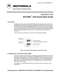
6.4 Serial Communication Interface
The serial communication interface (SCI) communicates with external devices through
an asynchronous serial bus. The SCI uses a standard non-return to zero (NRZ) transmission format. The SCI is fully compatible with other Motorola SCI systems, such as
those on M68HC11 and M68HC05 devices. Figure 6-10 is a block diagram of the SCI
transmitter. Figure 6-11 is a block diagram of the SCI receiver.
MC68332
USER’S MANUAL
QUEUED SERIAL MODULE
Rev. 15 Oct 2000
MOTOROLA
6-23
6.4.1 SCI Registers
The SCI programming model includes the QSM global and pin control registers, and
four SCI registers. There are two SCI control registers (SCCR0 and SCCR1), one status register (SCSR), and one data register (SCDR). Refer to APPENDIX D
REGISTER SUMMARY for register bit and field definitions.
6.4.1.1 Control Registers
SCCR0 contains the baud rate selection field. Baud rate must be set before the SCI is
enabled. This register can be read or written.
SCCR1 contains a number of SCI configuration parameters, including transmitter and
receiver enable bits, interrupt enable bits, and operating mode enable bits. This
register can be read or written at any time. The SCI can modify the RWU bit under certain circumstances.
Changing the value of SCI control bits during a transfer may disrupt operation. Before
changing register values, allow the SCI to complete the current transfer, then disable
the receiver and transmitter.
MC68332
USER’S MANUAL
QUEUED SERIAL MODULE
Rev. 15 Oct 2000
MOTOROLA
6-24
(WRITE-ONLY)
SCDR Tx BUFFER
TRANSMITTER
BAUD RATE
CLOCK
START
PIN BUFFER
AND CONTROL
IDLE
RAF
RDRF
TDRE
15
TC
SBK
0
SCSR STATUS REGISTER
0
TCIE
TIE
SCCR1 CONTROL REGISTER 1
RWU
RE
TE
ILIE
RIE
TCIE
TIE
WAKE
M
PE
PT
ILT
WOMS
LOOPS
TRANSMITTER
CONTROL LOGIC
15
TxD
PF
L
FE
0
OPEN DRAIN OUTPUT MODE ENABLE
1
NF
2
OR
PARITY
GENERATOR
3
FORCE PIN DIRECTION (OUT)
4
PREAMBLE—JAM 1's
5
JAM ENABLE
6
SHIFT ENABLE
SIZE 8/9
H (8) 7
TRANSFER Tx BUFFER
10 (11)-BIT Tx SHIFT REGISTER
BREAK—JAM 0's
STOP
DDRQS(D7)
TDRE
TC
INTERNAL
DATA BUS
SCI Rx
REQUESTS
SCI INTERRUPT
REQUEST
16/32 SCI TX BLOCK
Figure 6-10 SCI Transmitter Block Diagram
MC68332
USER’S MANUAL
QUEUED SERIAL MODULE
Rev. 15 Oct 2000
MOTOROLA
6-25
RxD
STOP
÷16
DATA
RECOVERY
PIN BUFFER
START
RECEIVER
BAUD RATE
CLOCK
10 (11)-BIT
Rx SHIFT REGISTER
H (8) 7
6
5
4
MSB
3
2
1
0
L
ALL ONES
PARITY
DETECT
15
SCCR1 CONTROL REGISTER 1
SBK
RWU
RE
TE
ILIE
RIE
TCIE
TIE
WAKE
M
PE
PT
ILT
WOMS
0
LOOPS
WAKE-UP
LOGIC
0
SCDR Rx BUFFER
15
SCI Tx
REQUESTS
SCSR STATUS REGISTER
PF
FE
NF
OR
IDLE
RAF
RDRF
TC
TDRE
(READ-ONLY)
0
SCI INTERRUPT
REQUEST
INTERNAL
DATA BUS
16/32 SCI RX BLOCK
Figure 6-11 SCI Receiver Block Diagram
MC68332
USER’S MANUAL
QUEUED SERIAL MODULE
Rev. 15 Oct 2000
MOTOROLA
6-26
6.4.1.2 Status Register
SCSR contains flags that show SCI operating conditions. These flags are cleared
either by SCI hardware or by reading SCSR, then reading or writing SCDR. A longword read can consecutively access both SCSR and SCDR. This action clears
receiver status flag bits that were set at the time of the read, but does not clear TDRE
or TC flags.
If an internal SCI signal for setting a status bit comes after reading the asserted status
bits, but before reading or writing SCDR, the newly set status bit is not cleared. SCSR
must be read again with the bit set, and SCDR must be read or written before the status bit is cleared.
Reading either byte of SCSR causes all 16 bits to be accessed, and any status bit
already set in either byte is cleared on a subsequent read or write of SCDR.
6.4.1.3 Data Register
SCDR contains two data registers at the same address. The receive data register
(RDR) is a read-only register that contains data received by the SCI. Data enters the
receive serial shifter and is transferred to RDR. The transmit data register (TDR) is a
write-only register that contains data to be transmitted. Data is first written to TDR,
then transferred to the transmit serial shifter, where additional format bits are added
before transmission. R[7:0]/T[7:0] contain either the first eight data bits received when
SCDR is read, or the first eight data bits to be transmitted when SCDR is written. R8/
T8 are used when the SCI is configured for 9-bit operation. When the SCI is configured
for 8-bit operation, they have no meaning or effect.
6.4.2 SCI Pins
Two unidirectional pins, TXD (transmit data) and RXD (receive data), are associated
with the SCI. TXD can be used by the SCI or for general-purpose I/O. TXD function is
controlled by PQSPA7 in the port QS pin assignment register (PQSPAR) and TE in
SCI control register 1 (SCCR1). The receive data (RXD) pin is dedicated to the SCI.
6.4.3 SCI Operation
The SCI can operate in polled or interrupt-driven mode. Status flags in SCSR reflect
SCI conditions regardless of the operating mode chosen. The TIE, TCIE, RIE, and ILIE
bits in SCCR1 enable interrupts for the conditions indicated by the TDRE, TC, RDRF,
and IDLE bits in SCSR, respectively.
6.4.3.1 Definition of Terms
• Bit-Time — The time required to transmit or receive one bit of data, which is equal
to one cycle of the baud frequency.
• Start Bit — One bit-time of logic zero that indicates the beginning of a data frame.
A start bit must begin with a one-to-zero transition and be preceded by at least
three receive time samples of logic one.
• Stop Bit— One bit-time of logic one that indicates the end of a data frame.
MC68332
USER’S MANUAL
QUEUED SERIAL MODULE
Rev. 15 Oct 2000
MOTOROLA
6-27
• Frame — A complete unit of serial information. The SCI can use 10-bit or 11-bit
frames.
• Data Frame — A start bit, a specified number of data or information bits, and at
least one stop bit.
• Idle Frame — A frame that consists of consecutive ones. An idle frame has no
start bit.
• Break Frame — A frame that consists of consecutive zeros. A break frame has
no stop bits.
6.4.3.2 Serial Formats
All data frames must have a start bit and at least one stop bit. Receiving and transmitting devices must use the same data frame format. The SCI provides hardware
support for both 10-bit and 11-bit frames. The M bit in SCCR1 specifies the number of
bits per frame.
The most common data frame format for NRZ serial interfaces is one start bit, eight
data bits (LSB first), and one stop bit; a total of 10 bits. The most common 11-bit data
frame contains one start bit, eight data bits, a parity or control bit, and one stop bit.
Ten-bit and eleven-bit frames are shown in Table 6-4.
Table 6-4 Serial Frame Formats
10-Bit Frames
Start
Data
Parity/Control
Stop
1
7
—
2
1
7
1
1
1
8
—
1
11-Bit Frames
Start
Data
Parity/Control
Stop
1
7
1
2
1
8
1
1
6.4.3.3 Baud Clock
The SCI baud rate is programmed by writing a 13-bit value to the SCBR field in SCI
control register zero (SCCR0). The baud rate is derived from the MCU system clock
by a modulus counter. Writing a value of zero to SCBR[12:0] disables the baud rate
generator. Baud rate is calculated as follows:
f sys
SCI Baud Rate = ------------------------------------------32 × SCBR[12:0]
or
f sys
SCBR[12:0] = -------------------------------------------------------------------------32 × SCI Baud Rate Desired
where SCBR[12:0] is in the range {1, 2, 3, ..., 8191}.
MC68332
USER’S MANUAL
QUEUED SERIAL MODULE
Rev. 15 Oct 2000
MOTOROLA
6-28
The SCI receiver operates asynchronously. An internal clock is necessary to synchronize with an incoming data stream. The SCI baud rate generator produces a receive
time sampling clock with a frequency 16 times that of the SCI baud rate. The SCI determines the position of bit boundaries from transitions within the received waveform, and
adjusts sampling points to the proper positions within the bit period.
6.4.3.4 Parity Checking
The PT bit in SCCR1 selects either even (PT = 0) or odd (PT = 1) parity. PT affects
received and transmitted data. The PE bit in SCCR1 determines whether parity checking is enabled (PE = 1) or disabled (PE = 0). When PE is set, the MSB of data in a
frame is used for the parity function. For transmitted data, a parity bit is generated; for
received data, the parity bit is checked. When parity checking is enabled, the PF bit in
the SCI status register (SCSR) is set if a parity error is detected.
Enabling parity affects the number of data bits in a frame, which can in turn affect
frame size. Table 6-5 shows possible data and parity formats.
Table 6-5 Effect of Parity Checking on Data Size
M
PE
Result
0
0
8 data bits
0
1
7 data bits, 1 parity bit
1
0
9 data bits
1
1
8 data bits, 1 parity bit
6.4.3.5 Transmitter Operation
The transmitter consists of a serial shifter and a parallel data register (TDR) located in
the SCI data register (SCDR). The serial shifter cannot be directly accessed by the
CPU32. The transmitter is double-buffered, which means that data can be loaded into
TDR while other data is shifted out. The TE bit in SCCR1 enables (TE = 1) and disables (TE = 0) the transmitter.
The shifter output is connected to the TXD pin while the transmitter is operating (TE =
1, or TE = 0 and transmission in progress). Wired-OR operation should be specified
when more than one transmitter is used on the same SCI bus. The WOMS bit in
SCCR1 determines whether TXD is an open-drain (wired-OR) output or a normal
CMOS output. An external pull-up resistor on TXD is necessary for wired-OR operation. WOMS controls TXD function whether the pin is used by the SCI or as a generalpurpose I/O pin.
MC68332
USER’S MANUAL
QUEUED SERIAL MODULE
Rev. 15 Oct 2000
MOTOROLA
6-29
Data to be transmitted is written to SCDR, then transferred to the serial shifter. The
transmit data register empty (TDRE) flag in SCSR shows the status of TDR. When
TDRE = 0, TDR contains data that has not been transferred to the shifter. Writing to
SCDR again overwrites the data. TDRE is set when the data in TDR is transferred to
the shifter. Before new data can be written to SCDR, however, the processor must
clear TDRE by writing to SCSR. If new data is written to SCDR without first clearing
TDRE, the data will not be transmitted.
The transmission complete (TC) flag in SCSR shows transmitter shifter state. When
TC = 0, the shifter is busy. TC is set when all shifting operations are completed. TC is
not automatically cleared. The processor must clear it by first reading SCSR while TC
is set, then writing new data to SCDR.
The state of the serial shifter is checked when the TE bit is set. If TC = 1, an idle frame
is transmitted as a preamble to the following data frame. If TC = 0, the current operation continues until the final bit in the frame is sent, then the preamble is transmitted.
The TC bit is set at the end of preamble transmission.
The SBK bit in SCCR1 is used to insert break frames in a transmission. A non-zero
integer number of break frames is transmitted while SBK is set. Break transmission
begins when SBK is set, and ends with the transmission in progress at the time either
SBK or TE is cleared. If SBK is set while a transmission is in progress, that transmission finishes normally before the break begins. To assure the minimum break time,
toggle SBK quickly to one and back to zero. The TC bit is set at the end of break transmission. After break transmission, at least one bit-time of logic level one (mark idle) is
transmitted to ensure that a subsequent start bit can be detected.
If TE remains set, after all pending idle, data and break frames are shifted out, TDRE
and TC are set and TXD is held at logic level one (mark).
When TE is cleared, the transmitter is disabled after all pending idle data, and break
frames are transmitted. The TC flag is set, and control of the TXD pin reverts to PQSPAR and DDRQS. Buffered data is not transmitted after TE is cleared. To avoid losing
data in the buffer, do not clear TE until TDRE is set.
Some serial communication systems require a mark on the TXD pin even when the
transmitter is disabled. Configure the TXD pin as an output, then write a one to PQS7.
When the transmitter releases control of the TXD pin, it will revert to driving a logic one
output.
To insert a delimiter between two messages, to place non-listening receivers in wakeup mode between transmissions, or to signal a retransmission by forcing an idle line,
clear and then set TE before data in the serial shifter has shifted out. The transmitter
finishes the transmission, then sends a preamble. After the preamble is transmitted, if
TDRE is set, the transmitter will mark idle. Otherwise, normal transmission of the next
sequence will begin.
MC68332
USER’S MANUAL
QUEUED SERIAL MODULE
Rev. 15 Oct 2000
MOTOROLA
6-30
Both TDRE and TC have associated interrupts. The interrupts are enabled by the
transmit interrupt enable (TIE) and transmission complete interrupt enable (TCIE) bits
in SCCR1. Service routines can load the last byte of data in a sequence into SCDR,
then terminate the transmission when a TDRE interrupt occurs.
6.4.3.6 Receiver Operation
The RE bit in SCCR1 enables (RE = 1) and disables (RE = 0) the receiver. The
receiver contains a receive serial shifter and a parallel receive data register (RDR)
located in the SCI data register (SCDR). The serial shifter cannot be directly accessed
by the CPU32. The receiver is double-buffered, allowing data to be held in RDR while
other data is shifted in.
Receiver bit processor logic drives a state machine that determines the logic level for
each bit-time. This state machine controls when the bit processor logic is to sample
the RXD pin and also controls when data is to be passed to the receive serial shifter.
A receive time clock is used to control sampling and synchronization. Data is shifted
into the receive serial shifter according to the most recent synchronization of the
receive time clock with the incoming data stream. From this point on, data movement
is synchronized with the MCU system clock. Operation of the receiver state machine
is detailed in the QSM Reference Manual (QSMRM/AD).
The number of bits shifted in by the receiver depends on the serial format. However,
all frames must end with at least one stop bit. When the stop bit is received, the frame
is considered to be complete, and the received data in the serial shifter is transferred
to RDR. The receiver data register flag (RDRF) is set when the data is transferred.
Noise errors, parity errors, and framing errors can be detected while a data stream is
being received. Although error conditions are detected as bits are received, the noise
flag (NF), the parity flag (PF), and the framing error (FE) flag in SCSR are not set until
data is transferred from the serial shifter to RDR.
RDRF must be cleared before the next transfer from the shifter can take place. If
RDRF is set when the shifter is full, transfers are inhibited and the overrun error (OR)
flag in SCSR is set. OR indicates that RDR needs to be serviced faster. When OR is
set, the data in RDR is preserved, but the data in the serial shifter is lost. Because
framing, noise, and parity errors are detected while data is in the serial shifter, FE, NF,
and PF cannot occur at the same time as OR.
When the CPU32 reads SCSR and SCDR in sequence, it acquires status and data,
and also clears the status flags. Reading SCSR acquires status and arms the clearing
mechanism. Reading SCDR acquires data and clears SCSR.
When RIE in SCCR1 is set, an interrupt request is generated whenever RDRF or OR
is set. Because receiver status flags are set at the same time as RDRF, they do not
have separate interrupt enables.
MC68332
USER’S MANUAL
QUEUED SERIAL MODULE
Rev. 15 Oct 2000
MOTOROLA
6-31
6.4.3.7 Idle-Line Detection
During a typical serial transmission, frames are transmitted isochronally and no idle
time occurs between frames. Even when all the data bits in a frame are logic ones, the
start bit provides one logic zero bit-time during the frame. An idle line is a sequence of
contiguous ones equal to the current frame size. Frame size is determined by the state
of the M bit in SCCR1.
The SCI receiver has both short and long idle-line detection capability. Idle-line detection is always enabled. The idle line type (ILT) bit in SCCR1 determines which type of
detection is used. When an idle line condition is detected, the IDLE flag in SCSR is set.
For short idle-line detection, the receiver bit processor counts contiguous logic one bittimes whenever they occur. Short detection provides the earliest possible recognition
of an idle line condition, because the stop bit and contiguous logic ones before and
after it are counted. For long idle-line detection, the receiver counts logic ones after the
stop bit is received. Only a complete idle frame causes the IDLE flag to be set.
In some applications, software overhead can cause a bit-time of logic level one to
occur between frames. This bit-time does not affect content, but if it occurs after a
frame of ones when short detection is enabled, the receiver flags an idle line.
When the ILIE bit in SCCR1 is set, an interrupt request is generated when the IDLE
flag is set. The flag is cleared by reading SCSR and SCDR in sequence. IDLE is not
set again until after at least one frame has been received (RDRF = 1). This prevents
an extended idle interval from causing more than one interrupt.
6.4.3.8 Receiver Wake-up
The receiver wake-up function allows a transmitting device to direct a transmission to
a single receiver or to a group of receivers by sending an address frame at the start of
a message. Hardware activates each receiver in a system under certain conditions.
Resident software must process address information and enable or disable receiver
operation.
A receiver is placed in wake-up mode by setting the RWU bit in SCCR1. While RWU
is set, receiver status flags and interrupts are disabled. Although the CPU32 can clear
RWU, it is normally cleared by hardware during wake-up.
The WAKE bit in SCCR1 determines which type of wake-up is used. When WAKE =
0, idle-line wake-up is selected. When WAKE = 1, address-mark wake-up is selected.
Both types require a software-based device addressing and recognition scheme.
Idle-line wake-up allows a receiver to sleep until an idle line is detected. When an idleline is detected, the receiver clears RWU and wakes up. The receiver waits for the first
frame of the next transmission. The byte is received normally, transferred to RDR, and
the RDRF flag is set. If software does not recognize the address, it can set RWU and
put the receiver back to sleep. For idle-line wake-up to work, there must be a minimum
of one frame of idle line between transmissions. There must be no idle time between
frames within a transmission.
MC68332
USER’S MANUAL
QUEUED SERIAL MODULE
Rev. 15 Oct 2000
MOTOROLA
6-32
Address-mark wake-up uses a special frame format to wake up the receiver. When the
MSB of an address-mark frame is set, that frame contains address information. The
first frame of each transmission must be an address frame. When the MSB of a frame
is set, the receiver clears RWU and wakes up. The byte is received normally, transferred to the RDR, and the RDRF flag is set. If software does not recognize the
address, it can set RWU and put the receiver back to sleep. Address-mark wake-up
allows idle time between frames and eliminates idle time between transmissions. However, there is a loss of efficiency because of an additional bit-time per frame.
6.4.3.9 Internal Loop Mode
The LOOPS bit in SCCR1 controls a feedback path in the data serial shifter. When
LOOPS is set, the SCI transmitter output is fed back into the receive serial shifter. TXD
is asserted (idle line). Both transmitter and receiver must be enabled before entering
loop mode.
MC68332
USER’S MANUAL
QUEUED SERIAL MODULE
Rev. 15 Oct 2000
MOTOROLA
6-33
MC68332
USER’S MANUAL
QUEUED SERIAL MODULE
Rev. 15 Oct 2000
MOTOROLA
6-34