1
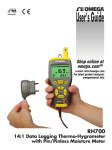
WDR
W HISTLE D ETECTOR R ELAY
U SER M ANUAL
M ICRO -A IDE
R AIL S IGNAL P RODUCTS
E VENT R ECORDERS
S PEED M ONITORS
C URRENT S ENSORS
I SOLATED M ODEMS
B ATTERY M ONITORS
V OLTAGE M ONITORS
L IGHT O UT D ETECTORS
C LOCK S YNCHRONIZERS
W HISTLE D ETECTORS
L OCAL C ONTROL P ANELS
C USTOM E NGINEERING
MICRO-AIDE CORPORATION
Tel: 626-915-5502
Fax: 626-331-9484
685 Arrow Grand Circle Covina, CA 91722
E-mail: [email protected]
WDR
W HISTLE D ETECTOR R ELAY
U SER M ANUAL
The WDR can be used to avoid potential hazards at crossings during
lengthy train delays. A whistle blast by the engineer is detected by
the WDR and used to reactivate the nearby crossing lights and gate.
Description
Installation
This document is intended to provide a detailed
description of the use and operation of the
MICRO-AIDE WDR Whistle Detector Relay.
The WDR can be mounted on a shelf or back board.
It may be oriented either horizontally or vertically.
Four mounting holes at the base of the unit can be
used to secure the WDR.
The WDR is a unique audio device that allows a train
engineer to activate a nearby crossing from a position
within the train’s cab. A loud blast from the train’s
whistle is automatically detected by the WDR. If the
audio level and duration are sufficient the WDR will
operate its internal relay. The relay includes two sets
of contacts. Typically one set of contacts is wired to
the control circuits of the crossing equipment.
A detachable connector is used to simplify the wiring
procedure. Wire gauges from 12 to 22 AWG may be
used. Each conductor is secured by tightening the set
screw associated with each connector terminal. The
unit’s silkscreening provides a clear indication of the
connections to be made.
The power source is connected to the terminals
labeled “B” and “N”. Dual power terminals are
provided. The design of the WDR is fully
compatible with a switched on/off power source.
Consequently, the user may wish to connect the
WDR to the power source through the normally open
contacts of a relay. If the relay closes its contacts
only when a train is present the WDR will be
prevented from activating the crossing when a train is
not at the station. This method of installation is
strictly optional. If properly adjusted, the WDR will
not falsely activate the crossing. However, this
installation option will provide an additional measure
of fail safe operation.
The most common application requiring a WDR
involves commuter trains stopped at a station. A
lengthy delay of the train at the station may cause a
nearby crossing to revert to its idle position (i.e.,
arms up, lights off). This may result in a potentially
unsafe situation when the train is prepared to pull
away from the station. However, proper use of the
WDR can insure that the crossing will be activated
prior to the train’s departure.
The WDR is designed to be used in typical railroad
environments. Its operating temperature range is
-40°C to +72°C. Its rugged aluminum chassis and
circuit board construction allow it to withstand harsh
environmental conditions. The WDR’s internal
printed circuit board includes a conformal coating.
Its small footprint (4.2" by 4.7") allows it to be
mounted in any convenient location.
The wire pair from the external speaker or
microphone should be connected to the terminals
labeled “Mic.”. The WDR can be used with any
8 Ohm outdoor speaker or microphone.
MICRO-AIDE does not supply a speaker or
microphone with the WDR. The wires to the speaker
should be twisted and kept to less than 100 ft. in
length. It is best not to run the speaker wires
alongside any power or high induction cables.
The WDR can be powered by any source in the range
from 8 to 36 Vdc. Its current draw is than 70 mA.
Figure 1 provides a three-sided view of the WDR.
The last page of this document lists detailed
specifications.
2
Operation of the WDR is fully automatic once the
sensitivity level and delay time are selected. No
further adjustments or servicing is required.
The WDR includes a pair of normally open, normally
closed and common relay contacts. The contacts are
labeled “N.O.”, “N.C.” and “Com.”, respectively.
Both sets of contacts operate simultaneously. The
crossing control circuit should be wired to one set of
contacts. As an option, the spare set of contacts can
be used to control an external lamp, or wired to a data
logging device such as a MICRO-AIDE CWR-22xt
Event Recorder.
Maintenance and
Trouble-shooting
The WDR is designed to be completely maintenance
free. It contains no consumable materials or
serviceable components. There are no fuses or other
replaceable parts internal to the unit.
Setup and Operation
The WDR provides adjustable control of its audio
sensitivity and detection time settings. The two
adjustment controls are labeled “Level Adj.” and
“Delay Adj.”, respectively. Additionally, inside the
WDR is a jumper setting that selects either high gain
or low gain. The jumper setting is labeled “JP1”. If
the jumper clip is off (default factory setting), the
high gain setting is selected. If the jumper clip is on,
the low gain setting is selected. The high gain setting
adds 6 dB of gain relative to the low setting.
The WDR is not prone to drift or stability problems.
Consequently, it will not require periodic adjustments
after its initial setup. However, the external speaker
or microphone may over time lose some efficiency.
For this reason, MICRO-AIDE recommends that the
operation of each WDR installation be inspected at
least once a year.
All rail signal products manufactured by
MICRO-AIDE are protected by a five-year limited
warranty. Telephone numbers and a shipping address
are listed below.
The WDR can be properly adjusted by using the
following procedure. Apply power to the WDR. The
green “Power” LED should be illuminated. While
the train whistle can be heard adjust the “Level Adj.”
potentiometer until the “Sound” LED illuminates
consistently. The “Sound” LED should turn off
immediately after the whistle stops. Rotate the
“Delay Adj.” potentiometer for the desired detection
time. The detection time is measured from the start
of the whistle blast to the time the “Relay” LED
illuminates. The detection time can be adjusted in
the range from approximately .5 to 10 seconds.
MICRO-AIDE CORPORATION
685 Arrow Grand Circle
Covina, CA 91722
Tel: 626-915-5502
Fax: 626-331-9484
E-mail: [email protected]
3
Figure 1 – Three-sided view
4
4.25"
WDR
Relay
Delay
Adj.
Sound
Level
Adj.
4.2"
Mic.
Power
B
B
N
N
2.0"
M ICRO -A IDE
N.O.
N.C.
Com. Relay
N.O.
N.C.
Com.
1.4"
Detachable Connector
Pot. Adjustments (2)
LED Indicators (3)
3/16" Dia.
Mounting Holes (4)
4.7"
WDR
W HISTLE D ETECTOR R ELAY
S PECIFICATIONS
Physical
Size
Length: 4.7"
Width: 4.2"
Height: 1.4"
Weight
Less than 8 oz.
Environmental
Storage
Temperature: -40°C to 85°C
Humidity: 0% to 95%, noncondensing
Operating
Temperature: -40°C to 72°C
Humidity: 0% to 95%, noncondensing
Mounting
Can be secured to any flat
surface
Cover includes mounting holes
Construction
Chassis
Fully enclosed, anodized
aluminum
Electrical
Components mounted on
internal PCB
Power
Voltage
8 to 36 Vdc
Current
70 mA maximum
Isolation
LED Indicators
Relay Contacts
Minimum 3000 Vdc to all other
points
MIC Inputs
Minimum 1500 Vdc to all other
points
MIC Input
Transformer coupled, designed
for 8 Ohm source impedance
Microphone or outdoor speaker
can be used as the input source
Audio Sensitivity
Minimum 250 mVrms at MIC
inputs, with maximum gain
setting
Frequency Range
60 to 1000 Hz
Not frequency discriminatory
Detection Time
Adjustable from .5 to
10 seconds
Connector
Detachable, screw-down with
12 terminals, 12 to 22 AWG
Terminals 1 & 2: B, battery
positive
Terminals 3 & 4: N, battery
negative
Terminals 5 & 6: microphone
Terminals 7 & 10: normally
open relay contact
Terminals 8 & 11: normally
closed relay contact
Terminals 9 & 12: relay
common
5
Power: green
Sound: green
Relay: green
Controls
External
Potentiometer for adjusting
audio level, single turn
Potentiometer for adjusting
detection time, single turn
Internal
Jumper for setting audio gain,
26 dB (low) or 32 dB (high)
Output Relay
Operation
Operates when audio level and
duration exceed their respective
limit values
Type
Non-latching mechanical, dual
SPDT contacts
Contacts
Rated Load: 1 A at 24 Vdc, .5 A
at 125 Vac
Minimum Load: 1 mA at 5 Vdc
Maximum Operating Voltage:
60 Vdc, 125 Vac
Maximum Switching Capacity:
62.5 VA, 30 W
Service Life: 5 million
mechanical (minimum), 1 million
electrical (typical)