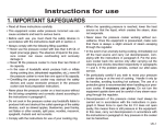
1
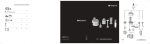
This document is to be used in conjunction with the original manufacturer’s manual.
The symbols correspond with the numbered drawings of the original manual.
GB
06/2007
Contents
Introduction
Installation
Use, safety
Cleaning, hygiene and storage
Fault finding
Maintenance
Conformity with regulations
1
1
2
4
4
5
6
Introduction
The User Manual contains useful information for the user on
how to work correctly and in complete safety, and is designed
to make it easier to use the machine (called «machine» or
«appliance» below).
What follows is in no case intended to be a long list of warnings
and constraints, but rather a series of instructions meant to
improve the service provided by the machine in every respect,
and particularly to avoid a series of injuries or damage to equipment that might result from inappropriate procedures for use
and management.
It is essential that all the people responsible for transporting,
installing, commissioning, using, maintaining, repairing or dismantling the machine should consult this manual and read it carefully
before proceeding with the various operations, in order to avoid
any incorrect or inappropriate handling that might be result in
damage to the machine or put people’s safety at risk.
It is just as important that the Manual should always be available
to the operator and it should be kept carefully where the machine
is used ready for easy and immediate consultation in case of any
doubt, or in any case, whenever the need arises.
If after reading the Manual, there are still any doubts concerning
how to use the machine, please do not hesitate to contact the
Manufacturer or approved After Sales Service provider, who
is constantly available to ensure quick and careful service for
improved machine operation and optimum efficiency.
Note that the safety, hygiene and environmental protection standards currently applicable in the country where the machine is
installed must always be applied during all phases of machine
operation. Consequently it is the user’s responsibility to ensure
that the machine is operated and used solely under the optimum
safety conditions laid down for people, animals and property.
Introduction
1.1 DESCRIPTION
The Mini Green provides the fresh cut in the kitchen, for shredding, slicing and grating (for the preparation of raw and cooked
vegetables, fruits and cheeses).
- Thanks to its adapted rotation speed, a quality cut is obtained
every time.
- Always ready and compact, it provides a rapid and economical
solution for the preparation of fresh food for catering.
Mini Green features :
1) The motor base
A Feet
1.1
B Casing
C Body
D Drive spindle
E Start - stop buttons
On button (green) marked ON
Off button (red) marked OFF
2) The fresh cut equipment
F
Feed hopper assembly
G Feed arm
H Small feed hopper
I
Pusher
J
Large hopper
K 4 basic discs
L
Ejector
Installation
2.1 DIMENSIONS - WEIGHT (for information only)
• Gross weight when packaged: 13 kg/ Net weight 12 kg
• Dimensions of Mini Green :
2.1
• Dimensions of packaging in mm :
L : 410
l : 260
h : 440
2.2 LOCATION AND LAYOUT
• The Mini Green is to be fitted on a table of between 700 and
900 mm in height. Its 4 feet ensure perfect stability.
• Account has been taken of ergonomical factors to allow the
Mini Green to be used in any position, to suit the conditions
imposed by the installation.
• Fitted on a table, it can take a standard receiving bowl of
maximum height of 175 mm. If the bowl is higher than this, place
the machine on the edge of the table to discharge the products
above the receiving bowl.
• Reception of the vegetables :
2.2
A On the left
C In front
B On the right
D At the back
1
MIG GB 06 07
2.3 ELECTRICAL CONNECTION
ATTENTION !!
Connection to the electrical power supply must be done according to proper professional practice by a qualified and authorised
person (see current standards and legislation in the country of installation).
If an adapter is used on the socket, a check must be made that the electrical characteristics of this adapter are not lower than
those of the machine.
Do not use multiple plugs
The AC power supply to the machine must comply with the following conditions;
- Maximum voltage variation: ±5%
- Maximum frequency variation: ±1% on a continuous basis, ± 2% over short periods
ATTENTION: the electrical installation must comply (for design, creation and maintenance) with the legal and standard
requirements in the country where used.
- Before connecting the machine to the electrical power supply, check that the voltage of the electrical system is the same as
that marked on the rating plate and the label on the power cable.
- The machine’s electrical power supply must be protected against voltage surges (short-circuits and excess voltages) by
using fuses or thermal relays of the appropriate gauge relative to the place of installation and machine specifications - see the
specifications shown in column F of figure 2.3a
ATTENTION: Concerning protection against indirect contact (depending on the type of power supply provided and
connection of the exposed conductive parts to the equipotential protection circuit), refer to point 6.3.3 of EN 60204-1 (IEC
60204-1) with the use of protection devices for automatic shut-off of power in the event of an insulation fault with a TN or
TT system, or, for the IT system, with the use of a permanent insulation or differentials controller for automatic shut-off.
The requirements of IEC 60364-4-41, 413.1 must apply for this protection.
For example: in a TT system, a differential circuit breaker must be installed upline of the power supply, with a suitable
power cut-off (e.g.: 30 mA) on the earthing installation for the place where it is planned to install the machine.
ATTENTION: Failure to comply with these instructions means the customer runs the risk of machine failure and/or accidents due to direct or indirect contacts.
• The machine is connected to a single phase supply by means
of a moulded 2 pin + earth plug 10/16A rating.
• Before connecting the machine to the electrical power supply,
check that the voltage of the electrical system is the same as that
marked on the rating plate and the label on the power cable.
• The machine must be protected by a differential circuit breaker
and a 16 A fuse.
To PAT test the Electrolux Range of Food Preparation Equipment,
the PCB board needs to be disconnected before any test is done.
This is due to the fact that the boards are fitted with a grounding
diode that can give incorrect result during such a test. Also on
a standard appliance a flash test of 25 amps and up to 3000v is
used but, as you would expect, to use this on equipment, which
has a printed circuit, board would be quite destructive to that
board. We would recommend the use of a PAT tester approved
for computer systems which use a lower rate of amps.
The machine must be earthed
The appliance is perfectly safe and is CE certificated. There are
two ways to get overcome this problem.
• Motor characteristics :
A Number of phases (1 single phase)
B Nominal voltage (Volts)
C Frequency (Hertz)
D Nominal power (Watts)
E Nominal current (Amperes)
F Size of fuse for protecting the electrical line (Amperes)
G Indicative electrical consumption (Kwh)
· Disconnect the board as instructed and test using test for
PC’s,
· Or install the mixer on a fused spur (no plug) as this takes it
away from being a portable appliance and the PAT test is then
not needed.
Use, safety
ATTENTION !!
Machine storage: -25°C to +50°C
Ambient temperature during operation: +4°C to +40°C
Clean the machine properly prior to its first use
This machine is for professional use and must be used by staff trained to use, clean and maintain it, in terms or reliability and
safety.
Use the machine in adequately lit premises (See applicable technical standard for the country of use. In Europe, refer to standard
EN 12464-1)
When handling the machine, always check that the parts taken hold of are not mobile elements: risk of dropping and injury to
the lower limbs.
Uncontrolled closure of the lid or ram press involves a risk of crushing the fingers.
Never put a hand in the ejection area while the machine is in operation; risk of injury. It is strictly forbidden to put the safety systems
out of action or modify them: Risk of permanent injury!!!!
Check that the safety devices operate correctly each time before using (see paragraph on «safety system adjustments»).
Never put a hand, a hard or frozen object in the appliance
For health and safety reasons, always use a washable or disposable strong head covering that covers the hair completely.
ATTENTION: All operations, whether using, cleaning or maintenance, present risks of cuts; never force and always keep
hands a reasonable distance from cutting edges.
Always use appropriate protective equipment when carrying out these operations.
The machine is not designed for use in explosive atmospheres.
MIG GB 06 07
2
3.1 USER SAFETY IS ENSURED BY :
- Respecting the instructions of this manual for the use, cleaning
and maintenance of the machine.
- The braked stoppage of the motor when the feed arm is opened so that there is no risk when loading.
- The motor not starting if the hopper assembly is missing.
- The size of the small feed hopper for long vegetables
- The absence of risk of access via the discharge chute due to
the design of the ejector and the discs.
RESIDUAL RISKS
The machine presents the following residual risks;
• If a hand is placed in the area where the products are discharged, it may be crushed or trapped by the rotating parts of
the machine.
3.2 SET OF DISCS
Basic discs supplied with the machine: TD2 - TD3 - RD2 - ED2
• RD Grating discs : grating from dia. 2 to dia. 7 mm
3.2b
3.2a
- Vegetables : carrots, grated celery, beetroots, horseradishes,
etc.
- Other : gruyere, mozzarella, walnuts, almonds, breadcrumbs,
chocolate, etc.
• TD slicing discs : straight cuts from 2 to 7 mm.
• WD slicing discs : crinkle cuts of 2 mm.
- Vegetables : potatoes, carrots, aubergines, beetroot, celery,
red and white cabbages, mushrooms, cucumbers, courgettes,
chicory, fennel, onions, leeks, radishes, etc
3.2c
• ED shredding discs : for shredding
- Thin 2 x 2 mm : doorstep potatoes, celery, carrots.
- Medium 3 x 3 mm : matchstick potatoes, carrots, etc.
- Fruits : almonds, bananas, lemons, oranges, apples, etc.
3.3 USE OF THE FRESH CUT EQUIPMENT
• The Mini Green is supplied with its feed hopper assembly and
ejector already fitted.
- Turn the hopper assembly in a clockwise direction to loosen
from the motor base and remove the ejector.
• The hopper assembly by positioning it above the motor base,
with the locks opposite the slots and the handle of the feed arm
on the same side as the electrical controls, then lower it down
as far as it will go.
Before use, always check the cleanliness of the cutting chamber,
the drive spindle, the ejector and the disc.
To equip the machine, fit :
• The ejector onto the lower flat of the drive spindle and check
that it is correctly seated.
3.3a
- Turn it anticlockwise
to lock it up against its stop. The
external profile should match that of the body.
• The chosen disc (see set of discs § 3.2) on the upper flat of the
drive spindle and check that it is correctly seated.
3.3b
Tip : to remove the ejector easily, put your thumb in the middle
and fingers below on the discharge side.
3.3d
- Check that the lever can be moved easily.
3.3c
• To dismantle, follow the instructions in reverse order.
3.4 CHOICE AND FUNCTIONS OF THE FEED HOPPERS
1) The large feed hopper with the feed arm.
A Slicing
B Shredding
- Passage for large sized products
(130 x 60 mm maximum).
2) The small feed hopper with removable feed pusher
3.4a
• For slicing long products (carrots, chicory, cucumbers, leeks,
etc.), the opening is dia. 52 mm maximum.
3.4c
C Grating
• To slice, always insert long products tip first.
• Manual loading is carried out by inserting the products vertically into the small hopper one at a time or in handfuls.
3.4b
• Manual loading is carried out by inserting the products one at
a time or in handfuls into the large hopper, taking care to position
them correctly in order to avoid wastage. Pack fragile products
(tomatoes, citrus fruits) against the side.
• Tips for avoiding :
- angled and irregular cuts: place thin products in ''head first''
- blockages, cut off the ends of the vegetables.
3.5 USE OF THE LARGE FEED HOPPER AND THE FEED ARM
Mini Green will only operate if the hopper assembly is correctly
locked onto the motor base, otherwise the safety device is engaged and the machine will not start (see § 3.1).
3.5c
- When the feed arm is lowered, the motor will start up again
automatically.
- Using the feed arm, insert the products into the feed hopper
until it reaches its lower stop.
- Raise the feed arm and begin a new cycle.
- When the work has been completed, press the red STOP
button.
3.5a
- Leave the feed pusher inside of the small feed hopper to
prevent the products from coming back out.
- Press the START button.
- Lift up the feed arm with one hand.
3.5d
3.5b
Note : The force applied to the feed arm depends on :
- the product being used (soft product = less force)
- the cutter chosen (a grater requires more effort than a slicing
disc).
- As soon as the feed arm is clear of the large feed hopper, the
motor stops immediately, thus allowing the products to be
changed in complete safety.
3
MIG GB 06 07
3.6 USE OF THE SMALL FEED HOPPER AND THE FEED PUSHER
- Leave the feed arm in its lower position.
- Press the START button to start operation.
- Raise the feed pusher and insert the products with the
other.
- Push the products using the feed pusher and start a new cycle.
3.6
- When the work has been completed, press the STOP button.
Never insert your hand or a hard object in the feed hopper
when the machine is in operation
Cleaning, hygiene and storage
ATTENTION !!
Before dismantling any part, disconnect the appliance from the power supply.
Before using any cleaning product, be sure to read the instruction and safety instructions accompanying the product and use
appropriate protective equipment.
Do not clean the machine with a pressure cleaner
4.1 IN BETWEEN USE
- Remove the removable elements (hopper assembly, pusher,
disc, ejector of the fresh cut equipment), wash in hot water,
rinse and dry.
- Clean the cutting chamber using a clean, damp sponge.
4.2 AFTER USE
- Refer to § 4.1.
- Clean the removable parts in hot water and detergent - degreaser - disinfectant compatible with the equipment.
- Rinse in clean water and leave to dry.
- Clean the cutting chamber using a damp sponge and a
detergent - disinfectant then rinse.
4.3 STORAGE
Note : Do not clean the plastic parts in a dishwasher
- Check that the cleaning products used are compatible with
the materials of the elements (plastic, stainless steel).
- Do not use abrasive detergents which scratch the surfaces, or
chlorine based products which can cause the plastic to crack
.
4.3
- After cleaning, carefully store all of the cutting equipment in
the storage cupboard fixed to the wall.
Fault finding
5.1 THE MACHINE WILL NOT START, CHECK THAT :
• The machine is plugged in,
• The ''fresh cut'' equipment is locked in the correct position,
• The electrical power supply to the socket is correct,
• The feed arm is in the feed hopper.
5.2 ABNORMAL NOISES :
• Stop the machine.
• Dismantle, clean if necessary and refit.
• Check that the rotating parts are fitted correctly (disc, ejector).
5.3 WORK QUALITY
- Before carrying out any work, stop the machine.
- The direction of rotation (anticlockwise
viewed from
above)
- The choice of disc used (see § 3.2)
- The condition of the cutting equipment.
- The choice of the feed hopper.
- The way that the products are in the feed hopper (see §
3.4).
If the problem persists, contact the service
department of your local dealer.
If the products have not been cleared properly, check that :
- The ejector is fitted correctly,
- The products in the receiving bowl are not blocking the outlet,
- there is not an accumulation of products in the cutting chamber.
If the quality of the cut is not satisfactory, check :
MIG GB 06 07
4
Maintenance
ATTENTION !!
Before dismantling any part, disconnect the appliance from the power supply.
Maintenance may only be carried out by a qualified, trained and authorised person
6.1 ADJUSTMENT OF THE SAFETY DEVICES
- when the hopper assembly is unlocked.
• Check that the safety devices are operating correctly on a regular
basis. The motor should stop within less than 2 seconds :
• If either of the two safety devices does not work :
- Do not use the machine.
- Have it adjusted by the service department of your local dealer.
6.1
- when the feed arm is lifted, the gap F should be 30 mm maximum from the edge of the feed hopper.
6.2 ELECTRICAL COMPONENTS
6.2
See electrical diagram at back of manual.
• Identification of the components.
• Access to electrical components.
- Unplug the machine.
O
:
Stop button
I
:
Start button
S1
:
Feed hopper assembly safety device
• The capacitors may retain an electrical charge. To avoid taking
any risks when carrying out work, we recommend discharging
them by connecting their terminals with an insulated conductor
(e.g. a screwdriver).
S5
:
Feed arm safety device
B
:
Terminal block
M
:
Single phase motor
• Identification of the colours of the wires.
- Power circuit : black
- Control circuit :
red
- Motor
: (G) Orange- (F) black- (A) red- (E) blue(H) Violet
- Phase
: L
- Neutral
: N
- Earth
: B/C green-yellow.
- Control cable : (J) Brown- (I) grey - (K) pink- (E) blue - (D)
Kl
:
Start-up relay
CP
:
Permanent condenser
CD/F
:
Start-up - braking condenser
CPu
:
Power board
Residual voltage at the capacitor terminals.
white
6.3 ADDRESS FOR SERVICE REQUIREMENTS
• We advise you to contact the dealer who sold you the machine.
Dealer’s stamp
For any information or orders for spare parts, specify
the type of machine, its serial number and the electrical
characteristics.
• The manufacturer reserves the right to modify and make
improvements to the products without giving prior warning.
Date of purchase : ...............................................
5
MIG GB 06 07
Conformity regulations
The machine has been designed and manufactured in conformity with :
- The machine directive 2006/42 EEC,
- The directive CEM 2004/108EEC.
- 2006/95/EEC: Low Voltage Directive
- 2002/95/EC: Equipment recycling directive
2002/96/CEE « WEEE »
The symbol «
» on the product indicates that this product
may not be treated as household waste. Instead it shall be
handed over to the applicable collection point for the recycling
of electrical and electronic equipment. By ensuring this product
is disposed of correctly, you will help prevent potential negative
consequences for the environment and human health, which
could otherwise be caused by inappropriate waste handling
of this product. For more detailed information about recycling
of this product, please contact the sales agent or dealer for
your product, your after-sales service, or the appropriate waste
disposal service.
2006/12/CEE“Waste”
The machine is designed so that it does not contribute, or as
little as possible, to increasing the quantity or harmfulness of the
waste and the risks of pollution.
Make sure to observe the recycling conditions.
94/62/CEE“Packaging and packaging waste”
The packaging for the machine is designed so that it does not
contribute, or as little as possible to increasing the quantity or
harmfulness of the waste and the risks of pollution.
Make sure to eliminate the various parts of the packaging in
appropriate recycling centres.
- To the European standards :
EN 60 204-1-2006 electrical equipment of machines,
EN 1678-1998 vegetable cutters, integrated safety devices.
MIG GB 06 07
This conformity is certified by :
- The CE conformity mark, attached to the machine,
- The corresponding CE declaration of conformity, associated
with the warranty,
- This instruction manual, which must be given to the operator.
Acoustic characteristics :
- The acoustic pressure level measured in conformity with the
EN ISO 3743.1-EN ISO 3744 = 71 dBA.
Protection indices as per the EN 60529-2000 standard :
- IP55 electrical controls
- IP34 overall machine
Integrated safety measures:
- The machine has been designed and manufactured in
compliance with the regulations and standards stated
above.
- Before using the machine, the operator must be trained to use
the machine and informed of any possible residual risks.
Food hygiene:
The machine is made from materials that conform to the following
regulations and standards:
- Directive 1935/2004/CEE: materials and objects in contact
with foodstuffs,
- Standards EN 601-2004: cast aluminium alloys in contact with
foodstuffs.
- Directive EN 1672-2 : Prescriptions relating to hygiene
The surfaces of the food processing area are smooth and easy
to clean. Use detergents that are approved for food hygiene and
observe the instructions for their use.
6