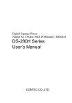
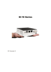
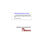
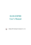
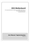
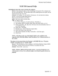
1
Digital Signage Player AMD T56N 1.65GHz, SSD, POSReady7, DVI-I DS-080D Series User’s Manual CONTEC CO.,LTD. Check Your Package Thank you for purchasing the CONTEC product. The product consists of the items listed below. Check, with the following list, that your package is complete. If you discover damaged or missing items, contact your retailer. Product Configuration List DS-080D-DC6413 Name Pcs. Product guide 1 1 1 1 Warranty Certificate 1 POSReady7 End User License Agreement 1 Setup Manual 1 The main body AC adapter AC cable *1 Serial number label 1 GHOST End User License Agreement 1 Preinstalled OS Recovery Procedures 1 Recovery Media 1 *1 Do not use this AC power cable with any devices except for an attached AC adaptor. Product Configuration Image * See the Product Configuration List to check if all the components are included for the specified number of units. DS-080D Series User’s Manual i Copyright Copyright 2012 CONTEC CO., LTD. ALL RIGHTS RESERVED. No part of this document may be copied or reproduced in any form by any means without prior written consent of CONTEC CO., LTD. CONTEC CO., LTD. makes no commitment to update or keep current the information contained in this document. The information in this document is subject to change without notice. All relevant issues have been considered in the preparation of this document. Should you notice an omission or any questionable item in this document, please feel free to notify CONTEC CO., LTD. Regardless of the foregoing statement, CONTEC assumes no responsibility for any errors that may appear in this document or for results obtained by the user as a result of using this product. Trademarks AMD and ATI are registered trademarks of AMD Corporation. MS, Microsoft and Windows are trademarks of Microsoft Corporation. AMI are registered trademarks of AMI Software International, Inc. Other brand and product names are trademarks of their respective holder. ii DS-080D Series User’s Manual Table of Contents Check your package ................................................................................................................................. i Copyright .................................................................................................................................................ii Trademarks ..............................................................................................................................................ii Table of Contents ...................................................................................................................................iii 1. INTRODUCTION 1 About the Product ................................................................................................................................... 1 Features............................................................................................................................................. 1 Supported OS ................................................................................................................................... 1 Customer Support.................................................................................................................................... 2 Web Site ........................................................................................................................................... 2 Limited One-Year Warranty ................................................................................................................... 2 How to Obtain Service............................................................................................................................ 2 Liability ................................................................................................................................................... 2 Safety Precautions ................................................................................................................................... 3 Safety Information ........................................................................................................................... 3 Caution on the DS-080D Series ...................................................................................................... 3 2. SYSTEM REFERENCE 5 Specification ............................................................................................................................................ 5 Physical Dimensions ............................................................................................................................... 6 3. HARDWARE SETUP 7 Before Using the Product for the First Time.......................................................................................... 7 Hardware Setup ....................................................................................................................................... 8 Installation Requirements ................................................................................................................ 8 4. EACH COMPONENT FUNCTION 9 Component Name.................................................................................................................................... 9 Front View........................................................................................................................................ 9 Component Function ............................................................................................................................. 10 DC Power Input Connector: DC-IN .............................................................................................. 10 Display Interface: DVI-I................................................................................................................ 10 Giga bit-Ethernet: LAN A – B ...................................................................................................... 11 Serial Port Interface : SERIAL A.................................................................................................. 11 USB Ports ....................................................................................................................................... 12 Line out Interface: AUDIO............................................................................................................ 12 DS-080D Series User’s Manual iii 5. BIOS SETUP 13 Introduction............................................................................................................................................13 Starting Setup.........................................................................................................................................13 Using Setup............................................................................................................................................13 Getting Help....................................................................................................................................13 In Case of Problems........................................................................................................................14 A Final Note About Setup..............................................................................................................14 Main .......................................................................................................................................................15 Advanced ...............................................................................................................................................16 ACPI Settings ........................................................................................................................................17 CPU Configuration .........................................................................................................................18 IDE Configuration ..........................................................................................................................19 USB Configuration .........................................................................................................................20 Super IO Configuration .........................................................................................................................21 H/W Monitor..........................................................................................................................................22 Chipset ...................................................................................................................................................23 North Bridge ..........................................................................................................................................24 GFX Configuration................................................................................................................................26 Memory Configuration ..........................................................................................................................27 South Bridge ..........................................................................................................................................28 SB SATA Configuration .......................................................................................................................29 SB USB Configuration ..........................................................................................................................30 SB GPP Port Configuration...................................................................................................................31 SB HD Azalia Configuration ................................................................................................................32 Boot ........................................................................................................................................................33 Security ..................................................................................................................................................34 Save & Exit Settings..............................................................................................................................35 6. APPENDIX 37 Battery ....................................................................................................................................................37 iv DS-080D Series User’s Manual 1. Introduction 1. Introduction About the Product This is STB for signage, working with AMD G-Series Dual-Core APU (Accelerated Processing Unit) T56N 1.65GHz. CPU with enhanced graphics performance helps Full-HD movie to be played smoothly with DVI-I interface. SSD can be installed as storage. The body is so compact and supports SATA interface which can transport data at high speed. It enables you to read high-quality movie, store so big data and transport data at high bit rate. DS Series are the products assumed to be used at ordinary environment and market as "Digital Signage".Operating environment condition, supply period, maintenance period and other conditions are different from ones of our industrial products (IPC Series, BOX-PC, PT-Series and others).For details, please consult our retailer. Features Integrated processor with CPU and GPU This product is equipped with AMD G-series Dual-core APU T56N (1.65GHz) that is built-in GPU. - Discrete GPU-quality graphic processing This product has APU that is equipped with GPU (Radeon HD6320) that features discrete GPU-quality. It supports DirectX 11 and OpenGL 4, and has built-in UVD3 (Unified Video Decoder) - Fanless and compact design This fanless design is achieved with energy-saving and compact design. - Major types of peripherals are supported with rich interfaces It has a variety of extended interface such as DVI-I, 1000BASE-T x1, USB2.0 x 2, serial (RS-232C). So it can be used for various purposes. - Pre-installed Windows Embedded POSReady 7 The OS, Windows Embedded POSReady 7 which is perfect for digital signage use, is pre-installed. There are many functions on this product. Such as write filters (EWF: Enhanced Write Filter and FBWF: File-Based Write Filter) and Microsoft Office Viewer that is a file browser for Word, Excel and PowerPoint. - Kinect for Windows Runtime (Pre-installed model) The installed OS is already equipped with a Runtime module which is required on OS side to trip Kinect for Windows sensor.You can use this product as an application controller which is equipped with NUI (Natural User Interface ) that features a control with voice or gestures. Supported OS - Windows Embedded POSReady7 DS-080D Series User’s Manual 1 1. Introduction Customer Support CONTEC provides the following support services for you to use CONTEC products more efficiently and comfortably. Web Site Japanese English Chinese http://www.contec.co.jp/ http://www.contec.com/ http://www.contec.com.cn/ Latest product information CONTEC provides up-to-date information on products. CONTEC also provides product manuals and various technical documents in the PDF. Free download You can download updated driver software and differential files as well as sample programs available in several languages. Note! For product information Contact your retailer if you have any technical question about a CONTEC product or need its price, delivery time, or estimate information. Limited One-Year Warranty CONTEC products are warranted by CONTEC CO., LTD. to be free from defects in material and workmanship for up to one year from the date of purchase by the original purchaser. Repair will be free of charge only when this device is returned freight prepaid with a copy of the original invoice and a Return Merchandise Authorization to the distributor or the CONTEC group office, from which it was purchased. This warranty is not applicable for scratches or normal wear, but only for the electronic circuitry and original products. The warranty is not applicable if the device has been tampered with or damaged through abuse, mistreatment, neglect, or unreasonable use, or if the original invoice is not included, in which case repairs will be considered beyond the warranty policy. How to Obtain Service For replacement or repair, return the device freight prepaid, with a copy of the original invoice. Please obtain a Return Merchandise Authorization number (RMA) from the CONTEC group office where you purchased before returning any product. * No product will be accepted by CONTEC group without the RMA number. Liability The obligation of the warrantor is solely to repair or replace the product. In no event will the warrantor be liable for any incidental or consequential damages due to such defect or consequences that arise from inexperienced usage, misuse, or malfunction of this device. 2 DS-080D Series User’s Manual 1. Introduction Safety Precautions Understand the following definitions and precautions to use the product safely. Safety Information This document provides safety information using the following symbols to prevent accidents resulting in injury or death and the destruction of equipment and resources. Understand the meanings of these labels to operate the equipment safely. DANGER DANGER indicates an imminently hazardous situation which, if not avoided, will result in death or serious injury. WARNING WARNING indicates a potentially hazardous situation which, if not avoided, could result in death or serious injury. CAUTION CAUTION indicates a potentially hazardous situation which, if not avoided, may result in minor or moderate injury or in property damage. Caution on the DS-080D Series Handling Precautions DANGER - This product supports an attached AC adapter and AC cable only. - Always check that the power supply is turned off before connecting or disconnecting power cables and other cables. - Users should not attempt to disassemble or modify this equipment, or to replace components. The manufacturer may not be able to provide service for equipment that has been modified by the user. - This product is not intended for use in aerospace, space, nuclear power, medical equipment, or other applications that require a very high level of reliability. Do not use the product in such applications. - If using this product in applications where safety is critical such as in railways, automotive, or disaster prevention or security systems, please contact your retailer. WARNING - Do not attempt to replace the battery as inappropriate battery replacement poses a risk of explosion. - For battery replacement, contact your retailer as it must be performed as a process of repair. - When disposing of a used battery, follow the disposal procedures stipulated under the relevant laws and/or municipal ordinances. DS-080D Series User’s Manual 3 1. Introduction CAUTION - - - - - - Do not use or store this product in a location exposed to high or low temperature that exceeds range of specification or that is susceptible to rapid temperature changes. Example: - Exposure to direct sun - In the vicinity of a heat source Do not use this product in extremely humid or dusty locations. It is extremely dangerous to use this product when it is in concact with water or any other fluid or conductive dust. If this product must be used in a dusty environment, install it on a dust-proof control panel, for example. Avoid using or storing this product in locations subject to shock or vibration that exceeds range of specification. Do not use this product in the vicinity of devices that generate strong magnetic force or noise. Such products will cause this product to malfunction. Do not use or store this product in the presence of chemicals. To clean this product, wipe it gently with a soft cloth dampened with either water or mild detergent. Do not use chemicals or a volatile solvent, such as benzene or thinner, to prevent pealing or discoloration of the paint. This product’s case may become hot. To avoid being burned, do not touch the case while this product is in operation or immediately after turning off the power. Avoid installation in a location where people may come into contact with the case. CONTEC does not provide any guarantee for the integrity of data on any recording media such as SSD. Always remove the power cable from the power outlet before changing hardware configurations such as the connection of connectors, and/or the setting of jumpers and switches. To prevent corruption of files, always shutdown the OS before turning off this product. CONTEC reserves the right to refuse to service a product modified by the user. In the event of failure or abnormality (unusual smells or excessive heat generation), unplug the power cord immediately and contact your retailer. To connect with peripherals, use a grounded, shielded cable. When transporting this equipment, be careful to protect it against direct vibration and physical shock. You cannot clear the BIOS settings on CMOS of this product. The product must be repaired if it becomes unbootable after the change of BIOS settings. Caution on the VCCI Class A この装置は、クラスA情報技術装置です。この装置を家庭環境で使用すると電波妨害を 引き起こすことがあります。この場合には使用者が適切な対策を講ずるよう要求されるこ VCCI-A とがあります。 4 DS-080D Series User’s Manual 2. System Reference 2. System Reference Specification Table 2.1. Functional Specification Model CPU DS-080D Chipset AMD G-Series Dual-Core APU (Accelerated Processing Unit): T56N = 1.65GHz @ 18W TDP AMD A50M Controller Hub BIOS Manufactured by AMI Memory 2GB, DDR3-1333 Graphics Controller AMD Radeon HD6320 Series Built in APU -DirectX 11 -Direct Compute 11 -Open GL 4.0 -Open CL 1.1 -UVD3 Hardware Video Decoder (MPEG2, MPEG4, H.264, VC-1, WMV9) Interface Display 1port (29pin DVI-I connector x1) Audio Line-out x 1, 3.5 φ Stereo mini jack, Serial ATA 1-slot, 2.5inch SATA SSD, 16GB (SLC) LAN 1port (RJ-45 Connector) Realtek RTL8111C PCI-E Gigabit LAN Controller 2ports (TYPE-A Connector x 2) USB 2.0-compliant 1port (RJ-50 Connector) USB RS-232C Power Supply (AC adapter specification) Input voltage This product supports an attached AC adapter and AC cable only. 100-240VAC, 50-60Hz Input current 1.5A Rated output voltage 12VDC Rated output current 5A(Max.) Longevity *1 61,000H(temperature 25°C FullHD movie playing) 21,000H(temperature 40°C FullHD movie playing) 200(W) x 150(D) x 34.8(H) (No protrusions) Physical dimensions (mm) Weight Operating temperature About 1.3kg 0 - 40°C Storage temperature -10 - 60°C Humidity 10 - 90%RH (No condensation) Floating dust particles Not to be excessive Corrosive gases None *1 This product are designed to use under the good condition. DS-080D Series User’s Manual 5 2. System Reference Physical Dimensions Figure 2.1. 6 Physical Dimensions DS-080D Series User’s Manual 3. Hardware Setup 3. Hardware Setup - Before you start, be sure that the power is turned off. Before Using the Product for the First Time Follow the next steps to set up this product: STEP1 By referring to the information in this chapter, install, connect and set this product. STEP2 Connect cables. Connect the cable of necessary external devices, such as keyboard and a display, to this product using appropriate cables. STEP3 Turn on the power. Check if STEP1-2 were correctly done, again. Check that AC plug is not connected, then insert DC jack of AC adapter into the product. Insert AC plug into AC inlet. The product will wake up. If you feel any abnormality after connection, pull out AC plug quickly, and then check if all installation was correctly done. *.This product supports an attached AC adapter and AC cable only. STEP4 Set up BIOS. By referring to Chapter 5, set up BIOS. This setup requires a keyboard and a display. * Before using this product, be sure to execute " Restore Defauls " to initialize the BIOS settings to their default values. (See Chapter 5, "Save & Exit") CAUTION Be sure to connect the keyboard and mouse to it before turning the power on for the first time. DS-080D Series User’s Manual 7 3. Hardware Setup Hardware Setup - Before you start, be sure that the power is turned off. Installation Requirements Table 3.1. Installation Requirements You can install this product on plastic (LCD monitor), wood, drywall surface over studs, or a solid concrete or metal plane directly. Ensure the installer uses at least four M3 length 6mm screws to secure the system on wall. Six M3 length 6mm screws are recommended to secure the system on wall.Fasteners are not included with the unit, and must be supplied by the installer. The types of fasteners required are dependent on the type of wall construction. 8 DS-080D Series User’s Manual 4. Each Component Function 4. Each Component Function Component Name Front View Figure 2.1. Component Name Table 4.1. Component Function Name DC-IN Function This product supports an attached AC adapter and AC cable ONLY. Check that AC plug is not connected, then insert DC jack of AC adapter into the product. Insert AC plug into AC inlet. The product will wake up.(Not PowerSW) DVI Display(29pin DVI-I x1) LAN Ethernet 1000BASE-T/100BASE-TX/10BASE-T RJ-45 connector COM Serial port RJ-50 connector USB USB port connector x2 AUDIO Line out (3.5 phone jack) DS-080D Series User’s Manual 9 4. Each Component Function Component Function DC Power Input Connector: DC-IN This product supports an attached AC adapter and AC cable only. Display Interface: DVI-I Connector for DVI-I Interface is provided. Our flat panel displays can be connected. Connector name is DVI-I (DVI-I 29-pin) Table 4.2. DVI-I Connector DVI-I 29-pin Connector type Pin No. Pin No. Signal name Pin No. Signal name 1 DATA2- 13 N.C. C1 RED 2 DATA2+ 14 +5V C2 GREEN 15 GND C3 BLUE 3 DATA2 SHIELD 4 N.C. 16 HPD C4 HSYNC 5 N.C. 17 DATA0- C5 GND 6 DDC CLK 18 DATA0+ 7 DDC DATA 19 8 VSYNC 20 9 DATA1- 21 10 11 12 10 Signal name DATA1+ DATA1 SHIELD N.C. 22 DATA0 SHIELD N.C. N.C. DATA0 SHIELD 23 CLK+ 24 CLK- DS-080D Series User’s Manual 4. Each Component Function Giga bit-Ethernet: LAN A – B This product is equipped giga bit. Table 4.3. Giga bit-Ethernet Connector RJ-45 Connector type Signal name Pin No. 100BASE-T 1000BASE-T 1 TX+ TRD+(0) 2 TX- TRD-(0) 3 RX+ TRD+(1) 4 N.C. TRD+(2) 5 N.C. TRD-(2) 6 RX- TRD-(1) 7 N.C. TRD+(3) 8 N.C. TRD-(3) LEDs for display of network statuses: Right LED: Link LED Opertion: Green Blinking Left LED: Operation LED 10M: Off, 100M: Green, 1000M: Orange Serial Port Interface: SERIAL A Connector for Serial Port Interface is provided. Table 4.4. Serial Port Interface Connector type Pin No. RJ-50 Signal name 1 DSR Data set ready 2 GND Ground 3 GND Ground 4 TXD Transmit data 5 RXD Receive data 6 DCD Data carrier detect 7 DTR Data terminal ready 8 CTS Clear to send 9 RTS Request to send 10 RI Ring indicator DS-080D Series User’s Manual 11 4. Each Component Function USB Ports This product is equipped USB 2.0 interface. Table 4.5. USB Connector 4 3 2 Pin No. 1 Signal name 1 USB_VCC 2 USB- 3 USB+ 4 USB_GND Line out Interface: AUDIO A line output connector is provided. You can plug a headphone or amplifier-integrated speakers into this connector. 12 DS-080D Series User’s Manual 5. BIOS Setup 5. BIOS Setup Introduction This chapter discusses AMI’s Setup program built into the product. The Setup program allows users to modify the basic system configuration. Starting Setup The AMI BIOS is immediately activated when you first power on the computer. By pressing <DEL> immediately after switching the system on, or If the message disappears before you respond and you still wish to enter Setup, restart the system to try again by turning it OFF then ON. You may also restart by simultaneously pressing <Ctrl>, <Alt>, and <Delete> keys. Using Setup In general, you use the arrow keys to highlight items, press <Enter> to select, use the + and - keys to change entries, press <F1> for help and press <Esc> to quit. The following table provides more detail about how to navigate in the Setup program using the keyboard. Table 5.1. Using Setup Key Function Up Arrow Move to the previous item Down Arrow Move to the next item Left Arrow Move to the item on the left Right Arrow Move to the item on the right Enter Move to the item you desired + Increase the numeric value or make changes - Decrease the numeric value or make changes F1 key General help on Setup navigation keys F2 key Load previous values from CMOS F3 key Load the optimized defaults F4 key Save all the CMOS changes and exit Esc Main Menu : Quit without saving changes Submenus : Exit Current page to the next higher level menu Getting Help Press F1 to pop up a small help window that describes the appropriate keys to use and the possible selections for the highlighted item. To exit the Help Window press <Enter> key. DS-080D Series User’s Manual 13 5. BIOS Setup In Case of Problems If, after making and saving system changes with Setup, you discover that your computer no longer is able to boot, we should repair it The best advice is to only alter settings which you thoroughly understand. To this end, we strongly recommend that you avoid making any changes to the CPU defaults and the chipset defaults. These defaults have been carefully chosen by both Insyde and your systems manufacturer to provide the absolute maximum performance and reliability. Even a seemingly small change to them has the potential for causing you to be repaired. A Final Note About Setup The information in this chapter is subject to change without notice. 14 DS-080D Series User’s Manual 5. BIOS Setup Main This setup allows you to record some basic hardware configurations in your computer system and set the system clock. Table 5.2. Main Aptio Setup Utility - Copyright © 2011 American Megatrends, Inc. Main Advanced Chipset Boot Security Save & Exit BIOS Information Memory Information Total Memory 2032 MB(DDR3) System Language [English] System Date System Time [Mon 00/00/2012] [00:00:00] Access Level Administrator Item →←:Select Screen ↑↓:Select Item Enter:Select +/-:Change Opt. F1:General Help F2:Previous Values F3:Optimized Defaults F4:Save & Exit ESC:Exit Explanation System Language Choose the system defaults language.(English ONLY) System Date Set the Date. Use Tab to switch between Data elements. System Time Set the Time. Use Tab to switch between Time elements. DS-080D Series User’s Manual 15 5. BIOS Setup Advanced This section allows you to configure and improve your system and allows you to set up some system features according to your preference. Table 5.3. Advanced Aptio Setup Utility - Copyright © 2011 American Megatrends, Inc. Main Advanced Legacy OpROM Support Launch PXE OpROM Launch Storage OpROM Chipset Boot Security Save & Exit [Disabled] [Enabled] ▶ACPI Settings ▶CPU Configuration ▶IDE Configuration ▶USB Configuration ▶Super IO Configuration ▶H/W Monitor →←:Select Screen ↑↓:Select Item Enter:Select +/-:Change Opt. F1:General Help F2:Previous Values F3:Optimized Defaults F4:Save & Exit ESC:Exit Item Explanation Launch PXE OpROM Enable or Disable Boot Option for Legacy Netwotk Devices. Launch Storage OpROM Enable or Disable Boot Option for Legacy Mass Storage Devices with Option ROM. 16 DS-080D Series User’s Manual 5. BIOS Setup ACPI Settings This section configures the system ACPI parameters. Table 5.4. ACPI Settings Aptio Setup Utility - Copyright © 2011 American Megatrends, Inc. Advanced ACPI Settings Enable ACPI Auto Configration [Disabled] Enable Hibernation ACPI Sleep State Lock Legacy Resources S3 Video Repost [Enabled] [S3 (Suspend to RAM)] [Disabled] [Disabled] →←:Select Screen ↑↓:Select Item Enter:Select +/-:Change Opt. F1:General Help F2:Previous Values F3:Optimized Defaults F4:Save & Exit ESC:Exit Item Explanation Enabled ACPI Auto Configuration Enables or Disables BIOS ACPI Auto Configuration. Enable Hibernation Enables or Disables System ability to Hibernate (OS/S4 Sleep State). This option may be not effective with some OS. ACPI Sleep State Selected the highest ACPI sleep state the system will enter, when the SUSPEND button is pressed. Lock legacy Resources Enabled or Disabled Lock of Legacy Resources. S3 Video Repost Enabled or Disabled S3 Video Report. DS-080D Series User’s Manual 17 5. BIOS Setup CPU Configuration This section shows the CPU configuration parameters. Table 5.5. CPU Configuration Aptio Setup Utility - Copyright © 2011 American Megatrends, Inc. Advanced CPU Configuration Limit CPUID Maximum PSS Support PSTATE Adjustment PPC Adjustment NX Mode SVM Mode C6 Mode ▶Node 0 Information [Disabled] [Enabled] [PState 0] [PState 0] [Enabled] [Enabled] [Auto] →←:Select Screen ↑↓:Select Item Enter:Select +/-:Change Opt. F1:General Help F2:Previous Values F3:Optimized Defaults F4:Save & Exit ESC:Exit Item Explanation Limit CPUID Maximum Disabled for Windows XP. PSS Support Enabled / Disabled the generation of ACPI_PPC, and_PCT objects. PSTATE Adjustment Provide to adjust setup P-state level. PPC adjustment Provide to adjust_PPC object. NX Mode Enabled / Disabled NO-execute page protection Function. SVM Mode Enabled / Disabled CPU Virtualization. C6 Mode Enabled / Disabled C6. Node 0 Information View Memory Information related to Node 0. 18 DS-080D Series User’s Manual 5. BIOS Setup IDE Configuration This section shows the IDE devices configuration. Table 5.6. IDE Configuraiton Aptio Setup Utility - Copyright © 2011 American Megatrends, Inc. Advanced IDE Configuration SATA Port0 SATA Port1 SATA Port2 SATA Port3 SATA Port4 SATA Port5 16GB SATA Flas(16.1G Not Present Not Present Not Present Not Present Not Present →←:Select Screen ↑↓:Select Item Enter:Select +/-:Change Opt. F1:General Help F2:Previous Values F3:Optimized Defaults F4:Save & Exit ESC:Exit Item Serial-ATA Controller Explanation Enabled / Disabled Serial ATA Controller. DS-080D Series User’s Manual 19 5. BIOS Setup USB Configuration Table 5.7. USB Configuration Aptio Setup Utility - Copyright © 2011 American Megatrends, Inc. Advanced USB Configuration USB Devices: Legacy USB Support EHCI Hand-off [Enabled] [Disabled] USB hardware delays and time-outs: USB transfer time-out [20 sec] Device reset time-out [20 sec] Device power-up delay [Auto] →←:Select Screen ↑↓:Select Item Enter:Select +/-:Change Opt. F1:General Help F2:Previous Values F3:Optimized Defaults F4:Save & Exit ESC:Exit Item Explanation Legacy USB Support Enables Legacy USB support. AUTO Option disableds legacy support if no USB devices are connected. DISABLE option will keep USB devices available only for EFI applications. EHCI Hand-off Enabled/Disabled. This is a workaround for Oses without EHCI hand-off support. The EHCI ownership change should be Claimed by EHCI driver. USB transfer time-out The time-out value for Control, Bulk, and Interrupt transfers. Device reset time-out USB mass storage device Start Unit command time-out. Device power-up delay Maximum time the device Start Unit command time-out. 20 DS-080D Series User’s Manual 5. BIOS Setup Super IO Configuration Table 5.8. Super IO Configuration Aptio Setup Utility - Copyright © 2011 American Megatrends, Inc. Advanced Super IO Configuration Super IO Chip ▶Serial Port 0 Configuration ▶Serial Port 1 Configuration F81801 →←:Select Screen ↑↓:Select Item Enter:Select +/-:Change Opt. F1:General Help F2:Previous Values F3:Optimized Defaults F4:Save & Exit ESC:Exit Item Explanation Serial Port 0/1 Configuration Set Parameters of Serial Port0/1 (COMA/COMB) DS-080D Series User’s Manual 21 5. BIOS Setup H/W Monitor Table 5.9. H/W Monitor Aptio Setup Utility - Copyright © 2011 American Megatrends, Inc. Advanced Pc Health Status Smart Fan Function CPU temperature System temperature Fan Speed VCC3V VCORE Memory Voltage VSB3 VBAT [Disabled] :+ C :+ C :N/A :+ V :+ V :+ V :+ V :+ V CPU Shutdown Temperature [Disabled] →←:Select Screen ↑↓:Select Item Enter:Select +/-:Change Opt. F1:General Help F2:Previous Values F3:Optimized Defaults F4:Save & Exit ESC:Exit Item Explanation Temperatures/Voltages The values read-only values as monitored by the system and show the PC health status. CPU Shutdown Temperature Aside from the Disabled options, this field allows the setting of shutdown temperature from 70C to 95C. 22 DS-080D Series User’s Manual 5. BIOS Setup Chipset This section allows you to configure and improve your system and allows you to set up some system features according to your preference. Table 5.10. Chipset Aptio Setup Utility - Copyright © 2011 American Megatrends, Inc. Main Advanced Chipset Boot Security Save & Exit ▶North Bridge ▶South Bridge →←:Select Screen ↑↓:Select Item Enter:Select +/-:Change Opt. F1:General Help F2:Previous Values F3:Optimized Defaults F4:Save & Exit ESC:Exit Item Explanation North Bridge This item shows the North Bridge Parameters. South Bridge This item shows the South Bridge Parameters. DS-080D Series User’s Manual 23 5. BIOS Setup North Bridge This section allows you to configure the North Bridge Chipset. . Table 5.11. North Bridge 1/2 Aptio Setup Utility - Copyright © 2011 American Megatrends, Inc. Chipset North Bridge Configuration Primary Video Device [IGD Video] NB GPP Core Config DP1 Output Mode [GPP_CORE_x4x1x1x1x1] [Single Link DVI-D] Port 4 Control ASPM Mode Control Hotplug Mode Control Link Speed Port 5 Control ASPM Mode Control Hotplug Mode Control Link Speed Port 6 Control ASPM Mode Control Hotplug Mode Control Link Speed Port 7 Control ASPM Mode Control Hotplug Mode Control Link Speed [Enabled] [Disabled] [Hotplug Basic] [Max Speed] [Enabled] [Disabled] [Disabled] [Max Speed] [Enabled] [Disabled] [Disabled] [Max Speed] [Enabled] [Disabled] [Disabled] [Max Speed] IOMMU Mode [Disabled] Item IOMMU Mode 24 →←:Select Screen ↑↓:Select Item Enter:Select +/-:Change Opt. F1:General Help F2:Previous Values F3:Optimized Defaults F4:Save & Exit ESC:Exit Explanation IOMMU is supported on LINUX based systems to convert 32bit I/O to 64bit MMIO. DS-080D Series User’s Manual 5. BIOS Setup . Table 5.12. North Bridge 2/2 Aptio Setup Utility - Copyright © 2011 American Megatrends, Inc. Chipset Memory Clock Memory Clear [Auto] [Disabled] Memory Information Memory Clock: MHZ Total Memory: MB (DDR3) ▶GFX Configuration ▶Memory Configuration ▶Node 0 Information →←:Select Screen ↑↓:Select Item Enter:Select +/-:Change Opt. F1:General Help F2:Previous Values F3:Optimized Defaults F4:Save & Exit ESC:Exit Item Memory Clock Explanation This option allows user to select different memory clock. DS-080D Series User’s Manual 25 5. BIOS Setup GFX Configuration . Table 5.13. GFX Confinguration Aptio Setup Utility - Copyright © 2011 American Megatrends, Inc. Chipset GFX Configuration PSPP Policy [Balanced-Low] →←:Select Screen ↑↓:Select Item Enter:Select +/-:Change Opt. F1:General Help F2:Previous Values F3:Optimized Defaults F4:Save & Exit ESC:Exit Item PSPP Policy 26 Explanation PCIe Speed power policy. DS-080D Series User’s Manual 5. BIOS Setup Memory Configuration . Table 5.14. Memory Configuration Aptio Setup Utility - Copyright © 2011 American Megatrends, Inc. Chipset Memory Configuration Integrated Graphics Bank Interleaving [Auto] [Enabled] →←:Select Screen ↑↓:Select Item Enter:Select +/-:Change Opt. F1:General Help F2:Previous Values F3:Optimized Defaults F4:Save & Exit ESC:Exit Item Integrated Graphics Explanation Enable Integrate Graphics controller. DS-080D Series User’s Manual 27 5. BIOS Setup South Bridge This section allows you to configure the South Bridge Chipset. . Table 5.15. South Bridge Aptio Setup Utility - Copyright © 2011 American Megatrends, Inc. Chipset SB CIM Version: 1.1.1.0 ▶SB SATA Configuration ▶SB USB Configuration ▶SB GPP Port Configuration ▶SB HD Azalia Configuration →←:Select Screen ↑↓:Select Item Enter:Select +/-:Change Opt. F1:General Help F2:Previous Values F3:Optimized Defaults F4:Save & Exit ESC:Exit 28 DS-080D Series User’s Manual 5. BIOS Setup SB SATA Configuration . Table 5.16. SB SATA Configuration Aptio Setup Utility - Copyright © 2011 American Megatrends, Inc. Chipset OnChip SATA Channel OnChip SATA Type OnChip IDE mode SATA IDE Combined Mode Combined Mode Option [Enabled] [Native IDE] [Legacy mode] [Enabled] [SATA as Primary] SATA ESP on PORT0 SATA ESP on PORT1 SATA ESP on PORT2 SATA ESP on PORT3 SATA ESP on PORT4 SATA ESP on PORT5 SATA Power on PORT0 SATA Power on PORT1 SATA Power on PORT2 SATA Power on PORT3 SATA Power on PORT4 SATA Power on PORT5 [Disabled] [Disabled] [Disabled] [Disabled] [Disabled] [Disabled] [Enabled] [Enabled] [Enabled] [Enabled] [Enabled] [Enabled] Item OnChip SATA Type →←:Select Screen ↑↓:Select Item Enter:Select +/-:Change Opt. F1:General Help F2:Previous Values F3:Optimized Defaults F4:Save & Exit ESC:Exit Explanation Native IDE / n RAID / n AHCI / n Legacy IDE / n IDE -> AHCI / n HyperFlash DS-080D Series User’s Manual 29 5. BIOS Setup SB USB Configuration . Table 5.17. SB USB Configuration Aptio Setup Utility - Copyright © 2011 American Megatrends, Inc. Chipset 30 OHCI HC (Bus 0 Dev 18 Fn 0) OHCI HC (Bus 0 Dev 19 Fn 0) OHCI HC (Bus 0 Dev 22 Fn 0) OHCI HC (Bus 0 Dev 20 Fn 5) [Enabled] [Enabled] [Enabled] [Enabled] USB PORT 0 USB PORT 1 USB PORT 2 USB PORT 3 USB PORT 4 [Enabled] [Enabled] [Enabled] [Enabled] [Enabled] USB PORT 5 USB PORT 6 USB PORT 7 USB PORT 8 USB PORT 9 [Enabled] [Enabled] [Enabled] [Enabled] [Enabled] USB PORT 10 USB PORT 11 USB PORT 12 USB PORT 13 USB PORT FL0 USB PORT FL1 USB Device Wakeup From S3 or S4 [Enabled] [Enabled] [Enabled] [Enabled] [Enabled] [Enabled] [Enabled] →←:Select Screen ↑↓:Select Item Enter:Select +/-:Change Opt. F1:General Help F2:Previous Values F3:Optimized Defaults F4:Save & Exit ESC:Exit DS-080D Series User’s Manual 5. BIOS Setup SB GPP Port Configuration . Table 5.18. SB GPP Port Configuration Aptio Setup Utility - Copyright © 2011 American Megatrends, Inc. Chipset SB GPP Function GPP Port Link Configuration Hide Unused GPP Ports NB-SB PHY PLL Power Down SB GPP PHY PLL Power Down SB GPP LANE REVERSAL [Enabled] [1:1:1:1 mode] [Enabled] [Enabled] [Enabled] [Disabled] →←:Select Screen ↑↓:Select Item Enter:Select +/-:Change Opt. F1:General Help F2:Previous Values F3:Optimized Defaults F4:Save & Exit ESC:Exit DS-080D Series User’s Manual 31 5. BIOS Setup SB HD Azalia Configuration . Table 5.19. SB HD Azalia Configuration Aptio Setup Utility - Copyright © 2011 American Megatrends, Inc. Chipset HD Audio Azalia Device HD Onboard PIN Config Azalia Front Panel SDIN0 Pin Config SDIN1 Pin Config SDIN2 Pin Config SDIN3 Pin Config Azalia Snoop [Enabled] [Enabled] [Auto] [Azalia] [Azalia] [Azalia] [Azalia] [Disabled] →←:Select Screen ↑↓:Select Item Enter:Select +/-:Change Opt. F1:General Help F2:Previous Values F3:Optimized Defaults F4:Save & Exit ESC:Exit 32 DS-080D Series User’s Manual 5. BIOS Setup Boot This section allows you to configure the boot settings according to your preference. . Table 5.20. Boot Aptio Setup Utility - Copyright © 2011 American Megatrends, Inc. Main Advanced Chipset Boot Security Save & Exit Boot Configuration Setup Prompt Timeout Bootup NumLock State 1 [On] Quiet Boot Fast Boot [Disabled] [Disabled] CSM16 Module Version 07.64 GateA20 Active Option ROM Messages Interrupt 19 Capture [Upon Request] [Force BIOS] [Disabled] Boot Option Priorities Boot Option #1 [] →←:Select Screen ↑↓:Select Item Enter:Select +/-:Change Opt. F1:General Help F2:Previous Values F3:Optimized Defaults F4:Save & Exit ESC:Exit Hard Drive BBS Priorities Item Explanation Setup Prompt Timeout Number of seconds to wait for setup activation key. 65535(0xFFFF) means indefinite waiting. Bootup NumLock State Select the keyboard Numlock state. Quiet Boot Enables / Disables Quiet option. GateA20 Active UPON REQUEST – GA20 can be disabled using BIOS serivices. Option ROM Messages Set display mode for Option ROM. Options are Force BIOS and Keep Current. Interrupt 19 Canture Enable:Allows Option ROMs to trap Int 19. DS-080D Series User’s Manual 33 5. BIOS Setup Security Table 5.21. Security Aptio Setup Utility - Copyright © 2011 American Megatrends, Inc. Main Advanced Chipset Boot Security Save & Exit Password Description If ONLY the Administrator’s password is set, then this only limits access to Setup and is only asked for when entering Setup. If ONLY the User’s password is set, then this is a power on password and must be entered to boot or enter Setup. In Setup the user will have Administrator rights. The password must be 3 to 20 Characters long. Adiministrator Password User Password Item Explanation Administrator Password Set Setup Administrator Password. User Password Set User Password. 34 →←:Select Screen ↑↓:Select Item Enter:Select +/-:Change Opt. F1:General Help F2:Previous Values F3:Optimized Defaults F4:Save & Exit ESC:Exit DS-080D Series User’s Manual 5. BIOS Setup Save & Exit Settings Table 5.22. Save & Exit Settings Aptio Setup Utility - Copyright © 2011 American Megatrends, Inc. Main Advanced Chipset Boot Security Save & Exit Save Changes and Exit Discard Changes and Exit Save Changes and Reset Discard Changes and Reset Save Options Save Changes Discard Changes Restore Defaults Save as User Defaults Restore User Defaults Boot Override SATA: 16GB SATA Flash Drive →←:Select Screen ↑↓:Select Item Enter:Select +/-:Change Opt. F1:General Help F2:Previous Values F3:Optimized Defaults F4:Save & Exit ESC:Exit Lanch EFI Shell from filesystem device Item Save Changes and Exit Explanation Exit system setup after saving the changes. Disacard Changes and Exit Exit system setup without saving any changes. Save Changes and Reset Reset the system after saving the changes. Discard Changes and Reset Reset system setup without saving any changes. Save Changes Save Changes done so far to any of the setup options. Discard Changes Discard Changes done so far to any of the setup options. Restore Defaults Restore / Load Defaults values for all the setup options. Save as User Defaults Save the changes done so far as User Defaults. Restore User Defaults Restore the User Defaults to all the setup options. Boot Override Pressing ENTER causes the system to enter the OS. Launch EFI Shell from h device Attempts to launch EFI Shell application (Shellx64.efi)from one of the available filesystem devices. DS-080D Series User’s Manual 35 5. BIOS Setup 36 DS-080D Series User’s Manual 6. Appendix 6. Appendix Battery Battery Specification This product uses the following battery/ - Type :Lithium primary battey - Model :CR2032 - Maker :Panasonic - Nominal voltage :3V - Nominal capacity :220mAh - Lithium content :1g or less Removing the battery Remove the battery according to the following figure. Disposing the battery Dispose the removed battery properly in accordance with local requirements. DS-080D Series User’s Manual 37 DS-080D Series User’s Manual DS-080D-DCxxxx CONTEC CO.,LTD. December 2012 Edition 3-9-31, Himesato, Nishiyodogawa-ku, Osaka 555-0025, Japan Japanese http://www.contec.co.jp/ English http://www.contec.com/ Chinese http://www.contec.com.cn/ No part of this document may be copied or reproduced in any form by any means without prior written consent of CONTEC CO., LTD. [12212012] [12212012] Management No. Parts No. NA02206 LYPQ351