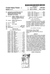
1
Digital Signage Player
Athlon X2 2.8GHz, SSD, POSReady7, HDMIx4
DS-280H Series
User’s Manual
CONTEC CO.,LTD.
Check Your Package
Thank you for purchasing the CONTEC product.
The product consists of the items listed below.
Check, with the following list, that your package is complete. If you discover damaged or missing items,
contact your retailer.
Product Configuration List
DS-280H-DC6413
Name
Pcs.
The main body
1
AC adapter
1
AC cable *1
1
Product guide
1
Warranty Certificate
1
POSReady7 End User License Agreement
1
Setup Manual
1
Serial number label
1
GHOST End User License Agreement
1
Preinstall OS Recovery Procedures
1
Recovery Media
1
*1 Do not use this AC power cable with any devices except for an attached AC adaptor.
Product Configuration Image
* See the Product Configuration List to check if all the components are included for the specified number of units.
DS-280H Series User’s Manual
i
Copyright
Copyright 2012 CONTEC CO., LTD. ALL RIGHTS RESERVED.
No part of this document may be copied or reproduced in any form by any means without prior written
consent of CONTEC CO., LTD.
CONTEC CO., LTD. makes no commitment to update or keep current the information contained in this
document.
The information in this document is subject to change without notice.
All relevant issues have been considered in the preparation of this document. Should you notice an
omission or any questionable item in this document, please feel free to notify CONTEC CO., LTD.
Regardless of the foregoing statement, CONTEC assumes no responsibility for any errors that may
appear in this document or for results obtained by the user as a result of using this product.
Trademarks
Intel, Intel Atom, Intel Core and Celeron are registered trademarks of Intel Corporation. MS, Microsoft
and Windows are trademarks of Microsoft Corporation. Other brand and product names are trademarks
of their respective holder.
ii
DS-280H Series User’s Manual
Table of Contents
Check your package ................................................................................................................................. i
Copyright .................................................................................................................................................ii
Trademarks ..............................................................................................................................................ii
Table of Contents ...................................................................................................................................iii
1.
INTRODUCTION
1
About the Product ................................................................................................................................... 1
Features............................................................................................................................................. 1
Supported OS ................................................................................................................................... 1
Customer Support.................................................................................................................................... 2
Web Site ........................................................................................................................................... 2
Limited One-Year Warranty ................................................................................................................... 2
How to Obtain Service............................................................................................................................ 2
Liability ................................................................................................................................................... 2
Safety Precautions ................................................................................................................................... 3
Safety Information ........................................................................................................................... 3
Caution on the DS-280H Series ...................................................................................................... 3
2.
SYSTEM REFERENCE
5
Specification ............................................................................................................................................ 5
Physical Dimensions ............................................................................................................................... 6
3.
HARDWARE SETUP
7
Before Using the Product for the First Time.......................................................................................... 7
Hardware Setup ....................................................................................................................................... 8
Installation Requirements ................................................................................................................ 8
4.
EACH COMPONENT FUNCTION
9
Component Name.................................................................................................................................... 9
Component Function ............................................................................................................................. 10
DC Power Input Connector: DC-IN .............................................................................................. 10
POWER SW: POWER-SW ........................................................................................................... 10
Display Interface: HDMI ............................................................................................................... 10
USB Ports ....................................................................................................................................... 10
Line in Interface: LINE IN ............................................................................................................ 10
Line out Interface: LINE OUT ...................................................................................................... 10
Giga bit-Ethernet: LAN A – B ...................................................................................................... 11
Serial Port Interface : SERIAL COM1/COM2 ............................................................................. 12
DS-280H Series User’s Manual
iii
5.
BIOS SETUP
13
Introduction............................................................................................................................................13
Starting Setup .................................................................................................................................13
Using Setup.....................................................................................................................................13
Getting Help....................................................................................................................................13
In Case of Problems........................................................................................................................14
A Final Note About Setup..............................................................................................................14
Main .......................................................................................................................................................15
Standard CMOS Features ......................................................................................................................16
Advanced BIOS Features ...............................................................................................................18
Advanced Chipset Features............................................................................................................20
PCIE Configuration ........................................................................................................................21
IGX Configuration.................................................................................................................................22
Integrated Peripherals............................................................................................................................23
Onboard Devices ...................................................................................................................................24
OnChip SATA Device...........................................................................................................................25
OnChip Azalia Device...........................................................................................................................26
USB Device setting ...............................................................................................................................27
Power Management Setup.....................................................................................................................28
PNP/PCI Configurations .......................................................................................................................29
PC Health Status ....................................................................................................................................30
Frequency/Voltage Control ...................................................................................................................31
Defaults Menu........................................................................................................................................32
Supervisor /User Password Setting .......................................................................................................33
Exit Selecting .........................................................................................................................................34
6.
APPENDIX
35
Battery ....................................................................................................................................................35
7.
iv
LIST OF OPTIONS
37
DS-280H Series User’s Manual
1. Introduction
1. Introduction
About the Product
This is STB for signage, working with AMD Athlon™ II 2.8G CPU and ATI Radeon™ E4690 GPU with
enhanced graphics performance helps Full-HD movie to be played smoothly with 4 ports HDMI interface.
SSD can be installed as storage. The body is so compact and supports SATA interface which can
transport data at high speed. It enables you to read high-quality movie, store so big data and transport data
at high bit rate.
DS Series are the products assumed to be used at ordinary environment and market as
"Digital Signage".Operating environment condition, supply period, maintenance period
and other conditions are different from ones of our industrial products (IPC Series,
BOX-PC, PT-Series and others).For details, please consult our retailer.
Features
-
Equipped with four-port HDMI display output (Supported 1080p)
This product has four-port HDMI display output which supports 1080p. It makes it possible to
display on quad monitors.
-
High performance dual core CPU
This product also has AMD Athlon II XLT V66C 2.8GHz (TDP45W). It supports applications which
require high-speed processing.
-
Dual configuration with discrete GPU and GPU which features integrated chipset
This product is equipped with discrete GPU (Radeon E4690) and GPU (Radeon HD3200) which is
integrated with AMD 780E chipset. They support advanced graphics processing
-
Major types of peripherals are supported with rich interfaces
It has a variety of extended interface such as HDMI x4, 1000BASE-T x1, USB2.0 x 4, serial
(RS-232C) x2.
So it can be used for various purposes.
-
Pre-installed Windows Embedded POSReady 7
The OS, Windows Embedded POSReady 7 which is perfect for digital signage use, is pre-installed.
There are many functions on this product. Such as write filters (EWF: Enhanced Write Filter and
FBWF: File-Based Write Filter) and Microsoft Office Viewer that is a file browser for Word, Excel
and PowerPoint.
-
Kinect for Windows Runtime (Pre-installed model)
The installed OS is already equipped with a Runtime module which is required on OS side to trip
Kinect for Windows sensor.You can use this product as an application controller which is equipped
with NUI (Natural User Interface ) that features a control with voice or gestures.
Supported OS
-
Windows Embedded POSReady7
DS-280H Series User’s Manual
1
1. Introduction
Customer Support
CONTEC provides the following support services for you to use CONTEC products more efficiently and
comfortably.
Web Site
Japanese
English
Chinese
http://www.contec.co.jp/
http://www.contec.com/
http://www.contec.com.cn/
Latest product information
CONTEC provides up-to-date information on products.
CONTEC also provides product manuals and various technical documents in the PDF.
Free download
You can download updated driver software and differential files as well as sample programs available in
several languages.
Note! For product information
Contact your retailer if you have any technical question about a CONTEC product or need its price,
delivery time, or estimate information.
Limited One-Year Warranty
CONTEC products are warranted by CONTEC CO., LTD. to be free from defects in material and
workmanship for up to one year from the date of purchase by the original purchaser.
Repair will be free of charge only when this device is returned freight prepaid with a copy of the original
invoice and a Return Merchandise Authorization to the distributor or the CONTEC group office, from
which it was purchased.
This warranty is not applicable for scratches or normal wear, but only for the electronic circuitry and
original products. The warranty is not applicable if the device has been tampered with or damaged
through abuse, mistreatment, neglect, or unreasonable use, or if the original invoice is not included, in
which case repairs will be considered beyond the warranty policy.
How to Obtain Service
For replacement or repair, return the device freight prepaid, with a copy of the original invoice. Please
obtain a Return Merchandise Authorization number (RMA) from the CONTEC group office where you
purchased before returning any product.
* No product will be accepted by CONTEC group without the RMA number.
Liability
The obligation of the warrantor is solely to repair or replace the product. In no event will the warrantor be
liable for any incidental or consequential damages due to such defect or consequences that arise from
inexperienced usage, misuse, or malfunction of this device.
2
DS-280H Series User’s Manual
1. Introduction
Safety Precautions
Understand the following definitions and precautions to use the product safely.
Safety Information
This document provides safety information using the following symbols to prevent accidents resulting in
injury or death and the destruction of equipment and resources. Understand the meanings of these labels
to operate the equipment safely.
DANGER
DANGER indicates an imminently hazardous situation which, if not avoided, will
result in death or serious injury.
WARNING
WARNING indicates a potentially hazardous situation which, if not avoided, could
result in death or serious injury.
CAUTION
CAUTION indicates a potentially hazardous situation which, if not avoided, may
result in minor or moderate injury or in property damage.
Caution on the DS-280H Series
Handling Precautions
DANGER
-
This product supports an attached AC adapter and AC cable only.
-
Always check that the power supply is turned off before connecting or disconnecting power cables
and other cables.
-
Users should not attempt to disassemble or modify this equipment, or to replace components. The
manufacturer may not be able to provide service for equipment that has been modified by the user.
-
This product is not intended for use in aerospace, space, nuclear power, medical equipment, or other
applications that require a very high level of reliability. Do not use the product in such applications.
-
If using this product in applications where safety is critical such as in railways, automotive, or
disaster prevention or security systems, please contact your retailer.
WARNING
-
Do not attempt to replace the battery as inappropriate battery replacement poses a risk of explosion.
-
For battery replacement, contact your retailer as it must be performed as a process of repair.
-
When disposing of a used battery, follow the disposal procedures stipulated under the relevant laws
and/or municipal ordinances.
DS-280H Series User’s Manual
3
1. Introduction
CAUTION
-
-
-
-
-
-
Do not use or store this product in a location exposed to high or low temperature that exceeds range
of specification or that is susceptible to rapid temperature changes.
Example:
- Exposure to direct sun - In the vicinity of a heat source
Do not use this product in extremely humid or dusty locations. It is extremely dangerous to use this
product when it is in concact with water or any other fluid or conductive dust. If this product must be
used in a dusty environment, install it on a dust-proof control panel, for example.
Avoid using or storing this product in locations subject to shock or vibration that exceeds range of
specification.
Do not use this product in the vicinity of devices that generate strong magnetic force or noise. Such
products will cause this product to malfunction.
Do not use or store this product in the presence of chemicals.
To clean this product, wipe it gently with a soft cloth dampened with either water or mild detergent.
Do not use chemicals or a volatile solvent, such as benzene or thinner, to prevent pealing or
discoloration of the paint.
This product’s case may become hot. To avoid being burned, do not touch the case while this product
is in operation or immediately after turning off the power. Avoid installation in a location where
people may come into contact with the case.
CONTEC does not provide any guarantee for the integrity of data on any recording media such as
SSD.
Always remove the power cable from the power outlet before changing hardware configurations such
as the connection of connectors, and/or the setting of jumpers and switches.
To prevent corruption of files, always shutdown the OS before turning off this product.
CONTEC reserves the right to refuse to service a product modified by the user.
In the event of failure or abnormality (unusual smells or excessive heat generation), unplug the power
cord immediately and contact your retailer.
To connect with peripherals, use a grounded, shielded cable.
When transporting this equipment, be careful to protect it against direct vibration and physical shock.
You cannot clear the BIOS settings on CMOS of this product. The product must be repaired if it
becomes unbootable after the change of BIOS settings.
Regarding “VCCI Class A Notice”
The HDMI Cable must be used in the following so that this product may suit the above-mentioned
standard.
HDMI Cable: IPC-HDMI-015 (Options)
Caution on the VCCI Class A
この装置は、クラスA情報技術装置です。この装置を家庭環境で使用すると電波妨害を
引き起こすことがあります。この場合には使用者が適切な対策を講ずるよう要求されるこ
VCCI-A
とがあります。
4
DS-280H Series User’s Manual
2. System Reference
2. System Reference
Specification
Table 2.1. Functional Specification
Model
DS-280H
CPU
AMD Athlon™II 2.8GHz
Chipset
AMD 780E + SB710 Chipset
BIOS
Manufactured by Award
Memory
2GB, DDR2
Integrated:
AMD HD3200 Graphics Core w/ side-port 128MB GDDR3 memory
-DirectXR10 & OpenGL 2.0 capable
-UVD2.0 video & display engines for HD, Blu-ray & 3D
Discrete:
AMD E4690 GPU (320 Cores @ 600MHz; 31W) w/ 512MB GDDR3 memory (128-bit wide)
-DirectXR10.1, Shader 4.1, OpenGL 3.0 capable
-UVD2.0 video & display engines for HD, Blu-ray & 3D
Port 1,2
GPU*1
Port 3,4
Interface
Display
4port (HDMI connector x 1)
Audio
Line-out x 1, 3.5 φ Stereo mini jack
Line-in x 1, 3.5 φ Stereo mini jack
Serial ATA
LAN
USB
1-slot, 2.5inch SATA SSD, 16GB (SLC)
1port (RJ-45 Connector)
Realtek RTL8111C PCI-E Gigabit LAN Controller
4ports (TYPE-A Connector x 4)
USB 2.0-compliant
2port (RJ-50 Connector), RI (Ring Indicator) none
RS-232C
Power Supply
This product supports an attached AC adapter and AC cable ONLY.
(AC adapter specification)
Input voltage
100V-240VAC, 50-60Hz
Input current
2A
Rated output voltage
12VDC
Rated output current
12.5A(Max.)
30,000H (temperature 25 °C FullHD movie playing)
8,700H (temperature 40 °C FullHD movie playing)
Physical dimensions (mm) 250(W) x 210(D) x 35(H) (No protrusions)
Longevity*2
Weight
About 2.1kg
Operating temperature
0 - 40 °C
Storage temperature
-10 - 60 °C
Humidity
10 - 90%RH (No condensation)
Floating dust particles
Not to be excessive
Corrosive gases
None
*1:
Clone display between port 1, 2 (HD3200) and port 3, 4 (E4690) is not available.
*2
This product are designed to use under the good condition.
DS-280H Series User’s Manual
5
2. System Reference
Physical Dimensions
Figure 2.1.
6
Physical Dimensions
DS-280H Series User’s Manual
3. Hardware Setup
3. Hardware Setup
-
Before you start, be sure that the power is turned off.
Before Using the Product for the First Time
Follow the next steps to set up this product:
STEP1
By referring to the information in this chapter, install, connect and set this product.
STEP2
Connect cables.
Connect the cable of necessary external devices, such as keyboard and a display, to this
product using appropriate cables.
STEP3
Turn on the power.
Check if STEP1-2 were correctly done, again.
Check that AC plug is not connected, then insert DC jack of AC adapter into the product.
Insert AC plug into AC inlet. The product will wake up.
If you feel any abnormality after connection, pull out AC plug quickly,
and then check if all installation was correctly done.
*.This product supports an attached AC adapter and AC cable ONLY.
STEP4
Set up BIOS.
By referring to Chapter 5, set up BIOS. This setup requires a keyboard and a display.
* Before using this product, be sure to execute "LOAD SETUP DEFAULTS" to initialize
the BIOS settings to their default values.
(See Chapter 5, "Main Menu.")
CAUTION
Be sure to connect the keyboard and mouse to it before turning the power on for the first time.
DS-280H Series User’s Manual
7
3. Hardware Setup
Hardware Setup
-
Before you start, be sure that the power is turned off.
Installation Requirements
Figure 3.1. Installation Requirements
You can install this product on plastic (LCD monitor), wood, drywall surface over studs, or a solid
concrete or metal plane directly. Ensure the installer uses four M3 length 8mm screws to secure the
system on wall.
Fasteners are not included with the unit, and must be supplied by the installer. The types of fasteners
required are dependent on the type of wall construction.
8
DS-280H Series User’s Manual
4. Each Component Function
4. Each Component Function
Component Name
Figure 4.1. Component Name
Table 4.1. Component Function
Name
DC-IN
Function
This product supports an attached AC adapter and AC cable ONLY.
Check that AC plug is not connected, then insert DC jack of AC
adapter into the product.
Insert AC plug into AC inlet. The product will wake up.
POWER-SW
Power switch
POWER LED
Power ON display LED
ACCESS LED
Disk access display LED
HDMI(E4690/HD3200)
Display(HDMI x4)
USB
USB port connector x2
LINE IN
Line in (3.5φ PHONE JACK)
LINE OUT
Line out (3.5φ PHONE JACK)
LAN
Ethernet 1000BASE-T/100BASE-TX/10BASE-T RJ-45 connector
COM1 / COM2
Serial port RJ-45 connector x2
DS-280H Series User’s Manual
9
4. Each Component Function
Component Function
DC Power Input Connector: DC-IN
This product supports an attached AC adapter and AC cable only.
POWER SW: POWER-SW
POWER SW is provided.
Display Interface: HDMI
This product can be connected with HDMI input external device.
We connect the HDMI input terminal of the video equipment and the external HDMI output terminal of
this unit HDMI cable.You can connect HDMI output terminal of this product and HDMI input terminal of
external video equipment with HDMI cable.
USB Ports
This product is equipped USB 2.0 interface.
Table 4.2. USB Connector
Pin No.
Signal name
1
USB_VCC
2
USB-
3
USB+
4
USB_GND
Line in Interface: LINE IN
A line in connector is provided. You can plug a microphone to this connector for sound input.
Line out Interface: LINE OUT
A line output connector is provided. You can plug a headphone or amplifer-integrated speakers into this
connector.
10
DS-280H Series User’s Manual
4. Each Component Function
Giga bit-Ethernet: LAN A – B
Connector for Giga bit-Ethernet Interface is provided.
Table 4.3. Giga bit-Ethernet Connector
RJ-45
Connector type
Pin No.
Signal name
100BASE-T
1000BASE-T
1
TX+
TRD+(0)
2
TX-
TRD-(0)
3
RX+
TRD+(1)
4
N.C.
TRD+(2)
5
N.C.
TRD-(2)
6
RX-
TRD-(1)
7
N.C.
TRD+(3)
8
N.C.
TRD-(3)
LEDs for display of network statuses:
Right LED: Link LED
Opertion: Green Blinking
Left LED: Operation LED
10M, 100M: Green, 1000M: Orange
DS-280H Series User’s Manual
11
4. Each Component Function
Serial Port Interface : SERIAL COM1/COM2
Connector for Serial Port Interface is provided.
Table 4.4.
Serial Port Interface
Connector type
Pin No.
RJ-45
Signal name
1
RTS
Request to send
2
DTR
Data terminal ready
3
TXD
Transmit data
4
GND
ground
5
DCD
Data carrier detect
6
RXD
Receive data
7
DSR
Data set ready
8
CTS
Clear to send
CAUTION
Do not Insert LAN Cable into Serial Port.
This product may malfunction or cause a failure.
12
DS-280H Series User’s Manual
5. BIOS Setup
5. BIOS Setup
Introduction
This chapter discusses Award’s Setup program built into the product. The Setup program allows users to
modify the basic system configuration.
Starting Setup
The Award BIOS is immediately activated when you first power on the computer.
By pressing <DEL> immediately after switching the system on, or
If the message disappears before you respond and you still wish to enter Setup, restart the system to try
again by turning it OFF then ON. You may also restart by simultaneously pressing <Ctrl>, <Alt>, and
<Delete> keys.
Using Setup
In general, you use the arrow keys to highlight items, press <Enter> to select, use the F5 and F6 keys to
change entries, press <F1> for help and press <Esc> to quit. The following table provides more detail
about how to navigate in the Setup program using the keyboard.
Table 5.1.
Using Setup
Key
Function
Up Arrow
Move to the previous item
Down Arrow
Move to the next item
Left Arrow
Move to the item on the left
Right Arrow
Move to the item on the right
Enter
Move to the item you desired
PgUp
Increase the numeric value or make changes
PgDn
Decrease the numeric value or make changes
F1 key
General help on Setup navigation keys
F5 key
Load previous values from CMOS
F7 key
Load the optimized defaults
F10 key
Save all the CMOS changes and exit
Esc
Main Menu
: Quit without saving changes
Submenus
: Exit Current page to the next higher level menu
Getting Help
Press F1 to pop up a small help window that describes the appropriate keys to use and the possible
selections for the highlighted item. To exit the Help Window press <Enter> key.
DS-280H Series User’s Manual
13
5. BIOS Setup
In Case of Problems
If, after making and saving system changes with Setup, you discover that your computer no longer is able
to boot, we should repair it
The best advice is to only alter settings which you thoroughly understand. To this end, we strongly
recommend that you avoid making any changes to the CPU defaults and the chipset defaults. These
defaults have been carefully chosen by both Insyde and your systems manufacturer to provide the
absolute maximum performance and reliability. Even a seemingly small change to them has the potential
for causing you to be repaired.
A Final Note About Setup
The information in this chapter is subject to change without notice.
14
DS-280H Series User’s Manual
5. BIOS Setup
Main
Once you enter the Award BIOS CMOS Setup Utility, the Main Menu will appear on the screen.
The Main Menu allows you to select from several setup functions and two exit choices. Use the arrow
keys to select among the items and press <Enter> to accept and enter the sub-menu.
Note that a brief description of each highlighted selection appears at the bottom of the screen.
Table 5.2. Main Menu (Display only)
Phoenix – Award WorkstationBIOS CMOS Setup Utility
▶Standard CMOS Features
▶Frequency/Voltage Control
▶Advanced BIOS Features
Load Fail-Safe Defaults
▶Advanced Chipset Features
Load Optimized Defaults
▶Integrated Peripherals
Set Supervisor Password
▶Power Management Setup
Set User Password
▶PnP/PCI Configurations
Save & Exit Setup
▶PC Health Status
Exit Without Saving
Esc : Quit
↑↓←→ : Select Item
F10 : Save & Exit Setup
DS-280H Series User’s Manual
15
5. BIOS Setup
Standard CMOS Features
“Standard CMOS Setup” choice allows you to record some basic hardware configurations in your
computer system and set the system clock and error handling.
If the motherboard is already installed in a working system, you will not need to select this option.
You will need to run the Standard CMOS option, however, if you change your system hardware
configurations, the onboard battery fails, or the configuration stored in the CMOS memory was lost or
damaged.
Table 5.3. Standard CMOS Features
Phoenix – Award WorkstationBIOS CMOS Setup Utility
Standard CMOS Features
▶
▶
▶
▶
▶
▶
Data(mm:dd:yy)
Time(hh:mm:ss)
Fri , Aug 24 2012
00 : 00 : 00
IDE Channel 0 Master
IDE Channel 0 Slave
IDE Channel 2 Master
IDE Channel 2 Slave
IDE Channel 3 Master
IDE Channel 3 Slave
Halt On
[None]
[None]
[None]
[None]
[None]
[None]
[No Errors]
Base Memory
Extended Memory
Total Memory
640K
1833984K
1835008K
Item Help
↑↓←→ : Move Enter : Select +/-/PU/PD : Value F10 : Save ESC : Exit F1:General Help
F5 : Previous Values F6 : Fail-Safe Defaults F7 : Optimized Defaults
Item
Explanation
Date
To set the date, highlight the “Date” field and use the PageUp / PageDown or +/key to set the current time.
The date format is:
Day: Sun to Sat
Month: 1 to 12
Date: 1 to 31
Year: 1999 to 2099
Time
To set the time, highlight the “Time” field and use the <PgUp>/ <PgDn> or +/- key to set the
current time. The time format is:
Hour: 00 to 23
Minute: 00 to 59
Second: 00 to 59
16
DS-280H Series User’s Manual
5. BIOS Setup
The onboard PCI IDE connector provides Primary and Secondary channels for connecting
up to two IDE hard disks or other IDE devices.
Press <Enter> to configure the hard disk. The selections include Auto, Manual, and
None. Select ‘Manual’ to define the drive information manually. You will be asked to
enter the following items.
IDE Channel Master/Slave
CYLS: Number of cylinders
HEAD: Number of read/write heads
PRECOMP: Write precompensation
LANDING ZONE: Landing zone
SECTOR: Number of sectors
This field determines whether or not the system will halt if an error is detected
during power up.
Halt On
No errors:
The system boot will not be halted for any error that may be detected.
All errors:
Whenever the BIOS detect a non-fatal error, the system will stop and you will be
prompted.
All, But Keyboard:
The system boot will not be halted for a keyboard error; it will stop for all other errors.
All, But Diskette:
The system boot will not be halted for a disk error; it will stop for all other errors.
All, But Disk/Key:
The system boot will not be halted for a key- board or disk error; it will stop for all
others.
This field determines whether or not the system will halt if an error is detected
during power up.
No errors:
The system boot will not be halted for any error that may be detected.
All errors:
Whenever the BIOS detect a non-fatal error, the system will stop and you will be
prompted.
Halt On
All, But Keyboard:
The system boot will not be halted for a keyboard error; it will stop for all other errors.
All, But Diskette:
The system boot will not be halted for a disk error; it will stop for all other errors.
All, But Disk/Key:
The system boot will not be halted for a key- board or disk error; it will stop for all
others.
DS-280H Series User’s Manual
17
5. BIOS Setup
Advanced BIOS Features
Table 5.4. Advanced BIOS Features
Phoenix – Award WorkstationBIOS CMOS Setup Utility
Advanced BIOS Features
▶ CPU Feature
▶ Hard Disk Boot Priority
Virus Warning
CPU Internal Cache
External Cache
Quick Power On Self Test
First Boot Device
Second Boot Device
Third Boot Device
Boot Other Device
Boot Up NumLock Status
Gate A20 Option
Typematic Rate Setting
x Typematic Rate (Chars/Sec)
x Typematic Delay (Msec)
Seecurity Option
APIC Mode
MPS Version Control For OS
OS Select For DRAM > 64MB
HDD S.M.A.R.T. Capability
[Press Enter]
[Press Enter]
[Disabled]
[Enabled]
[Enabled]
[Enabled]
[Hard Disk]
[CDROM]
[LS120]
[Enabled]
[On]
[Normal]
[Disabled]
6
250
[Setup]
Enabled
[1.4]
[Non-OS2]
[Disabled]
Item Help
↑↓←→ : Move Enter : Select +/-/PU/PD : Value F10 : Save ESC : Exit F1:General Help
F5 : Previous Values F6 : Fail-Safe Defaults F7 : Optimized Defaults
Item
Explanation
CPU Feature
Press Enter to configure the settings relevant to CPU Feature.
Hard Disk Boot Priority
With the field, there is the option to choose, aside from the hard disks connected,
“Bootable add-in Cards” which refers to other external devices.
Virus Warning
If this option is enabled, an alarm message will be displayed when trying to write on
the boot sector or on the partition table on the disk, which is typical of the virus.
CPU Internal and External
Cache
Cache memory is additional memory that is faster than conventional DRAM
(system memory). CPUs from 486-type on up contain internal cache memory, and
most, but not all, modern PCs have additional (external) cache memory. When the
CPU requests data, the system transfers the requested data from the main DRAM
into cache memory, for even faster access by the CPU. These allow you to enable
(speed up memory access) or disable the cache function.
Quick Power On Self Test
When enabled, this field speeds up the Power On Self Test (POST) after the system
is turned on. If it is set to Enabled, BIOS will skip some items.
First/Second/Third Boot
Device
These fields determine the drive that the system searches first for an operating
system. The options available include Floppy, LS120, Hard Disk, CDROM, ZIP100,
USB-Floppy, USB-ZIP, USB-CDROM, LAN and Disable.
Boot Other Device
These fields allow the system to search for an OS from other devices other than the
ones selected in the First/Second/Third Boot Device.
Boot Up NumLock Status
This allows you to activate the NumLock function after you power up the system.
Gate A20 Option
This field allows you to select how Gate A20 is worked. Gate A20 is a device used
to address memory above 1 MB.
18
DS-280H Series User’s Manual
5. BIOS Setup
Typematic Rate Setting
When disabled, continually holding down a key on your keyboard will generate only
one instance. When enabled, you can set the two typematic controls listed next. By
default, this field is set to Disabled.
Typematic Rate (Chars/Sec)
When the typematic rate is enabled, the system registers repeated keystrokes
speeds. Settings are from 6 to 30 characters per second.
Typematic Delay (Msec)
When the typematic rate is enabled, this item allows you to set the time interval for
displaying the first and second characters. By default, this item is set to 250msec.
Security Option
This field allows you to limit access to the System and Setup. The default value is
Setup. When you select System, the system prompts for the User Password every
time you boot up. When you select Setup, the system always boots up and prompts
for the Supervisor Password only when the Setup utility is called up.
APIC Mode
APIC stands for Advanced Programmable Interrupt Controller. The default setting is
Enabled.
This option is specifies the MPS (Multiprocessor Specification) version for your
operating
MPS Version Control for OS system. MPS version 1.4 added extended configuration tables to improve support for
multiple PCI bus configurations and improve future expandability. The default setting is
1.4.
This option allows the system to access greater than 64MB of DRAM memory when
OS Select for DRAM > 64MB used with OS/2 that depends on certain BIOS calls to access memory. The default
setting is Non-OS/2.
HDD S.M.A.R.T. Capability
By default, this field is disabled.
DS-280H Series User’s Manual
19
5. BIOS Setup
Advanced Chipset Features
This Setup menu controls the configuration of the chipset.
Table 5.5. Advanced Chipset Features
Phoenix – Award WorkstationBIOS CMOS Setup Utility
Advanced Chipset Features
▶ PCIE Configuration
▶ IGX Configuration
Init Display First
NB Power Management
Memory Hole
System BIOS Cacheable
[Press Enter]
[Press Enter]
[IGX]
[Auto]
[Disabled]
[Disabled]
Item Help
↑↓←→ : Move Enter : Select +/-/PU/PD : Value F10 : Save ESC : Exit F1:General Help
F5 : Previous Values F6 : Fail-Safe Defaults F7 : Optimized Defaults
Item
Explanation
Init Display First
The default setting is IGX.
NB Power Management
The default setting is Auto.
Memory Hole At 15M-16M
In order to improve performance, certain space in memory can be reserved for ISA
cards.This memory must be mapped into the memory space below 16 MB. The
choices are Enabled and Disabled.
System BIOS Cacheable
The setting of Enabled allows caching of the system BIOS ROM at F0000h-FFFFFh,
resulting in better system performance.
However, if any program writes to this
memory area, a system error may result.
20
DS-280H Series User’s Manual
5. BIOS Setup
PCIE Configuration
Table 5.6.
▶
▶
▶
▶
▶
▶
▶
▶
▶
PCIE Configuration
Phoenix – Award WorkstationBIOS CMOS Setup Utility
PCIE Configuration
Primary Dual Slot Config
GPP Slots Power Limit , W
GFX Port 1
GFX Port 2
GPP1
GPP2
GPP3
GPP4
GPP5
GPP6
NB-SB Port Features
[Enabled]
[25]
[Press Enter]
[Press Enter]
[Press Enter]
[Press Enter]
[Press Enter]
[Press Enter]
[Press Enter]
[Press Enter]
[Press Enter]
Item Help
↑↓←→ : Move Enter : Select +/-/PU/PD : Value F10 : Save ESC : Exit F1:General Help
F5 : Previous Values F6 : Fail-Safe Defaults F7 : Optimized Defaults
DS-280H Series User’s Manual
21
5. BIOS Setup
IGX Configuration
Table 5.7.
IGX Configuration
Phoenix – Award WorkstationBIOS CMOS Setup Utility
IGX Configuration
Internal Graphics Mode
UMA Frame Buffer Size
IGX Engine Clock Override
x IGX Engine Clock
NB Azalia
[UMA+SidePort]
[Auto]
[Disabled]
500
[Enabled]
Item Help
↑↓←→ : Move Enter : Select +/-/PU/PD : Value F10 : Save ESC : Exit F1:General Help
F5 : Previous Values F6 : Fail-Safe Defaults F7 : Optimized Defaults
Item
Internal Graphics Mode
22
Explanation
The settings for IB828 are Disabled and UMA; while the IB828 has additional settings
of Sideport and UMA+sideport.
DS-280H Series User’s Manual
5. BIOS Setup
Integrated Peripherals
This section sets configurations for your hard disk and other integrated peripherals.
The first screen shows three main items for user to select. Once an item selected, a submenu appears.
Details follow.
Table 5.8.
Integrated Peripherals
Phoenix – Award WorkstationBIOS CMOS Setup Utility
Integrated Peripherals
CIMx-SB700 Revision
▶ Onboard Devices
▶ OnChip SATA Device
▶ OnChip Azalia Device
Onboard Serial Port 1
Onboard Serial Port 2
PWRON After PWR-Fail
▶ USB Device Setting
4.7.0
[Press Enter]
[Press Enter]
[Press Enter]
[3F8/IRQ4]
[2F8/IRQ3]
[On]
[Press Enter]
Item Help
↑↓←→ : Move Enter : Select +/-/PU/PD : Value F10 : Save ESC : Exit F1:General Help
F5 : Previous Values F6 : Fail-Safe Defaults F7 : Optimized Defaults
Item
Explanation
Onboard Serial Port
These fields allow you to select the onboard serial ports and their addresses. The
default values for these ports are:
Serial Port 1: 3F8/IRQ4
Serial Port 2: 2F8/IRQ3
PWRON After PWR-Fail
This field sets the system power status whether on or off when power returns to the
system from a power failure situation.
DS-280H Series User’s Manual
23
5. BIOS Setup
Onboard Devices
Table 5.9. Onboard Devices
Phoenix – Award WorkstationBIOS CMOS Setup Utility
Onboard Devices
Onboard Realtek NIC
Onboard Lan Boot ROM
[Enabled]
[Disabled]
Item Help
↑↓←→ : Move Enter : Select +/-/PU/PD : Value F10 : Save ESC : Exit F1:General Help
F5 : Previous Values F6 : Fail-Safe Defaults F7 : Optimized Defaults
24
DS-280H Series User’s Manual
5. BIOS Setup
OnChip SATA Device
Table 5.10. OnChip SATA Device
Phoenix – Award WorkstationBIOS CMOS Setup Utility
OnChip SATA Device
OnChip SATA Channel
OnChip SATA Type
Combined Mode
[Enabled]
[IDE]
[Disabled]
Item Help
↑↓←→ : Move Enter : Select +/-/PU/PD : Value F10 : Save ESC : Exit F1:General Help
F5 : Previous Values F6 : Fail-Safe Defaults F7 : Optimized Defaults
DS-280H Series User’s Manual
25
5. BIOS Setup
OnChip Azalia Device
Table 5.11. OnChip Azalia Device
Phoenix – Award WorkstationBIOS CMOS Setup Utility
OnChip Azalia Device
HD Audio Azalia
[Enabled]
Item Help
↑↓←→ : Move Enter : Select +/-/PU/PD : Value F10 : Save ESC : Exit F1:General Help
F5 : Previous Values F6 : Fail-Safe Defaults F7 : Optimized Defaults
26
DS-280H Series User’s Manual
5. BIOS Setup
USB Device setting
Table 5.12. USB Device setting
Phoenix – Award WorkstationBIOS CMOS Setup Utility
USB Device Setting
USB 1.0 Controller
USB 2.0 Controller
USB Keyboard Function
USB Mouse Function
USB Storage Function
[Enabled]
[Enabled]
[Enabled]
[Enabled]
[Enabled]
Item Help
*** USB Mass Storage Device Boot Setting ***
↑↓←→ : Move Enter : Select +/-/PU/PD : Value F10 : Save ESC : Exit F1:General Help
F5 : Previous Values F6 : Fail-Safe Defaults F7 : Optimized Defaults
DS-280H Series User’s Manual
27
5. BIOS Setup
Power Management Setup
Table 5.13. Power Management Setup
Phoenix – Award WorkstationBIOS CMOS Setup Utility
Power Management Setup
ACPI function
ACPI Suspend Type
C2 Disable/Enable
Power Management Option
HDD Power Down
Video Off Option
Video Off Method
Soft-Off by PWRBTN
PowerOn by PCIE Card
ACPI XSDT Table
HPET Support
RTC Alarm Resume
x Date (of Month)
x Resume Time (hh:mm:ss)
[Enabled]
[S1(POS)]
[Disabled]
[User Define]
[Disabled]
[Suspend -> Off]
[V/H SYNC+Blank]
[Instant-Off]
[Disabled]
[Enabled]
[Enabled]
[Disabled]
0
0:0:0
Item Help
↑↓←→ : Move Enter : Select +/-/PU/PD : Value F10 : Save ESC : Exit F1:General Help
F5 : Previous Values F6 : Fail-Safe Defaults F7 : Optimized Defaults
Item
Explanation
ACPI Suspend Type
The default setting of the ACPI Suspend mode is S1(POS).
C2 Disable/Enable
The default setting of this field is Disabled.
Power Management Option
This field allows you to select the type of power saving management modes. There are
four selections for Power Management.
Min. Power Saving:
Minimum power management
Max. Power Saving:
Maximum power management.
User Define: Each of the ranges is from 1 min. to 1hr. Except for
HDD Power Down which ranges from 1 min. to 15 min.
HDD Power Down
When enabled, and after the set time of system inactivity, the hard disk drive will be
powered down while all other devices remain active.
Video Off Option
This field sets the video off option. By default, video goes into suspend state and then Off.
Video Off Method
This field defines the Video Off features. There are three options.
V/H SYNC + Blank: Default setting, blank the screen and turn off vertical and horizontal
scanning.
DPMS: Allows BIOS to control the video display.
Blank Screen: Writes blanks to the video buffer.
Soft-Off by PWRBTN
This field defines the power-off mode when using an ATX power supply. The Instant
Off mode allows powering off immediately upon pressing the power button. In the By
Hardware mode, the system powers off when the power button is pressed for more than
four seconds or enters the suspend mode when pressed for less than 4 seconds.
HPET Support
HPET, or High Precision Event Timer (formerly known as Multimedia Timer) is a
hardware timer that is supported under Linux and Windows Vista. It can produce
periodic interrupts at a much higher resolution than the RTC and is often used to
synchronize multimedia streams, providing smooth playback and reducing the need to use
other timestamp calculations such as an x86 CPU’s RDTSC instruction.
28
DS-280H Series User’s Manual
5. BIOS Setup
PNP/PCI Configurations
This option configures the PCI bus system. All PCI bus systems on the system use INT#, thus all installed
PCI cards must be set to this value.
Table 5.14.
PNP/PCI Configurations
Phoenix – Award WorkstationBIOS CMOS Setup Utility
PnP/PCI Configurations
Reset Configuration Data
Resources Controlled By
x IRQ Resources
PCI/VGA Palette Snoop
Assign IRQ For VGA
Assign IRQ For USB
PCI Latency Timer(CLK)
[Disabled]
Item Help
[Auto(ESCD)]
Press Enter
[Disabled]
[Enabled]
[Enabled]
[64]
** PCI Express relative items **
Maximum Payload Size
[4096]
↑↓←→ : Move Enter : Select +/-/PU/PD : Value F10 : Save ESC : Exit F1:General Help
F5 : Previous Values F6 : Fail-Safe Defaults F7 : Optimized Defaults
Item
Explanation
Reset Configuration Data
This field allows you to determine whether to reset the configuration data or not.
The default value is Disabled.
Resources Controlled by
This PnP BIOS can configure all of the boot and compatible devices with the use of
a PnP operating system such as Windows 95.
PCI/VGA Palette Snoop
Some non-standard VGA display cards may not show colors properly. This field
allows you to set whether or not MPEG ISA/VESA VGA cards can work with
PCI/VGA. When this field is enabled, a PCI/VGA can work with an MPEG
ISA/VESA VGA card. When this field is disabled, a PCI/VGA cannot work with an
MPEG ISA/VESA card.
Assign IRQ for VGA/USB
The default value is Enabled
PCI Latency
PCI latency refers to the number of cycles that any device can hold an IRQ before it
is disconnected.
Maximum Payload Size
The default setting of the PCI Express Maximum Payload Size is 4096.
DS-280H Series User’s Manual
29
5. BIOS Setup
PC Health Status
This section shows the parameters in determining the PC Health Status. These parameters include
temperatures, fan speeds and voltages.
Table 5.15. PC Health Status
Phoenix – Award WorkstationBIOS CMOS Setup Utility
PC Health Status
Shutdown Temperature
CPU Warnig Temperature
Current System Temp
Current CPU Temperature
Current GPU Temperature
SYS_Fan Speed
CPU_Fan Speed
Vcore
12V
1.8V
5V
3.3V
VBAT (V)
3VSB (V)
SYS_DC Fan Temperature
SYS_Fan Tolerance Va
CPU_DC Fan Temperature
CPU_Fan Tolerance Va
[Disabled]
[Disabled]
00°C/ 000°F
00°C/ 000°F
00°C/ 000°F
0000 RPM
0000 RPM
00.00V
00.00V
00.00V
00.00V
00.00V
00.00V
00.00V
[70°C/158°F]
[5]
[70°C/158°F]
[5]
Item Help
↑↓←→ : Move Enter : Select +/-/PU/PD : Value F10 : Save ESC : Exit F1:General Help
F5 : Previous Values F6 : Fail-Safe Defaults F7 : Optimized Defaults
Item
Explanation
Shutdown Temperature
This field allows the user to set the temperature by which the system automatically
shuts down once the threshold temperature is reached. This function can
help
prevent damage to the system that is caused by overheating.
CPU Warning Temperature
This field allows the user to set the temperature so that when the temperature is
reached, the system sounds a warning.
This function can help prevent damage to
the system that is caused by overheating.
Temperatures/Voltages
These fields are the parameters of the hardware monitoring function feature of the
board. The values are read-only values as monitored by the system and show the
PC health status.
Smart Fan Temperature
This field enables or disables the smart fan feature. At a certain temperature, the
fan starts turning. Once the temperature drops to a certain level, it’s turn low speed.
30
DS-280H Series User’s Manual
5. BIOS Setup
Frequency/Voltage Control
This section shows the user how to configure the processor frequency.
Table 5.16. Frequency/Voltage Control
Phoenix – Award WorkstationBIOS CMOS Setup Utility
Frequency/Voltage Control
Spread Spectrun
[Disabled]
Item Help
↑↓←→ : Move Enter : Select +/-/PU/PD : Value F10 : Save ESC : Exit F1:General Help
F5 : Previous Values F6 : Fail-Safe Defaults F7 : Optimized Defaults
Item
Spread Spectrum
Explanation
This field sets the value of the spread spectrum. The default setting is Disabled.
This field is for CE testing use only.
DS-280H Series User’s Manual
31
5. BIOS Setup
Defaults Menu
Selecting “Defaults” from the main menu shows you two options which are described below
Load Fail-Safe Defaults
When you press <Enter> on this item you get a confirmation dialog box with a message similar to:
Load Fail-Safe Defaults (Y/N) ? N
Pressing ‘Y’ loads the BIOS default values for the most stable, minimal-performance system operations.
Load Optimized Defaults
When you press <Enter> on this item you get a confirmation dialog box with a message similar to:
Load setup Defaults (Y/N) ? N
Pressing ‘Y’ loads the default values that are factory settings for optimal performance system operations.
32
DS-280H Series User’s Manual
5. BIOS Setup
Supervisor /User Password Setting
You can set either supervisor or user password, or both of then. The differences between are:
SUPERVISOR PASSWORD: can enter and change the options of the setup menus.
USER PASSWORD: just can only enter but do not have the right to change the options of the setup
menus. When you select this unction, the following message will appear at the center of the screen to
assist you in creating a password.
ENTER PASSWORD:
Type the password, up to eight characters in length, and press <Enter>. The password typed now will
clear any previously entered password from CMOS memory. You will be asked to confirm the password.
Type the password again and press <Enter>. You may also press <Esc> to abort the selection and not
enter a password.
To disable a password, just press <Enter> when you are prompted to enter the password. A message will
confirm the password will be disabled. Once the password is disabled, the system will boot and you can
enter Setup freely.
PASSWORD DISABLED:
When a password has been enabled, you will be prompted to enter it every time you try to enter Setup.
This prevents an unauthorized person from changing any part of your system configuration.
Additionally, when a password is enabled, you can also require the BIOS to request a password every
time your system is rebooted. This would prevent unauthorized use of your computer.
You determine when the password is required within the BIOS Features Setup Menu and its Security
option. If the Security option is set to “System”, the password will be required both at boot and at entry to
Setup. If set to “Setup”, prompting only occurs when trying to enter Setup.
DS-280H Series User’s Manual
33
5. BIOS Setup
Exit Selecting
Save & Exit Setup
Pressing <Enter> on this item asks for confirmation :
Save to CMOS and EXIT (Y/N)? Y
Pressing “Y” stores the selections made in the menus in CMOS – a special section of memory that stays
on after you turn your system off. The next time you boot your computer, the BIOS configures your
system according to the Setup selections stored in CMOS. After saving the values the system is restarted
again.
Exit Without Saving
Pressing <Enter> on this item asks for confirmation:
Quit without saving (Y/N)? Y
This allows you to exit Setup without storing in CMOS any change. The previous selections remain in
effect. This exits the Setup utility and restarts your computer.
34
DS-280H Series User’s Manual
6. Appendix
6. Appendix
Battery
Battery Specification
This product uses the following battery.
- Type
: Lithium primary battery
- Model
: BR2032
- Maker
: Panasonic
- Nominal voltage : 3V
- Nominal capacity : 200mAh
- Lithium content
: 1g or less
Removing the battery
Remove the battery according to the following figure.
Figure 6.1. Removing the battery
Disposing the battery
Dispose the removed battery properly as instructed by local government.
DS-280H Series User’s Manual
35
6. Appendix
36
DS-280H Series User’s Manual
7. List of Options
7. List of Options
Display cable only for HDMI input
-
IPC-HDMI-015
HDMI Cable (1.5m)
* Please check our website in order to know the latest information about our options.
DS-280H Series User’s Manual
37
DS-280H Series
User’s Manual
DS-280H-DCxxxx
CONTEC CO.,LTD.
December 2012 Edition
3-9-31, Himesato, Nishiyodogawa-ku, Osaka 555-0025, Japan
Japanese
http://www.contec.co.jp/
English
http://www.contec.com/
Chinese
http://www.contec.com.cn/
No part of this document may be copied or reproduced in any form by any means without prior written
consent of CONTEC CO., LTD.
[12212012]
[12212012]
Management No.
Parts No.
NA02209
LYPQ381