1
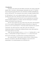
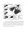
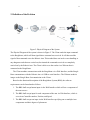
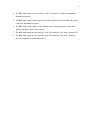
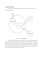
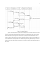
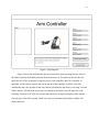
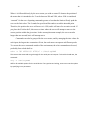
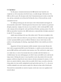
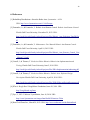
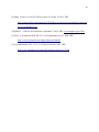
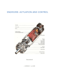
1 BeagleBone Robotic Arm Controller
Dominic Latassa
Thomas Turney
Draft 4
12/1/2014
CEN 4065 Software Architecture & Design
Instructor: Dr. Janusz Zalewski
Software Engineering Program
Florida Gulf Coast University
Ft. Myers, FL 33965
2 1. Introduction
The Robotic Arm, known as the AL5A Robotic Arm features “base rotation, single plane
shoulder, elbow, wrist motion, a functional gripper, and optional wrist rotate.”[1]. There have
been several previous projects done with it, some with control via Windows Embedded [2][3]
and one with Linux[4] [5]. The current project aims to interface it through a Beaglebone board
[6]. The Beaglebone is a low cost development board that is able to boot off of a popular
operating system such as Linux, and features network connectivity and serial interfacing.
It is intended to restore the state of the AL5A Arm to a point where one can control it
remotely through the Beaglebone on an Internet connection. Monitoring the Arm through a
Webcam is also within the scope of the project.
The AL5A Arm is operated via a series of Servo motors. The motors connect through the
SSC-32 Servo controller, featuring MiniSSC-II emulation, which utilizes an Atmega 186
processor [7]. Servos are placed in ports 1-5 on the board, which communicates off of a RS-232
serial interface. The effective Baud rate is either 2400 or 9600, with 115200 for PC
communication. Baud rate is defined as the oscillation of bits per second, which controls how
often electronic pulses are received [8].
Under Linux, the serial inputs are seen as ttyS0 or ttyS1. Searching with dmesg and
using grep can help find the serial input. From there, the minicom utility can be used to
interact with a serial interface, even if this interface is operated on USB protocol [9].
Since control of the SSC-32 chip is based on Atmel, AVR-libc is a library toolset to
interact on a serial interface. This utility allows debugging, as well as systems level
programming in C, the intended language of use for this project [10].
3 Figure 1: Breakdown of Arm Assembly
Lynxmotion, which is the company that created the Arm Controller, supports the baud
rate measurements with RIOS, the default program for configuring the SSC-32 controller [11].
Each component can be configured for position in degrees, as well as maximum grip. The
gravity can also be compensated for, to allow for fine-tuned control when moving to specific
angle degrees. Figure 1 displays an older version of the arm, which allows the rotation of
components with regards to 180 degrees per axis.
4 2. Definition of the Problem
Figure 2: Physical Diagram of the System
The Physical Diagram of the system is shown in Figure 2. The Client sends the input command
to the Beaglebone, which will then signal that a command was received. It will then send the
signal of that command out to the Robotic Arm. This method does not involve error handling or
any dangerous tasks that are carried out, but instead the commands received are completely
carried out by the Robotic Arm. The Client is able to see the results via a Webcam that is
connected to the Beaglebone.
The Client machine communicates with the Beaglebone via a Web Interface, and the Beagle
Bone communicates with the Robotic Arm via USB-to-serial interface. The Webcam sends its
images to the Beagle Bone for transmission to the Client.
Based on the functional description of the Beaglebone System (BBS), the software
requirements can be formulated as follows:
1. The BBS shall accept button input via the Web Interface which will set a component of
the arm to move.
2. The BBS shall accept input for each component of the arm via Web Interface, which is
set as Arm Controller number, Position, and Speed.
3. The BBS shall accept text input via the Web Interface specifying one or multiple Arm
components and their degrees of placement.
5 4. The BBS shall output an error message via the Web Interface if input components are
formatted incorrectly.
5. The BBS shall output a status request via the Web Interface which will show the status of
each Arm component by degrees.
6. The BBS shall output a display of the Robotic Arm's requested position via the Web
Interface through a Web Camera stream.
7. The BBS shall output an error message via the Web Interface if the Arm is powered off.
8. The BBS shall output an error message via the Web Interface if the Arm is unable to
move a component to a proposed position.
6 3. Design Description
From the software requirements, the two interacting pieces of software are the Web
Interface and the BBS.
Figure 3 – Architectural Design
Figure 3 displays the system behavior of the BBS with respect to connected components.
When a command is sent to the BBS from the Web Interface, it is verified and then send to the
Robotic Arm. If executed, the BBS will send a confirmation to the Web Interface. The BBS will
also take the stream of images offered by the webcam for the Client to view. While the BBS only
sends command to the Arm, internally the BBS can monitor the state of the Arm and from there
be able to communicate to the user if the Arm is offline.
7 Figure 4: Sequence Diagram
Figure 4 describes behavior of the system at startup time. The Client connects to the Web
Interface, which begins allowing the BBS to initialize any components that have not yet started.
Before the Client sends a request, they already have an image feed from the Webcam. Once a
request is sent, the BBS will be able to process internally and deliver any errors that might occur,
such as the Robotic Arm being offline. One finished with processing and checking for errors, the
BBS will move the ARM and the Web Interface will be able to send the confirmation message to
the Client.
8 Figure 5: Web Interface
Figure 5 shows the Web Interface the user would face when operating the arm. Each of
the sliders represent individual positions the arm can move in. The status on the left side will
notify the user of any connection or parsing errors of the controller, and if it is currently in
operation. At the bottom, custom code can be put in for the controller to follow. Each line
contains the arm #, the position of the arm, and the speed that the arm moves. Selecting “Execute
Slide Controls” will allow the arm to move according to the sliders, but will ignore the code.
Selecting “Execute Code” will only execute the code that is in input, and ignore slider controls.
First, the user code will be parsed, and if any errors are encountered, the Status window will
display the issue.
9 4. Implementation
Initial implementation of the Robotic Arm involves communication with the standard for
SSC-32 servo controller. The BBS is running Ubuntu 10.10, and the first activity was upgrading
this to the latest version for ARM. The commands to update are as follows:
sudo apt-get install update
sudo apt-get install upgrade
Because of the nature of the lab it is necessary to activate the Ethernet port on the BBS,
which is performed by:
sudo ifconfig eth0 up
sudo reboot
Since the SSC-32 operates with RS 232 communication standards, Ubuntu needs to
recognize the connection interface of USB-to-Serial. The tools for this can be obtained through
apt-get as:
sudo apt-get install stty termios gcc avr-libc
Once these components are installed, active development can begin. Rebooting the
system allows you to dmesg | grep tail to view the recent component connections made.
Stty automatically assigns the USB to serial port as /dev/ttyUSB0. This will be the basis of
the connection.
To open the connection to serial the command will have to be used:
screen /dev/ttyS0 115200
Which will open a blank screen with a single “1”. Any characters entered are a direct feed to the
serial port. To end the session, you type Ctrl-A, Shift-K and say yes to kill the session. Each time
a carriage return is preformed (\r or enter on the keyboard), the SC-332 interprets the command.
Commands can be formatted according to the firmware documentation from lynx motion [12].
An example command is:
#0 P1500 S1000 \r
10 Where # is followed directly by the servo motor you wish to control. P denotes the position of
the motor that it is intended to be. P can be between 500 and 2500, where 1500 is considered
“centered” for the servo. Inputting commands greater or less than the limits will only push the
servo to the limit value. The S stands for speed in milliseconds to reach the intended point.
Therefore, the position the servo will move to is 1500, and it will move for an entire second. If
you place the S before the P, this acts as a timer where the servo will attempt to move to the
correct position within the given time. In the current placement example, the servo can take
longer than one second, but it will attempt not to.
Commands can also be grouped for the servo motor, and by arranging the time values for
each input, the largest time constraint will win, but each motor can operate at different speeds.
To execute the servo commands outside of the environment, the echo command must be used,
preferably from a bash shell as:
echo –e “#1 P2500 #3 P750\r” > /dev/ttyUSB0
This ensures the command can go through for the serial port to interpret. To check the baud rate, the command: Stty –f /dev/ttyUSB0
Will list all available options for the serial device. If any options are lacking, screen can reset the option by specifying it as a parameter. 11 5. Conclusion
For this project, communication between the BBS and the Arm Controller were
completed, as well as connection to the Web Camera, viewable through a Web Interface. The
BBS was able to open a file descriptor to the Serial Communications port in order to control the
Arm, and any commands received from the Web Interface from a Client would carry out the
command to the Arm.
For challenges in this project, the most major is lack of documentation and support for
microcontrollers and the SSC-32 board in particular. Because the Arm Controller was purchased
through a proprietary company, the only sure way to interface with it was through RIOS, which
is the company software designed to work specifically on Windows operating systems. Since the
BBS can only utilize Linux due to the ARM architecture, commands had to be highly customized
for the SSC-32 to accept them.
Another major challenge is the age of the software stack. The most recent update to this
system was in 2005, which was almost 10 years ago. However, within this time span, support for
even the Lynxmotion RIOS system was difficult. Whether it is due to lack of interest of the
product, or the rapid ageing of technology, supporting the Robotic Arm controller proved to be
difficult.
Suggestions for future development would be automatic Arm movement. Because the
Arm is able to respond to the BBS over the Web Interface, it would be trivial to include scripts
onto the BBS itself that could control the Arm in unique ways. This could involve simple waves
at a certain time, or a series of movements that can be extended to the Web Interface as a
clickable button. On a more challenging note, the Web Camera on the BBS can be read from the
image stream. Utilizing this stream, it may be possible to notice the position of the Arm, and a
program could be developed for the Arm to interact with the environment. For instance, if a new
object were placed within the vicinity of the Arm, and the Web Camera were able to detect the
foreign object, the Arm could be manipulated to pick up the object and “toss it” (i.e., the servos
would be prompted in an erratic manner to apply force and power along with a released grip).
This would be recommended as a senior level project, and in some cases even a graduate level
research subject.
12 6. References
[1] RobotShop Distributions. About the Robot Arm. Lynxmotion - AL5A.
URL: http://www.lynxmotion.com/c-124-al5a.aspx
[2] Fernandez, A., & Fernandez, V. Robotic Arm Remote Control. Robotic Arm Remote Control.
Florida Gulf Coast University, November 29, 2013. URL:
http://itech.fgcu.edu/faculty/zalewski/projects/files/Robotic_Arm_Redesign_Final2012.p
df
[3] Fernandez, A., & Fernandez, V. Maintenance User Manual Robotic Arm Remote Control.
Florida Gulf Coast University, April 18, 2013. URL:
http://itech.fgcu.edu/faculty/zalewski/projects/files/Robotic_Arm_Remote_Control_User
_Manual_V4.pdf
[4] Carroll, J., & Thomas, T. Exclusive Online Robotics:Robotic Arm Implementation and
Testing. Florida Gulf Coast University, June 2, 2014. URL:
http://itech.fgcu.edu/faculty/zalewski/projects/files/XRA-ImplementationAndtesting.pdf
[5] Carroll, J., & Thomas, T. Exclusive Online Robotics: Robotic Arm. Software Design
Description Florida Gulf Coast University, April 18, 2014. URL:
http://itech.fgcu.edu/faculty/zalewski/projects/files/XOR-SOftwareDesignDocument.pdf
[6] What is BeagleBone? BeagleBone Foundation, Junes 26, 2014. URL:
http://beagleboard.org/bone
[7] Frye, J., SSC-32 Manual. LynxMotion, June 16, 2010. URL:
http://www.lynxmotion.com/images/html/build136.htm#ssc32feat
[8] Baud TechTerms Inc., March 29, 2013. URL: http://www.techterms.com/definition/baud
13 [9] Matej, Connect to a Serial-USB on Ubuntu 10.10 July 16, 2011. URL:
http://stackoverflow.com/questions/5347962/how-to-connect-to-a-terminal-to-serial-usbdevice-on-ubuntu-10-10
[10] Roth, T., AVR Libc Documentation. September 3, 2012. URL: www.nongnu.org/avr-libc/
[11] Gay, L. Lynxmotion RIOS SSC-32 V1.06 Lynxmotion, July 30, 2009. URL:
http://www.lynxmotion.com/images/data/rios106h.pdf
[12] LynxMotion Inc. SSC-32 Ver 2.0 Firmware Manual. 2005. URL:
http://www.robotshop.com/media/files/pdf/users-guide-ssc-32.pdf