1
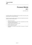
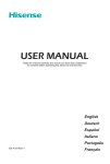
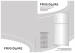
Triguard SC300E
MHB44IND
Pulse Input and Analogue Output
Module
(MHB44IND)
Issue 2 October 2005
INTRODUCTION
PURPOSE
The MHB44IND module (Figure 1-1) supports four pulsed voltage inputs for interfacing with field
detectors, and supplies 0 - 22mA analogue outputs for process control.
The module is a rack mounted, 9U high unit that provides the output control interface between
the SC300E processing environment and the user field environment. It has four current loop
output channels. All field inputs and outputs are galvanically isolated from the SC300E system
but have a common supply connection.
Circuit triplication and voting procedures make the module single-fault tolerant and latent
testing ensures that the failure of a channel will be recogised and reported to the SC300E
system. Front panel indicators show the state of the circuit ‘on-line’ status and the health of
the module. Sockets are provided on the front panel for monitoring the outputs.
The module is compatible with ‘dual slot hot repair’, and can be fitted in any of the ten I/O slots
in the SC300E chassis. ‘Wrong slotting’ is prevented by physical coding. The SC300E system
software identifies the module via a built-in hardware identifier.
Channel outputs leave the module via the DIN 41612 ‘rear plug-up’ system on the chassis
backplane.
This document is intended to provide a general understanding of the MHB44IND sufficient to
enable basic maintenance procedures to be effected in the field.
ASSOCIATED DOCUMENTATION
Reference No
Title
008-5097
Chassis User Manual
008-5201
TPH44AIC 4-Channel Pulse Input and Analogue Output Termination Card
User Manual
008-5108
Triguard SC300E
2
MHB44IND October 2005 – Issue 2
Triguard SC300E MHB44IND Pulse Input and Analogue Output Module
Mechanical coding
block (Upper)
Links JP1 to JP4
Links LK1 to LK3
Connector J1
CommonInterface
(CI) Module
Connector J2
Connector J3
Mechanical coding
block (Lower)
Figure 1-1 General view and front panel detail (safety covers removed)
MHB44IND October 2005 – Issue 2
3
Triguard SC300E
SPECIFICATION
Model
MHB44IND
Channels
4 x pulse inputs
4 x analogue outputs
Architecture
TMR
Indicators
Health, 3 x On Line
Test Point
4 x signal, 1 x common
Output range
0 to 22mA
Maximum resistive field load
400ohm
Resolution
6.25 µA steps
Accuracy @ @ 25°C
+0.2% of full signal range
Maximum input ripple voltage @24V field
supply
12V peak to peak
Maximum input ripple frequency
120Hz
Stability (temperature coefficient)
15ppm/°C
Isolation
1kV to system, commoned supply
Field power supply:
+18Vdc to 30Vdc
Voltage range
Module power consumption
5.5W
Pulse input waveform
Sine/Square/Pulse
Pulse input amplitude
100mV to 132V peak
(NOTE: For sinewave inputs less than 10Hz
amplitude minimum rises linearly to 200mV at
1Hz)
Pulse input duty cycle
10 to 90% up to 3.5kHz
Pulse input width (minimum)
14ms above 3.5kHz
Pulse input impedance
10k ohm
Pulse input frequency resolution
16 bits
Pulse input frequency accuracy
± 0.01% 1Hz to 35kHz
Overall size (mm)
400(9U)H x 397L x 28W
Overall size (inches)
15.75H x 15.63L x 1.1W
Weight
1.7kg
4
MHB44IND October 2005 – Issue 2
Triguard SC300E MHB44IND Pulse Input and Analogue Output Module
ENVIRONMENTAL SPECIFICATIONS
The maximum ambient temperature measured at the hottest point within the Triguard system
shall not be greater than 60 degrees centigrade.
Temperature operating:
+5°C to +60°C
Temperature storage:
-25°C to +70°C
Humidity
5% to 95% non-condensing at ambient <40°C
EMC/RFI Immunity
Tested and certified to IEC 1131-Part 2 1994
Vibration/Shock
Tested and certified to IEC 1131-Part 2 1994
Certification:
General Certification: Ref. SC300E TMR Product Guide (ref 008-5209).
TRANSPORT AND HANDLING
The MHB44IND must be transported and stored in its original packing material, which should
be retained for this purpose.
MHB44IND October 2005 – Issue 2
5
Triguard SC300E
TECHNICAL DESCRIPTION
PHYSICAL
The MHB44IND is a 9U high PCB with integral front panel and rear connectors. A plug-in
daughterboard carries the common interface circuits. Figure 1-1 shows the general layout,
including the location of the connectors, covers and configuration links.
The front panel provides the following: Three ‘On-Line’ indicators A ‘Health’ indicator
An On/Off line request switch
Eight test jacks as monitor points for the pulse input lines
Four received-pulse indicators (one per input pair)
Four test jacks (plus common) for monitoring the output lines.
NOTE
Each monitor point gives 0 to 5.5Vdc negative with respect to common, determining the current
flowing in the corresponding 0 to 22 mA output. Each monitor point has a 10k ohm resistance
in series to prevent malfunction if the monitor point is short circuited - so a high inputresistance meter is required for accurate readings.
MECHANICAL CODING BLOCKS
All Input/Output modules carry two mechanical coding blocks equipped with pins which mate
with holes in corresponding blocks in the chassis and prevent the module being inserted into
the wrong slot. The pins in the module blocks are factory installed in a pattern determined by
the module and corresponding set screws are removed from the chassis coding blocks to
enable fitting. Unused holes are plugged with set screws. The chassis mechanical coding
block configuration for this module is shown in Figure 2-1 .
Figure 2-1 Chassis mechanical coding block configurations
6
MHB44IND October 2005 – Issue 2
Triguard SC300E MHB44IND Pulse Input and Analogue Output Module
MHB44IND October 2005 – Issue 2
7
Triguard SC300E
EXTERNAL CONNECTIONS
All connections to the MHB44IND are made via DIN 41612 connectors.
The upper connector is the system triple I/O bus connector. The middle connector is for the
field inputs and outputs. The lower connector is electrically in parallel with the middle
connector.
System interface
This MHB44IND acts as a slave to the MPP masters, and communication between three
MPPs and the MHB44IND takes place over the triplicated 16 bit parallel I/O - MPP buses that
run along the chassis mounted backplane. The three I/O - MPP buses are connected via the
module’s upper system interface DIN 41612 connector.
Field interface
The MHB44IND input, output and feedback connections are wired via one of the connectors (J2
or J3) to the termination card TPH44AIC.
Pulse inputs
Four isolated voltage inputs of 100mV to 150V peak to peak are provided.
Each pulse input channel has both its lines connected via 100k ohm resistors to the test jacks
and a front panel mounted LED flashes to indicate when pulses are being received.
Current loop outputs
Four 0 to 22mA with common return. The termination card has a precision resistor for each
channel to control the current. This allows two modules to be used for dual-slot hot repair
purposes using the same termination card.
CONFIGURATION LINKS
The module contains a hardware identity circuit that enables system identification of the
module, and seven manual configuration links, JP1 to JP4 and LK1, LK2 and LK3.
Links JP1 to JP4 and LK1 to LK3
Links JP1 to JP4 enable undercurrent and overcurrent monitoring from a special termination
card giving galvanically isolated outputs. Links JP1 to JP4 must beset to the Off position.
Links LK1 to LK3 are described in Section 2.6, Theory of operation.
POWER SUPPLIES
The MHB44IND operates from dual power inputs supplied by the system’s dual redundant
PSUs, that each supply voltages of approximately 5.4Vdc and 12Vdc.
8
MHB44IND October 2005 – Issue 2
Triguard SC300E MHB44IND Pulse Input and Analogue Output Module
THEORY OF OPERATION
The module has four isolated 1Hz to 35kHz pulse-input frequency measuring channels, and
four 0-22mA current output channels using a common 24V supply via termination card
TPH44AIC. The circuits are triplicated except for the final combining of the analogue output
stages into a single voted output.
Common functions
Power supplies and monitoring
The 5V and 12V dual-redundant supplies from the backplane are diode-OR’ed to the three
channels plus an auxiliary section. The analogue output section is isolated by dc/dc converters
providing +5V and ±15V. All the supplies and fuses are monitored by the CI.
An On/Off Line Request switch on the front panel enables a request to be sent to the MPPs
that the module be taken off-line for maintenance purposes or returned on-line.
Mode settings
The module contains a hardware identity circuit that enables system identification of the
module, and seven configuration jumper links (JP1to JP4 and LK1 to LK3). The jumper links
JP1, JP2, JP3 and JP4 must be set to the Off position. The operation of and settings links LK1
to LK3 is described below:
Link 1 allows the module to be set up for 321 or 320 mode operation which sets the threshold
that determines how much of the circuit can be degraded while still preserving overall operation.
320 mode means that the system will continue to function with two out of three serviceable
circuits. If the number falls to one out of three the last read data is maintained. In 321 mode the
system will continue to function with one out of three serviceable circuits. If that fails the last
read data is maintained and the module is taken off-line.
Link 2 (HLV/GTZ) determines whether, in the event of a failure due to 321/320 action, the last
read values are held (HLV) or are set to zero (GTZ).
Link 3 is always set to HW.
Latent fault detection (LFD) on outputs
The voted analogue voltage outputs from each channel are compared in turn with the D-to-A
outputs. The LFD scheme employed is to change each channel’s output in turn by 0.4V for
1ms, first negatively then positively, leaving the other channels unchanged. At each change,
the discrepancy between every channel and the common output is tested by a window
comparator. If a difference is detected on the deviated channel and the other two are 'same'
then no latent fault is detected and the Health LED is illuminated.
MHB44IND October 2005 – Issue 2
9
Triguard SC300E
Voting operates so that the LFD deviations do not appear on the combined output. If a fault
causes health to fail, no further LFD testing is performed.
10
MHB44IND October 2005 – Issue 2
Triguard SC300E MHB44IND Pulse Input and Analogue Output Module
Pulse Inputs
The overall period of one or more cycles of the input is measured. Frequency is calculated by
dividing the number of cycles by the overall period. The pulse input voltage on each
independent path passes via an isolating transformer to an amplifier, which compensates for
the frequency characteristics of the transformer and performs automatic level control to cater for
the wide range of input amplitude (see Figure 2-2). The amplifier output is converted to a pulse
train feeding a 16-bit frequency counter controlled by the Common Interface (CI). Voting
of the frequency data between paths is performed by the RTTS.
The pulse trains from all three independent paths are combined and trigger circuits which
cause the front-panel LEDs to flash. The four red LEDs, corresponding to the pulse-input
channels, flash when pulse trains are being received. Four pairs of sockets are provided for
monitoring the input lines via 100k ohm resistors.
Figure 2-2 Pulse input section - Schematic block diagram
MHB44IND October 2005 – Issue 2
11
Triguard SC300E
Analogue outputs
Five test-sockets are provided for monitoring the output lines: one common terminal via 2.2k
ohm to the +24V field supply, and the other four via 10k ohm to the current-determining
resistors on the termination card. These resistors are 250 ohm, so 20mA of loop-current
corresponds to 5V across them.
The four analogue voltage outputs use 12-bit DACs to produce +0.4V to –6V with respect to
field +24V common, applied across resistors on the termination card. The outputs from the
three channels go through a voting scheme using FETs to select the middle-value output, so
that if one channel fails high or low, one of the other two outputs will be selected (see Figure 23).
The resultant current of 0 to 22mA determined by the voltage and resistor is fed to the field
device, then returns to the supply negative via the termination card.
Figure 2-3 Analogue output section - Schematic block diagram
12
MHB44IND October 2005 – Issue 2
Triguard SC300E MHB44IND Pulse Input and Analogue Output Module
Common interface
The three discrete control circuits in the Common Interface (A, B, and C) are each responsible
for the control of the corresponding one third of the I/O module circuits. Each control circuit
comprises a microcontroller with a dedicated watchdog, data buffers and shared RAM. The
circuit is powered via the module and permits live insertion of replacement modules.
Figure 2-4 Common interface -Block diagram
The microcontroller co-ordinates I/O signal processing, signal path diagnostics, on-line/off-line
status and signal status read/write cycles to and from the MPPs via an I/O communications
bus. All I/O modules have an identification code which is read by the Common Interface and
passed to the MPPs for verification. The on-line/off-line status is determined by the MPPs. If, for
maintenance purposes, the On/Off Line Request switch on the front of the module is
operated, the action is read by all three microcontrollers and the request passed to the MPPs
which may then grant the request. The watchdog extinguishes the Health LED on the I/O
module front panel in the event of a microcontroller failure, LFD action or a voting discrepancy.
MHB44IND October 2005 – Issue 2
13
Triguard SC300E
SUPPLEMENTARY INFORMATION
Connector J1 is the I/O bus.
Field output connectors J2 and J3 are in parallel.
The Channel connections are shown in Table 2-1 and Table 2-2.
Table 2-1. Pulse input connections to Connector J2
Channel
DIN41612 Connector J2
Pulse input
Line A
Pulse input
Line B
1
J2-26a
J2-26c
2
J2-28a
J2-28c
3
J2-30a
J2-30c
4
J2-32a
J2-32c
Table 2-2. Current loop sensing connections to Connector J2
Channel
DIN41612 Connector J2
Current-loop
positive
Current-loop
output
Current-loop
sensing
Current-loop
common
1
J2-10a
J2-10c
J2-18a
J2-18c
2
J2-12a
J2-12c
J2-20a
J2-20c
3
J2-14a
J2-14c
J2-22a
J2-22c
4
J2-16a
J2-16c
J2-24a
J2-24c
J2-1c : Cable screen from earth on chassis backplane
14
MHB44IND October 2005 – Issue 2
Triguard SC300E MHB44IND Pulse Input and Analogue Output Module
The connectors on J2 that are reserved for future use are shown in Table 2-3.
Table 2-3. Connections reserved for future use
Channel
DIN41612 Connector J2
Under-range
logic input
Over-range
logic input
1
J2-2a
J2-2c
2
J2-4a
J2-4c
3
J2-6a
J2-6c
4
J2-8a
J2-8c
J2-1a : System 0V
MHB44IND October 2005 – Issue 2
15
Triguard SC300E
SERVICING
SCOPE
System repair is by module replacement. Faulty modules are not repairable in the field. They
should be replaced by new modules and returned for repair.
CAUTION 1
Before fitting a new module ensure that all the link setting are the same as that on the old
module.
CAUTION 2
The module contains components that may be electrostatically sensitive, it should be
transported and stored in its original packaging material.
DIAGNOSIS
The TriBuild workstation is used for fault diagnosis. In the case of an Input/Output fault, the
Health indicator on the faulty module will be extinguished.
PREPARATION
Use one of the following methods to ascertain whether the chassis I/O slot containing the
faulty module has been allocated a hot repair partner:
•
Check the system drawings
•
Check the chassis wiring configuration
•
Use the I/O Chassis Configuration report on the TriBuild workstation.
Where there is a hot repair partner allocation, use the ‘Dual-slot hot repair’ procedure.
Otherwise use the ‘Single-slot hot repair’ procedure.
CONFIGURATION
Before fitting a new module ensure that all the link setting are the same as that on the old
module.
CAUTION 3
Registers must be initialised to 100 Hex, 256 Decimal.
Ladder logic must be used to prevent a value of less than 256 being written to the outputs or
the module will lose health indication.
16
MHB44IND October 2005 – Issue 2
Triguard SC300E MHB44IND Pulse Input and Analogue Output Module
REMOVAL AND REPLACEMENT
CAUTION 4
Failure to take the faulty module off-line before removing it from the chassis could trigger a fault
alarm.
CAUTION 5
When inserting a module ensure that it is aligned with the markings on the chassis rails, and
that it engages with the top and bottom chassis guides. Improper insertion may cause damage
to the module and/or chassis connectors.
Single-slot hot repair
CAUTION 6
Field loop current will not be supplied during changeover.
1.
Operate the On/Off Line Request switch on the faulty module. The three On Line LEDs
should all go out to indicate that the MPPs have recognised the request and taken the
module off-line. The last-read data input from the module will be maintained until the
new module is on-line.
2.
Slacken the two module securing screws and use the black ejection levers (top and
bottom) to draw the module from its slot.
3.
Insert the new module ensuring that it engages properly in the upper and lower guides
in the chassis, the top and bottom chassis rails carry alignment marks to assist. Pull
out the ejection levers and as the module is pushed back engage the levers on the
chassis rails. The levers should then be used to draw the module into position; some
resistance will be felt as the rear connector pins engage. The module should be fixed
in position with the securing screws.
4.
Operate the On/Off Line Request switch and check that the three On Line indicators
illuminate for one second, extinguish for one second and then illuminate permanently
to indicate that the module has been put on-line. If the indicators do not illuminate
either the first or second time or fail to remain illuminated, then the module must be
considered faulty.
Dual-slot hot repair
1.
Insert the new module into the vacant hot repair slot ensuring that it engages properly
in the top and bottom guides in the chassis, the upper and lower chassis rails carry
alignment marks to assist. Pull out the ejection levers and as the module is pushed
back engage the levers on the chassis rails. The levers should then be used to draw
MHB44IND October 2005 – Issue 2
17
Triguard SC300E
the module into position. Some resistance will be felt as the rear connector pins
engage. The module should be fixed in position with the securing screws.
18
MHB44IND October 2005 – Issue 2
Triguard SC300E MHB44IND Pulse Input and Analogue Output Module
2.
Operate the On/Off Line Request switch on the new module. Ascertain that the three
On Line LEDs on the new module illuminate for one second, extinguish for one second
and then illuminate permanently as the indicators on the old module extinguish. This
sequence indicates that the new module has been put on-line and the old module
taken off-line. If the indicators on the new module do not illuminate either the first or
second time or fail to remain illuminated, the new module must be regarded as faulty.
The old module indicators should remain illuminated indicating that it is still on-line.
3.
If the new module is serviceable, slacken the screws on the old module and use its
ejection levers to remove it from the chassis.
PREVENTIVE MAINTENANCE
No preventive maintenance is necessary.
MHB44IND October 2005 – Issue 2
19
Triguard SC300E
SPARE PARTS
Spare parts and technical advice can be obtained from your local area offices.
20
MHB44IND October 2005 – Issue 2