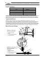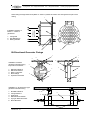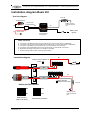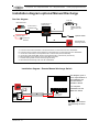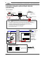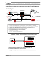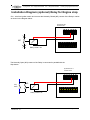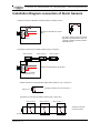
1
Fax: +44(0)1204 373355
E-mail: [email protected]
Control device
Pyrogen Ltd. Tel: +44(0)1204 373300
Active Fire Protection
PyroSense SP-1
Fire Detection & Fire Supression system
Installation & User Manual
PyroSense SP-1
Pyrogen Ltd.
Manual P/N: PYR-DOC-BOAT
Gilnow Mill Business
Centre
Revision No.:
1.0
Spa Road
Bolton U.K.
BL1 4LF
Tele: +44 (0) 1204 373300
Date: 24.02.02
Fax: +44 (0) 1204 373355
e.mail: [email protected]
Page 1 of 48
www.pyrogen.com
Pyrogen Ltd. Tel: +44(0)1204 373300
Fax: +44(0)1204 373355
E-mail: [email protected]
CONTENT
User instructions ................................................................................................................ 4
In the event of a Fire being discovered in the Engine Room ......................................... 4
In the event of an Alarm ................................................................................................. 4
In the event of a Fault .................................................................................................... 4
Alarms ............................................................................................................................ 4
General .............................................................................................................................. 5
PyroSense SP-1............................................................................................................. 5
Fire extinguishing ........................................................................................................... 5
Fault Indications ............................................................................................................. 5
Functional description PyroSense SP-1 ............................................................................ 6
When the system is discharged ..................................................................................... 6
The System Components .................................................................................................. 6
The MAG generator ....................................................................................................... 6
What is Pyrogen? ........................................................................................................... 6
How does Pyrogen work ? ............................................................................................. 7
The SP1 control panel ....................................................................................................... 7
Monitoring....................................................................................................................... 7
Initial start up .................................................................................................................. 7
Service ............................................................................................................................... 8
General........................................................................................................................... 8
Service Life..................................................................................................................... 9
After discharge................................................................................................................... 9
Procedure for replacing the MAG generator .................................................................. 9
Fire extinguishing with Pyrogen and safety ..................................................................... 10
High temperatures........................................................................................................ 10
Hot work ....................................................................................................................... 10
Cleaning after discharge .............................................................................................. 10
Reduced visibility.......................................................................................................... 10
Oxygen level................................................................................................................. 10
Toxicity ......................................................................................................................... 11
Health considerations................................................................................................... 11
Dangerous good declaration ........................................................................................ 11
Installation........................................................................................................................ 11
General......................................................................................................................... 11
Necessary preparations ................................................................................................... 11
Equipment and material ............................................................................................... 11
Tools............................................................................................................................. 12
Order of connection...................................................................................................... 12
Installation of the MAG generator .................................................................................... 13
Minimum clearances .................................................................................................... 13
Limitations .................................................................................................................... 13
Height Limitations......................................................................................................... 14
Typical installations ...................................................................................................... 14
Mono Generator Fixings............................................................................................... 14
Bi-Directional Generator Fixings .................................................................................. 15
TECHNICAL SPECIFICATION PYROGEN..................................................................... 16
Canister Characteristics ............................................................................................... 16
Electrical (Thermal) Characteristics ............................................................................. 16
Aerosol Characteristics (At Maximum Design Concentration) ..................................... 16
Classifications .............................................................................................................. 16
Technical parameters of MAG generators ................................................................... 17
The control panel PyroSense SP-1 ................................................................................. 17
Terminal strip connections ........................................................................................... 18
Conductors and cables ................................................................................................ 18
Optional accessories .................................................................................................... 18
The sensor cable.......................................................................................................... 18
Setting the programming DIP-switch ............................................................................... 19
Manual P/N: PYR-DOC-BOAT
Revision No.: 1.0
Date: 24.02.02
Page 2 of 48
Pyrogen Ltd. Tel: +44(0)1204 373300
Fax: +44(0)1204 373355
E-mail: [email protected]
“Cause effect” matrix .................................................................................................... 19
Programming table Comments ........................................................................................ 20
Software priorities......................................................................................................... 21
Power LED ................................................................................................................... 21
Activated LED............................................................................................................... 21
Test functions ............................................................................................................... 21
Stage 3 – Testing the outputs and remaining inputs.................................................... 21
Trouble shooting .............................................................................................................. 22
General......................................................................................................................... 22
No light in the Power lamp ........................................................................................... 23
Fault LED is lit. ............................................................................................................. 24
Check MAG Generator................................................................................................. 24
The Fault LED is lit ....................................................................................................... 25
Check loop 1 – Sensor cable ....................................................................................... 25
Troubleshooting procedure – sensor cable.................................................................. 25
Fault LED is lit .............................................................................................................. 26
Check loop 2 – Alarm detector(s)................................................................................. 26
Troubleshooting procedure – Loop 2 ........................................................................... 26
Fault LED is lit .............................................................................................................. 27
Check external manual discharge loop........................................................................ 27
Troubleshooting procedure – manual discharge.......................................................... 27
Alarm LED is lit............................................................................................................. 28
Alarm + Activated LED is lit.......................................................................................... 29
List of delivered items ...................................................................................................... 30
Optional equipment.......................................................................................................... 30
Accessories and spare parts........................................................................................ 31
Thermal activation............................................................................................................ 33
Technical data PyroSense SP-1...................................................................................... 34
Installation check list........................................................................................................ 35
Installation LOG ............................................................................................................... 36
Setting of DIP-switch .................................................................................................... 36
SERVICE LOG................................................................................................................. 37
Certificate of conformity ................................................................................................... 38
Installation diagram Basic Kit........................................................................................... 39
Installation diagram optional Manual Discharge.............................................................. 40
Installation diagram optional Spot detector (smoke/heat) ............................................... 41
NOTES............................................................................................................................. 45
Manual P/N: PYR-DOC-BOAT
Revision No.: 1.0
Date: 24.02.02
Page 3 of 48
Pyrogen Ltd. Tel: +44(0)1204 373300
Fax: +44(0)1204 373355
E-mail: [email protected]
User instructions
In the event of a Fire being discovered in the Engine Room
1.
2.
3.
4.
5.
6.
7.
8.
9.
Check that the engine room has been evacuated.
Stop the engine and shut of the fuel supply.
Shut Down Engine room ventilation, if any, close all hatches,
doors or other openings.
Activate the extinguishing system by simultaniously pressing
both push buttons on the control panel.
Disconnect all power sources (elec,gas ect)
Check that all personel are accounted for.
Be prepared for manual intervention by help of portable
extinguisher.
Think safety- lifejackets, survival suits, emergency signals,
alert the coast guard etc.
After 5 minutes check that the fire is extinguished. Only open
doors or hatches slightly and ensure you are protected from
any fire bi-products or gases.
In the event of an Alarm
When an alarm appears on the control panel:
1.
2.
3.
Check if it is Fire or a Fault alarm indication.
If it’s a Fire alarm (i.e. Alarm LED activated) see above In event of a Fire
If it’s a Fault alarm (i.e. Fault LED activated) see below In event of a Fault
In the event of a Fault
When a fault occurs:
1.
2.
3.
Check which lamps are illuminated and deactivate acoustic alarm by
pressing left button “Silence”.
Follow the procedure on page 22.
When the reason for Fault alarm has been detected and the corrective
action has been taken, the control panel can be reset by pressing right button
“Reset”. It is not possible to reset the control panel until the corrective action
has been carried out.
Alarms
Fire alarm
Discharged
Fault
=
=
=
Alarm indicator illuminated and buzzer sounds continuously.
Activated indicator is illuminated and buzzer makes pulsating
sound.
Fault indicator is illuminated and buzzer sounds continiously.
Manual P/N: PYR-DOC-BOAT
Revision No.: 1.0
Date: 24.02.02
Page 4 of 48
Pyrogen Ltd. Tel: +44(0)1204 373300
Fax: +44(0)1204 373355
E-mail: [email protected]
General
PyroSense SP-1
PyroSense SP-1 is a combined alarm, monitoring and discharge panel used for controlling Pyrogen
MAG generators. It can be connected to, & monitor information from, spot detectors, which could be
smoke (optical/ionisation), heat, water or gas as well as a thermal sensing cable.
The control panel can be programmed to operate in either automatic mode, which after receiving a
signal from one of the detectors or sensors indicating the existence of a fire, will fire the MAG units
remotely after a preset delay, or manual mode, allowing for review of the situation before the MAG
units are activated from the panel. See chapter "Applications".
PyroSense SP-1 is programmed at the manufacturing point to just indicate Fire (i.e. Manual Mode),
However the panel can be re-configured to an Automatic setting very easily by altering the DIP
situated on the rear of control panel (Please review the table on page 19).
On the back of the panel there are a number of terminals to allow the user to connect external
sounders, Warning beacons, relay connections for automatic engine shutdown in event of fire as well
as an external manual discharge button should this be required.
In the event of fire the panel will illuminate the Alarm LED and the warning sounders/beacons will
activate, if the panel is set in Manual Mode the Pyrogen MAG generators can only be activated by,
simultaneously, pressing, and holding down both the RED buttons on the front of the panel for 5
seconds, this will activate the Discharge LED and the units will activate. If the panel has been
configured to operate in a fully automatic mode the panel will, once it has received an indication of fire
from the detectors/sensors, automatically activate the Pyrogen MAG generators after a 20 second
warning time.
In order to reset (stop) any activated sounders press the "Silence" button. The Alarm LED will remain
illuminated and can only be reset by pressing the "Reset" button.
In the event that the a fire has been detected by a Thermal Sensing Cable the Fault LED will remain
illuminated until such time as the cable is replaced.
Fire extinguishing
If the MAG unit is discharged, the LED "activated" will be illuminated, the buzzer (and external siren /
alarm if any) will be pulsating.
Sound is reset by pressing the "Silence Button".
If programmed in automatic mode, where the activation is done by signals from detectors, the "Alarm"
LED will be illuminated as well.
If alarm is trigged by the sensor cable, the LED in the control panel will remain illuminated until the
sensor cable is renewed or disconnected. If the sensor cable is disconnected only "Fault" will be
indicated on the control panel. The "Falt" signal will be given until the sensor cable is replaced.
Fault Indications
The Fault LED will illuminate if:
•
•
•
•
•
The cable for the Pyrogen MAG generator goes open
The cable-loop for the external manual discharge button goes open or short circuit
The alarm-loop 1 goes open
The alarm-loop 2 goes open or short circuit
There is a problem with any of the LEDs in the control panel. All LEDs are double and
the spare LED will take over if the main LED is broken.
Fault will be indicated by a continuous tone from the sounder, the "Fault " LED will be illuminated and
alarm loop 1 will give a steady signal for any external siren or alarms that might be connected to the
system.
Manual P/N: PYR-DOC-BOAT
Revision No.: 1.0
Date: 24.02.02
Page 5 of 48
Pyrogen Ltd. Tel: +44(0)1204 373300
Fax: +44(0)1204 373355
E-mail: [email protected]
Functional description PyroSense SP-1
The PyroSense SP-1 has two alarm loops. Alarm loop 1 is the primarily, used to connect the thermal
sensing cable, while alarm loop 2 can be used to connect other spot, smoke (optical/ionisation) or heat
detectors.
At temperatures >180ºC the thermal sensing cable, connected to alarm loop 1, will short circuit and
the panel will activate the alarm. If the control panel is programmed for automatic mode the alarm will
sound for 20 seconds prior to discharge of the Pyrogen MAG generator/s. In this mode output 2 will be
activated simultaneously with the alarm and without any delay. This signal might be used for closing
the ventilation, and stopping the engine. Output 1might be used for any external sirens or alarms. This
output follows the internal buzzer.
The same will happen if alarmsignal is given from detectors connected to loop 2.
As mentioned it is aso possible to use one of the loops to activate automatic discharge of the MAG
unit and use the other loop for activating alarm only (Firealarm). Selection of wich loop to use for the
alternative purposes is done by help of the functional switches at the rear of the control panel. For
extra safety detectors might be connected to both loops, and the control panel programmed to
discharge the MAG generator only if alarmsignal is given from both detectors.
Discharge of MAG generators also can be activated by simultaniously pressing the two pushbuttons,
on the frontside of the control panel, marked "Press" for minimum 5 secconds. A pulsating sound will
confirm that manual discharge signal is activated. After 5 secconds the sound will stop pulsating and a
uniformed sound will be heard. At this moment the MAG generator will be discharged into the
protected enclosure and extinguish the Fire within secconds. Discharge of the MAG unit might also be
activated by external manual push button.
PyroSense SP-1 is prepared for the use of a manual external discharge push button. This input is
also monitored and short circuit or broken loop will give normal fault alarm.
In event of a fire the visual and acoustic alarms will be conscious, and turn to pulsating when the
Pyrogen MAG generator is discharged .
Internal buzzer and output 1 can be reset by pressing the "Silence" button. The alarm signal will be
active until the reset button is pressed. If the detector is still activated the buzzer and the output will
again be activated.
When the system is discharged
In the event that the system is used and the MAG units are discharged, they will need to be replaced
in order to obtain a functional extinguishing system. (See "service" and "after discharge" page 9)
The System Components
The MAG generator
The PyroSense-SP1 control panel is designed to monitor and
discharge the Pyrogen aerosol suppression system. The
suppression system is based on the use of MAG generators
directly activated by an electrical impulse from the control panel.
What is Pyrogen?
Pyrogen is a self-generated Aerosol Fire Extinguishing Agent,
and is one of the most efficient Halon Alternative products
currently available.
As the aerosol produced is self-generated it requires no
pressure cylinders. Pyrogen's method of aerosol generation
provides a sufficient driving force for a rapid discharge and
efficient distribution of the extinguishing agent. No piping is
required.
Manual P/N: PYR-DOC-BOAT
Revision No.: 1.0
Date: 24.02.02
Page 6 of 48
Pyrogen Ltd. Tel: +44(0)1204 373300
Fax: +44(0)1204 373355
E-mail: [email protected]
MAG generators manufactured from marine grade are very compact and they are normally placed
inside the protected enclosure.
The Pyrogen units are called MAG generator (Mass Aerosol Generator).
Operation of the generator is either electrical automatic, electrical manual, thermal automatic or, on
the grenade units, by pin removal.
Pyrogen aerosol is a whitish gas-like medium that is close in density to air. Small particle size ensures
three-dimensional distribution qualities and long suspension times.
Pyrogen aerosol is non-conductive and non-corrosive.
As Pyrogen aerosol stays in suspension for extended periods, it can be removed from the protected
area by any airflow. Any solid fraction of the aerosol that has settled can easily be brushed, blown or
washed away.
How does Pyrogen work ?
The principle of extinguishing action employed by Pyrogen is unique, a special solid chemical, when
electrically or thermally activated, produces combustion products, micron sized dry chemical particles
& gases. Dry chemical particles (mainly potassium carbonates) & a gaseous mixture (mainly carbon
dioxide, nitrogen & water vapour) mix together into a uniform fire-extinguishing aerosol.
Before being released into a protected area the hot aerosol propels itself through a unique solid
chemical coolant, which decomposes absorbing huge amounts of heat, thus ensuring a flameless
discharge and uniform distribution of the cool aerosol within the area.
The high rate of aerosol discharge ensures a tremendous knockdown effect. The micron sized
particles exhibit gas-like three-dimensional qualities that allow the agent to rapidly distribute
throughout the protected area and reach even the most concealed and shielded locations.
Homogenous distribution is achieved in a matter of seconds, while long holding times help to prevent
any re-ignition of the fire.
The SP1 control panel
WARNING! Prior to connecting MAG generators ensure the wires leading to the
generators are not carrying voltage. Connection of MAG generators should always be
the last function in electrical wiring procedure.
The Pyrosense-SP1 is an extremely compact control panel allowing adaptability to most standard
instrument modules (VDO instruments). The panel is both robust and water resistant. All cables,
whether they are for the detectors, power supply or for the MAG generators are connected at the rear
of the panel.
Monitoring
Fire Control
All inputs will be monitored continuously assuming that the
panel remains connected to the power supply. Any short
or open circuit signals will result in a “Fault” alarm.
Power Fault Alarm Activated
PRESS
IN THE EVENT
OF FIRE
Press both buttons for
5 sec.
Manual P/N: PYR-DOC-BOAT
Revision No.: 1.0
PRESS
Initial start up
When electrical source is first connected to panel it will
automatically commence a start up/system test procedure.
This will involve all the LED’s illuminating in sequence and
the internal sounder will give a sequential tone. When this
sequence has finished, the system is operational and
provided no alarm signal from any of the loops, and that
the power source remains healthy, the "Power" lamp will
illuminate.
Date: 24.02.02
Page 7 of 48
Pyrogen Ltd. Tel: +44(0)1204 373300
Fax: +44(0)1204 373355
E-mail: [email protected]
WARNING! Prior to connecting MAG generators ensure the wires leading to the
generators are not carrying voltage. Connection of MAG generators should always be
the last function in electrical wiring procedure.
It is important that prior to the installation of MAG generators the integrity and resistance of the electric
ignition circuit for each MAG generator be checked with the use of a digital multi-meter. The
maximum test current shall not exceed 50 milliamps for a period of 5 minutes. The monitoring current
shall not exceed 5 milliamps.
Resistance of the electric activation circuit shall be within 2.5-4.5 Ohms.
It is also important to check earth fault of every MAG generator. Earth fault resistance must not be less
than 10 mOhm.
Note! In order to save power the “Power” LED does not illuminate until the ignition is switched on.
Should the user wish to run the start up/system test procedure at any time, this can be achieved by
pressing the "Silence" button while electrical power is connected (see page 21). This will ensure all
inputs & outputs are healthy.
Note! Prior to such a test it is important to replace the MAG generator with a test lampe or the
end cap originally supplied.
Service
General
WARNING! Prior to the start of ANY maintenance work, always ensure as the first step,
that wiring to all Pyrogen generator loops have been electrically isolated. Should
thermal automatic operation be used, unscrew the fire conducting cord holders from
all the Pyrogen generators and replace them with the end caps originally supplied.
Failure to do so may result in unwanted spurious discharge.
The PyroSence SP1 does not require any direct maintenance as the panel is self monitoring, however
it is important that a visual inspection of all the elements of the system, including Dectectors, Sensors,
Sounders, Beacons, Remote Manual Release Switches & Pyrogen MAG Generators, is performed on
a monthly basis to ensure that no part of the system has been damaged. Any items found to be
cracked, dented or loose should be recified or replaced.
The visual inspection should consist of:
•
•
•
•
•
Checking that all cabling is securely fastened and that the insulation is not damaged.
Checking that all electrical connections and junction boxes are properly sealed. Moisture
and/or corrosion in connections or junction boxes may, at worst case, discharge the system.
Checking that the MAG unit is not dented or damaged (In the event that a MAG generator has
been damaged or dented it should be disconnected and replaced immediately) and that it has
remained properly secured in its fixings.
Checking the replacement date for the MAG unit.
Ensure that no obstacles have been placed in front of the MAG units discharge nozzle (end
plates) See installation instructions page 11-13.
Manual P/N: PYR-DOC-BOAT
Revision No.: 1.0
Date: 24.02.02
Page 8 of 48
Pyrogen Ltd. Tel: +44(0)1204 373300
Fax: +44(0)1204 373355
E-mail: [email protected]
Service Life
The service life of the Pyrogen MAG unit in total flooding applications under normal conditions is
stated as 10 years from installation, however where the generator is used in local applications or
under conditions of aggressive environment this may be reduced to five years. For further clarification
of the service life please contact your local Pyrogen distributor.
For the disposal of un-discharged generators please contact one of the following:
TECHNOR ASA
Pyrogen (UK)
Dusavikveien 39
P.O.Box 658
4003
STAVANGER
Tel:
+47 51 84 41 00
Fax:
+47 51 84 41 01
E-mail:
[email protected]
Web:
www.technor.no
Gilnow Mill Business Centre
Spa Road, Bolton.
BL1 4LF
UK
Tel:
+44 (0) 1204 373300
Fax:
+44 (0) 1204 373355
E-mail:
[email protected]
Web:
www.pyrogen.co.uk
Distributor:
After discharge
Once a Pyrogen Generator has been activated it is no longer of any use and must be replaced with a
complete unit. If the sensor cable has activated the system then this will need to be replaced also.
Disposal of deactivated Pyrogen generators can be made along with general waste as the remaining
canisters contain on harmful materials. However if the spent canisters are returned to Pyrogen Ltd. or
one of Pyrogens distributors, along with a detailed report on the incident that lead to the activation,
new generators may be purchased at a reduced cost.
Procedure for replacing the MAG generator
Warning: When replacing MAG generators, be aware that immediately after discharge
the canisters outer surface may exceed 200°C. Therefore, protective gloves should be
worn before handling generators until at least 15 minutes after discharge.
•
•
•
•
•
•
•
Disconnect the power supply for the control panel
Disconnect the connector on the spent (discharged) MAG generator
Remove the spent (discharged) MAG generator from the bracket (Please note the warning at
the top of this section)
If the discharge was due to a signal from the Thermal sensing cable install a new cable.
After ensuring that the brackets and fixings are okay fit the new MAG generator.
Ensure that should there be any damage to the connector or flying lead this is replaced.
Reconnect the power supply to the control panel
Switch on the ignition
WARNING! Prior to connecting MAG generators ensure the wires leading to the
generators are not carrying voltage. Connection of MAG generators should always be
the last function in electrical wiring procedure.
Manual P/N: PYR-DOC-BOAT
Revision No.: 1.0
Date: 24.02.02
Page 9 of 48
Pyrogen Ltd. Tel: +44(0)1204 373300
Fax: +44(0)1204 373355
E-mail: [email protected]
It is important that prior to the installation of MAG generators the integrity and resistance of the electric
ignition circuit for each MAG generator be checked with the use of a digital multi-meter. The
maximum test current shall not exceed 50 milliamps for a period of 5 minutes. The monitoring current
shall not exceed 5 milliamps.
Resistance of the electric activation circuit shall be within 2.5-4.5 Ohms.
It is also important to check earth fault of every MAG generator. Earth fault resistance must not be less
than 10 mOhm.
•
•
Reconnect the MAG Generator once the connector has been tested to ensure it is carrying
no voltage (beyond the expected monitoring current)
Ensure that the control panel does not indicate any "Fault".
Fire extinguishing with Pyrogen and safety
One of the main advantages of Pyrogen, compared to conventional chemical extinguishing agents, is
the fact that Pyrogen does not decompose into damaging by-products when in contact with hot
surfaces. This in fact means no secondary damage can be caused after the discharge of the
extinguishing agent.
For safety reasons care should be taken not to expose people to the atmosphere in the enclosure
immediately after discharge of Pyrogen. The enclosure should preferably be ventilated, directly into
the open air. Inhalation of the decomposition products from the fire itself or inhalation of the Pyrogen
aerosol should be avoided. If for any reason it is a necessary to enter the protected area prior to
ventilation having taken place, suitable RPE & other available means of protection should be used.
High temperatures
During discharge the Pyrogen MAG unit can reach temperatures of approximately 250°C at the end
cover (the nozzle) therefore it is important that the minimum safe distances be observed when the
installation of the MAG generators is being considered. Please see the table on pages 13-14.
Temperatures beyond the minimum safe distances will not exceed 75°C
Hot work
As naked flame or prolonged exposure to temperatures above 300°C may cause activation of the
generators, hot work must not be carried out within the vicinity of any generator or thermal sensing
cables. If hot works are absolutely necessary the Pyrogen generators & thermal cables should be
removed to a safe area prior to any work being carried out.
Cleaning after discharge
Following a system discharge the aerosol particles that have settled should be vacuumed, blown,
brushed or, if appropriate, washed away. Protective gloves and goggles should be worn. A respirator
or mask should be worn. Large amounts of residue that are allowed to absorb moisture may become
electrically conductive over a period of time.
Reduced visibility
Pyrogen is intended for use in normally unoccupied areas principally due to the high obscuration
caused by the aerosol during and after discharge.
Oxygen level
Pyrogen chemically attacks the fire, breaking the flame chain reaction. It does not extinguish fires by
oxygen depletion. After discharge, oxygen levels will remain at or about normal.
Manual P/N: PYR-DOC-BOAT
Revision No.: 1.0
Date: 24.02.02
Page 10 of 48
Pyrogen Ltd. Tel: +44(0)1204 373300
Fax: +44(0)1204 373355
E-mail: [email protected]
Toxicity
Inadvertent exposure to Pyrogen aerosol should always be avoided. Toxicological information refers to
an inadvertent exposure to the aerosol in the event of accidental discharge in a non-fire situation.
The main ingredients of the Pyrogen aerosol are solid potassium carbonates, nitrogen gas, carbon
dioxide gas and water vapour. At normal extinguishing concentrations these products present little
health hazard to personnel. However, small amounts of potentially hazardous by-products of the
aerosol-generating combustion reaction, such as carbon monoxide and nitrogen oxides will be
produced. Their actual concentrations depend on Pyrogen design factor used and type of enclosure
under protection. Their toxicological characteristics depend upon the actual concentrations achieved
and duration of exposure.
3
Exposure to a Pyrogen design factor of 100 g/m , which is typical for class B fires in total flooding
applications, for up to 5 minutes, is normally considered to represent a minor risk to personnel and
may cause only moderate local irritation of the upper respiratory tract and to the eyes.
Health considerations
A by-product of Pyrogen aerosol-generating combustion reaction is fine potassium carbonate particles,
small enough to be inhaled by persons not wearing RPE. There are no known toxicological long-term
effects of these soluble micron sized particles, and physiological effects of deep lung penetration are
usually a concern for insoluble sub-micron particles as they can interfere with pulmonary functions.
However, there are clear European guidelines controlling the exposure of persons to fine particles,
irrespective of their nature. Further information is available in BS EN 481:1993 & BS EN 451:1993,
and in CoSHH supportive documents EH40/98 & EH44 and MDHS 14/2.
Noise. The sound output & frequency at the time of activation and during discharge is similar to that
produced by other extinguishing agents. Consequently, no specific precautions need to be taken.
Dangerous good declaration
Pyrogen is a Class 4.1 article in accordance with the United Nations Dangerous Goods Classification
Code.
Installation
General
Prior to installation of the any Pyrogen system the engine must be shut down and the + ve terminal of
the battery disconnected. The battery shall not be reconnected until the installation is finalised. Please
ensure that you have read the installation manual carefully, planned and prepared the installation in
detail, and have ensured that you have all equipment and tools required available prior to start up of
the installation.
Necessary preparations
The following equipment / materials should be prepared prior to installation:
Equipment and material
1.
2.
3.
4.
5.
6.
7.
Fireproof screened cable type Radox FR 125 2x 0.75 (15m)
Available outlet on the fuse box (min. 2A)
Junction box (ELE 1242802)
Fastening equipment (cable clips, screws, Schotts tape, cable strips etc.)
Sensor cable for heat detection (if to be used)
Adhesive sign "Warning" (SPE-PYR-1)
Adhesive sign "Service" (SPE-PYR-2)
Manual P/N: PYR-DOC-BOAT
Revision No.: 1.0
Date: 24.02.02
Page 11 of 48
Pyrogen Ltd. Tel: +44(0)1204 373300
Fax: +44(0)1204 373355
E-mail: [email protected]
Tools
1.
2.
3.
Hand tools screwdriver and pincers
Drill with 3.0 & 10mm drill bit
Hole cutter for making circular hole with 60mm Ø (if SP-1 is to be flush mounted)
Order of connection
1.
2.
3.
4.
5.
6.
7.
8.
9.
10.
11.
12.
13.
14.
15.
16.
17.
18.
19.
20.
21.
22.
23.
Turn off the engine and disconnect the batteries +ve pole.
Make a 60mm hole for the control panel. Alternatively the control panel may be installed in
a spare instrument module, or separate box. It is important that the control panel (SP-1) is
installed in an easily accessible space, in the event of a fire and in such a way that a fire
in the engine room would not block the access to the control panel.
Fix the MAG unit/s, detectors (if any), remote manual discharge switch and the thermal
sensing cable, should these be required.
Install the junction box in the vicinity of the engine room or in the engine room itself.
Install cable from the control panel (SP-1) and the junction box (for connection of MAG
generator/s)
Install the cable from the control panel SP-1 to the junction box for the sensor cable (If
required)
Install cable from the control panel SP-1 to the junction box for spot detectors (If required)
Install cable from the control panel SP-1 to the remote manual discharge switch (If
2
required) (Radox 125 FR 2 x 0.75mm )
2
Install the wire from SP-1 to the ignition switch (Red 1 x 0.75mm )
2
Install the wires from the fuse box to the control panel SP-1 (2 x1.5 mm )
Install the cables for auxiliary equipment such as sounders, beacons, ventilation and /or
automatic engine stop etc.
If used connect the thermal sensing cable to the junction box.
If used connect any extra sounders or beacons.
Connect any other auxiliary equipment (ventilation, automatic engine stop etc.)
If required connect the remote manual discharge switch.
Connect wire from main ignition switch to Pyrosense SP-1 control panel.
Connect wires for power in the fuse box and Pyrosense SP-1 control panel.
Configure the DIP-switches for the installation (rear of panel)
Confirm & verify all the connections.
Reconnect the battery.
Switch on the ignition & check that the "Power" LED on the control panel is illuminated.
Check to ensure that neither the “Alarm” nor "Activated" LED’s are activated on the
SP-1control panel. The "Fault" LED will be illuminated as the Pyrogen MAG generators
have not yet been connected. However before proceeding further with the installation
procedure, check to ensure that at this stage that the cables leading to and intended for
the MAG generators are carrying no voltage (beyond the expected monitoring current).
If OK switch the ignition off and disconnect the batteries +ve terminal.
Note: It is important that prior to the installation of MAG generators the integrity and
resistance of the electric ignition circuit for each MAG generator be checked with the use
of a digital multi-meter. The maximum test current shall not exceed 50 milliamps for a
period of 5 minutes. The monitoring current shall not exceed 5 milliamps.
Resistance of the electric activation circuit shall be within 2.5-4.5 Ohms.
It is also important to check earth fault of every MAG generator. Earth fault resistance
must not be less than 10 mOhm.
WARNING! Prior to connecting MAG generators ensure the wires leading to the
generators are not carrying voltage. Connection of MAG generators should always
be the last function in electrical wiring procedure.
Manual P/N: PYR-DOC-BOAT
Revision No.: 1.0
Date: 24.02.02
Page 12 of 48
Pyrogen Ltd. Tel: +44(0)1204 373300
24.
25.
26.
27.
28.
29.
30.
Fax: +44(0)1204 373355
E-mail: [email protected]
Connect the MAG generator/s
Re-connect the batteries +ve terminal
Switch on the ignition
After the control panel has run through the initially start-up sequence the "Power" LED
should be the only LED illuminated.
Fix “Warning” signs & operating instructions as well as any location specific Fire
procedure instructions at the control panel and any remote activation points.
Affix Installation date, future service date & maintenance or replacement date information
on the MAG generator.
Finally ensure that the Installation details, maintenance protocol and checklist on pages
35-36 have been completed
If at this point, or indeed at any point during the installation, there are any problems with the system,
please refer to the chapter on “Trouble Shooting.
Installation of the MAG generator
The Pyrogen MAG generator/s should be installed in the best possible position to ensure that the
aerosol will have chance to mix evenly within the, to be, protected area. Areas where the MAG
generator will be exposed to high temperatures (+50ºC) or high humidity should be avoided. Also due
to the high temperature of the aerosol on discharge it is advised to ensure that they are not directed
towards sensitive or delicate instrumentation.
Care should be taken to ensure that the positioning of the MAG generators is beyond the specified
safe distances, as shown in the table below, and the required safe distance for the MAG type is
observed.
Minimum clearances
MAG-02
MAG-1
MAG-2
MAG-3
MAG-4
(From each end nozzle)
MAG-5
MAG 5/2 (From each end nozzle)
MAG-11...MAG-17
150 mm
300 mm
400 mm
700 mm
1000 mm
700 mm
1500...2000 mm
Also it is important to try to, unless absolutely unavoidable, avoid positioning the generators at head
height or in close proximity to egress doors nor emergency exits or areas that could lead to a
dangerous situation should an unintended discharge occur.
The Pyrogen MAG generators come in two distinct types, “Mono” versions with one end plate nozzle
i.e. activating from one end (these include the MAG 1, 2, 3, 5, and larger MAG 11, 12, 13, 14, 15, 16 &
17) and the “Bi-directional versions” with two end plate nozzles i.e. activating half their capability from
each end (these include the MAG 4 & 5/2). If a “Mono” type MAG is to be installed, it can be fitted in
such a way to direct the aerosol towards the area of considered risk. If the “Bi-directional” MAG is to
be fitted, this should be fitted in the centre of the area to be protected to allow the low of aerosol over
both side of the area of considered risk.
When more than one MAG generator is to be connected to the PyroSense SP-1 control Panel they
should be connected in series to ensure that the control panel will monitor all generators.
See page 10-13 & 14-15 for limitations & safety instructions prior to any installation of MAG
generators.
Limitations
The Pyrogen extinguishant, being a hot aerosol, has a tendency to rise upward on its release due to
buoyancy forces (low specific weight compared to air). As such, the aspect of spatial distribution
needs to be addressed. Therefore in order to ensure an even distribution it requires that a height
limitation for the protected enclosure be set for each individual Pyrogen generators:
Manual P/N: PYR-DOC-BOAT
Revision No.: 1.0
Date: 24.02.02
Page 13 of 48
Pyrogen Ltd. Tel: +44(0)1204 373300
Fax: +44(0)1204 373355
E-mail: [email protected]
Height Limitations
MAG-1
MAG-2
AG-3
MAG-4 - MAG-5
MAG-11 – MAG 12
MAG 13 – MAG 14
MAG 15 – MAG 16m
MAG-17
1,000 mm
1,250 mm
2,500 mm
3,000 mm
3,500 mm
4,000 mm
4,500 mm
5,000 mm
It is important to be aware off the fact that Pyrogen requires a sealed, or as sealed as is suitable, area
& that big openings in the engine room compartment will cause leakage of Pyrogen aerosol. This
could, in a worst-case scenario, lead to fire not being extinguished. Therefore it is of vital importance
that all hatches & ventilation fans or ducts be closed and the engine/s are stopped prior to discharge.
Typical installations
MAGS 02 - MAG 5 are attached by using the supplied bands or brackets. For “mono” type
extinguishers (MAG 1, MAG 2, MAG 3 & MAG 5/1) arrange the band around the centre of the casing.
For “bi” type extinguishers (MAG 4 & MAG 5/2), two bands should be used, these should be at a
suitable distance from either end to allow good support and fixing. The MAG 4 has a special bracket
arrangement that requires the bands to be fitted at each end of the generator. Ensure that the bands &
brackets are tightened sufficiently using suitable spanners, and make sure that the unit is well held.
Mono Generator Fixings
2
3
1
4
Installation of “mono” type
generator with band fixing
1.
2.
3.
4.
4
Bolt M6 & washer
Band
Pyrogen MAG Generator
Nut M6 & washer
4
2
1
1&4
3
4
1
Installation of “mono” type
generator with band fixing using
an alternative bracket
arrangement
1. Bolt M6 & washer
2. Band
3. Pyrogen MAG Generator
4. Nut M6 & washer 4
Manual P/N: PYR-DOC-BOAT
Revision No.: 1.0
1
1
4
Date: 24.02.02
Page 14 of 48
Pyrogen Ltd. Tel: +44(0)1204 373300
Fax: +44(0)1204 373355
E-mail: [email protected]
When fitting the larger MAG units (MAG 11- MAG 17) these have their own arrangement as part of the
casing
1
1
2
3
Direction of
Aerosol Efflux
Installation drawing of
MAG 11 – MAG 17
generators
Fixing Bolt
Exit Diaphragm
MAG generator
3
1
2
1
Bi-Directional Generator Fixings
1
1
2
5
1
5
Installation of MAG 4
generator with band fixing
& special end brackets
2
4
3
4
1.
2.
3.
4.
5.
M6 Bolt & Washer
M6 Nut & Washer
MAG 4 generator
Band fixings
Special end bracket
3
2
Installation of “bi-directional” type
generator with band fixing
1.
2.
3.
4.
5.
6.
Bolt M6 & Washer
Fixing Bracket 1
Wall Plugs
M6 Bolt Nut & Washer
Pyrogen MAG Generator
Band Brackets
Manual P/N: PYR-DOC-BOAT
Revision No.: 1.0
1
1
Wood or Concrete Ceiling
3
1
5
2
4
Date: 24.02.02
6
Page 15 of 48
Pyrogen Ltd. Tel: +44(0)1204 373300
Fax: +44(0)1204 373355
E-mail: [email protected]
TECHNICAL SPECIFICATION PYROGEN
Pyrogen Generator
Canister Characteristics
Material
Max/Min Ambient
Shock
Vibration
Corrosion Resistance
Impact Resistance
Humidty
Marine Grade Aluminium
- 50°C ~ + 60°C
Tested to 10g for > 13,000 Impacts
5g @ 50 ~ 250Hz
Greater than UL 1058
IP558
=96%
Electrical (Thermal) Characteristics
Supervision/Monitoring Circuit
Activation
Connector
Aerosol Characteristics
Potassium Carbonates, solid
Nitrogen Gas
Carbon Dioxide Gas
Carbon Monoxide Gas
Nitrogen Oxide Gas
Ammonia Gas
Temp at Nozzle + 500 mm
Oxygen (level)
Holding Time
=1mA
=400mA @ 6/12/24V for 10mS
4 pin Military Type 2 PMDT Analog MIL-C-5015
(At Maximum Design Concentration)
~ 7g/M3
~ 70% by vol.
~ 1.2% by vol.
~ 0.4% by vol.
40 – 100 ppm.
~ 0.075% by vol.
= 75°C
17% to 29% (typical)
= 60 mins
Classifications
Suitable for fires
Handling & Transport
Packaging Group
Manual P/N: PYR-DOC-BOAT
Revision No.: 1.0
Class A – Combustible Solids
Class B – Flammable Liquids
Class C – Flammable Gases
Class E – Electrically Energised Fires
Class F – Fats & Cooking Oils
Accordance with UN 1325 & Dangerous Goods Code 4.1
Haz. Chem. Code 2[Y] E
III
Date: 24.02.02
Page 16 of 48
Pyrogen Ltd. Tel: +44(0)1204 373300
Fax: +44(0)1204 373355
E-mail: [email protected]
Technical parameters of MAG generators
Technical parameters of the current range of MAG generators are as follows:
Parameter
MAG
02
Total Mass Of Generator (g)
3
3
Protected Volume (m @ 100g per m )
Generator Type (Mono or Bi-Directional)
Length of Generator (mm)
Diameter of Generator (mm)
Discharge Time (s)
MAG
1
MAG
2
MAG
3
MAG
4
MAG
5
MAG
5/2
125
650
750
1,000
4,000
2,000
2,000
0.20
0.60
1.0
2.0
10.0
5.0
5.0
Bi
Mono
Mono
Mono
Bi
Mono
Bi
120
75
90
135
375
200
300
40
75
75
75
95
95
75
<3.5
<3.5
<6.0
<7.5
<10.0
<7.5
<7.5
Parameter
MAG
11
MAG
12
MAG
13
MAG
14
MAG
15
MAG
16
MAG
17
Total Mass Of Generator (g)
3
3
Protected Volume (m @ 100g per m )
Generator Type (Mono or Bi-Directional)
Length of Generator (mm)
Diameter of Generator (mm)
Discharge Time (s)
11,000
13,500
19,000
37,000
40,000
50,000
58,000
12
17
27
46
50
65
85
Mono
Mono
Mono
Mono
Mono
Mono
Mono
180
245
245
260
175
225
285
245
245
305
400
490
490
490
<10.0
<10.0
<10.0
<10.0
<10.0
<10.0
<10.0
The control panel PyroSense SP-1
The terminals on the SP-1 are of screw/clamp type. Make sure that a suitable amount of the insulation
on the cables/wires is removed and tighten down the terminal screw until the wire is securely held. It is
only recommended that one conductor be placed in each terminal & that the maximum conductor size
2
be 1.5mm
Fire Control
DIP-switch
14
13
12
11
10
9
Power Fault Alarm Activated
10
8
PRESS
IN THE EVENT
OF FIRE
7
6
5
4
3
2
1
PRESS
Press both buttons for
5 sec .
It is suggested that all out cable sheaths are removed at approximately 300mm from the ends of the
cables, and only internal cores be brought to the SP-1 control panel for fixing at the terminals. All
cables should be anchored via cable clips or cable tied to other cable bundles.
Manual P/N: PYR-DOC-BOAT
Revision No.: 1.0
Date: 24.02.02
Page 17 of 48
Pyrogen Ltd. Tel: +44(0)1204 373300
Fax: +44(0)1204 373355
E-mail: [email protected]
Terminal strip connections
1
Battery (+ ) 12 or 24 V (Through a 3A fuse)
2
Battery (–) GND .
3
Pyrogen MAG generator (+)
4
Pyrogen MAG generator (-)
5
Loop 2 (+)
6
Loop 2 (GND).
7
Remote Manual Discharge Switch (+).
8
Remote Manual Discharge Switch (GND).
9
Out 1 (+)
10
Out 1 & 2 (GND)
11
Out 2 (+)
12
Loop 1 (+)
13
Loop 1 (GND).
14
Ignition +
Conductors and cables
The conductors from the control panel to the sensor cable and to the MAG unit must be as short as
2
possible. The conductors shall have a minimum size of 0.75mm , and the maximum length is 20
metres.
Optional accessories
Sounders and beacons should be situated in such a way that they can be easily heard, and seen, from
the pilot/drivers/operators position. If required extra sounders and beacons may be added in so that it
is possible to hear and see them from all locations. It is also possible to connect existing sounders
and/or beacons to the control panel to (see diagram on page 42).
NOTE! Ensure that all Beacons and Sounders are visible & audible from all areas.
The sensor cable
The Thermal Sensing cable is supplied complete with the End Of Line (EOL) resistor required, and
only needs to be connected at one end.
When installing the cable in the area to be protected it is important to install the cable at a point were
possible fire risks may occur, and that any heat produced in the event of a fire can reach the as
greater amount of the circumference of the cable as is possible. When installing, & while considering
the best routing of the cable, be careful to ensure that it is not to close to high running temperature
items like exhaust manifolds etc. as this cable will activate at temperatures above 180°C.
The Thermal Sensing cable can be secured with the cable ties provided, however caution should be
taken to ensure that these are not over tightened as this may cause the cable to short and give
spurious indications.
Caution! Ensure that, while the Thermal Sensing cable is securely fixed it is not over
tightened.
Manual P/N: PYR-DOC-BOAT
Revision No.: 1.0
Date: 24.02.02
Page 18 of 48
Pyrogen Ltd. Tel: +44(0)1204 373300
Fax: +44(0)1204 373355
E-mail: [email protected]
Setting the programming DIP-switch
“Cause effect” matrix
Loop 1 = ALARM
X X 1 0
Loop 2 = ALARM
1 0 X X
Loop 1 & 2 = ALARM
1 1 1 1
Loop 1 = ALARM
X X 0 0
Loop 2 = ALARM
0 0 X X
Loop 1 = ALARM
X X 0 1
Loop 2 = ALARM
0 1 X X
Manual discharge by front
buttons
Remote Manual
Discharge=ALARM
Loop 1 = FAULT
(Break in the cable loop)
Loop 2 = FAULT
(Break or shorted loop)
Remote Manual
Discharge = FAULT
(Break or shorted loop)
MAG loop = FAULT
(Break in the cable loop)
O
O
O
O
O
O
O
O
O
X X X X
O
O
O
O
O O
O O
O
O
O O
O
O
O O
O O
O
O
O
O
NOTE
Fault LED
Alarm LED
Mom. Discharge
Delayed Discharge
O O O
O O O
O O O
O
O
O
O
X X X X
Out. 2
DIP SW.
4 3 2 1
Out. 1 Intermittent
Factory default = all switches off
Out. 1 Continuous
4 3 2 1
Buzzer Intermittent
ON
Buzzer Continuous
OFF
Activation Confirmed LED
1 =ON, 0 = OFF, X = No Effect
1
2
3
4
5
6
7
8
9
X X X X
O
O
O
10
X X X X
O
O
O
11
X X X X
O
O
O
12
X X X X
O
O
O
13
Indicating an alarm situation
Indicating activating of the MAG generator (discharge)
Indicating confirmed activating of the MAG genrator
Indicating a fault situation
The DIP switches can be changed and set by using a pen or something of similar size. Once the DIP
switches are set, they can be sealed using the enclosed sealant.
Manual P/N: PYR-DOC-BOAT
Revision No.: 1.0
Date: 24.02.02
Page 19 of 48
Pyrogen Ltd. Tel: +44(0)1204 373300
Fax: +44(0)1204 373355
E-mail: [email protected]
Programming table Comments
1.
2.
3.
4.
5.
6.
7.
The Alarm loop 1 can be used to initiate a delayed (20 sc.) activation of the Pyrogen MAG
generator. Sensors can either be of linear heat line detector or a spot detector (heat, UV/IR or
smoke types) types. The EOL resistor required is 47kO. The alarm condition is a shorted loop. If
the loop is broken a “Fault” will be indicated. The alarm contacts must be set in a normally open
(NO) position.
The Alarm loop 2 can be used to initiate a delayed (20 sc.) activation of the Pyrogen MAG
generator. Sensors can either be of linear heat line detector or a spot detector (heat, UV/IR or
smoke types) types of voltages free contact type (NC). The EOL resistor required is 47kO in
series and a 47kO in parallel to the NC contact of detector and the other resistor. Alarm condition
is a 47kO input (open contact of sensor).
If the loop is broken or short circuit “Fault” will be indicated. The normal situation is a loop
resistance of 23,5kO.
A combination of Alarm loop 1 and Alarm loop 2 can be used to initiate a delayed (20 sc.)
activation of the Pyrogen MAG generator.
The Alarm loop 1 can be used to initiate an Alarm situation (fire alarm, pressure switch monitoring
etc.).
The sensors might be one or more spot detectors, CO or propane detectors, water leakage
detector etc. The loop must be terminated with an EOL resistor of 47kO. Alarm condition is a
shorted loop. If the loop is broken “Fault” will be indicated. The alarm contacts must be set in a
normally open (NO) position.
The Alarm loop 2 can be used to initiate an Alarm situation (fire alarm, pressure switch monitoring
etc.).
Sensors could either be a linear heat line detector or a spot detector (heat, UV/IR or smoke types)
of voltages free contact type (NC). EOL resistor is a 47kO in series and a 47kO in parallel to the
NC contact of detector and the other resistor. Alarm condition is a 47kO input (open contact of
sensor).
If the loop is broken or short circuit “Fault” will be indicated. The normal situation is a loop
resistance of 23,5kO.
The Alarm loop 1 can be used to monitor the Pyrogen MAG generator for pyrotechnical activation
(confirmed activation).
The sensor might be a Thermal Sensing cable or a Thermal Bi-metallic switch. The loop must be
terminated with an EOL resistor of 47kO. Alarm condition is a shorted loop. If the loop is broken
“Fault” will be indicated. The alarm contacts must be put in a normally open (NO) position.
The Alarm loop 2 can be used to monitor the Pyrogen MAG generator for pyrotechnical activation
(confirmed activation).
The sensor might be a Thermal Bi-metallic switch or a melting fuse type.
EOL resistor is a 47 kO in series and a 47 kO in parallel to the NC contact of detector and the
other resistor. Alarm condition is a 47kO input (open contact of sensor).
If the loop is broken or short circuit “Fault” will be indicated. The normal situation is a loop
resistance of 23,5kO.
8.
By simultaneously pressing the push buttons marked "Press" on the control panel, the Pyrogen
MAG generator will be discharged. An intermittent warning sound on internal buzzer or external
sounder indicates that the MAG generator is about to be discharged. If the buttons are released
during the 5-second period the MAG units will not discharge. After approx. 5 seconds with both
buttons depressed simultaneously the intermittent alarm will be transferred to a continuous tone
and the MAG unit will be discharged. The indicator "Activated" will be illuminated.
9.
By activating a remote manual discharge button (if any) the MAG generator will discharge. The
indicator "Activated" will be illuminated.
10.
Fault condition Alarm loop 1. “Fault” condition is initiated by a break in the loop.
11.
12.
Fault condition Alarm loop 2. Either a break in the loop or a short initiates “Fault” condition.
Fault condition External discharge button. Either a break in the loop or a short initiates “Fault”
condition.
Fault condition MAG input loop. “Fault” condition is initiated by a break in the loop.
13.
Manual P/N: PYR-DOC-BOAT
Revision No.: 1.0
Date: 24.02.02
Page 20 of 48
Pyrogen Ltd. Tel: +44(0)1204 373300
Fax: +44(0)1204 373355
E-mail: [email protected]
Software priorities
More serious events always take priority over less serious events. Thus, if a rule calling for immediate
discharge is activated, then it has first priority, followed by delayed initiation, followed by the various
warning and alarm indicators.
Power LED
The power LED will be on constantly if the ignition in input indicates that the ignition is on.
Activated LED
The discharge LED has three separate and distinct speeds that it flashes at to show various stages of
the discharge cycle. In the first 17 seconds, of the overall 20-second delay, it will flash at a slow
regular rate. After the first 17 seconds and for the last three seconds of the delay the flashing speed
will increase. Once the 20-second delay has finished and the Pyrogen MAG are discharging the LED
will flash at its fastest rate.
If a Manual and immediate discharge is chosen the LED will go straight to flashing at the highest rate.
Test functions
General
The system has a comprehensive test mode that can be entered by holding down the silence button
during power on. This test mode is designed to allow all the inputs and outputs to be fully tested as part
of the production and testing of the panels, and optionally during installation and service. The testing is
divided into three stages, with the reset button used to step between the stages (giving a short audible
buzz as acknowledgement). After stage 3 is complete, pressing reset will re-start the system in normal
mode. The DIPswitches and the LEDs are used extensively during test mode.
The LEDs and buzzer are tested while the silence button is being held down during start up, as is the
silence button itself. The reset button is tested when stepping between the stages.
LED
Stage 1 – Testing the LEDs
DIP switch
4321
At this stage, the four DIPswitches are connected to four of the
Power LED
xxx1
LEDs. When the corresponding switch is activated, the appropriate
LED will blink between the main and reserve elements.
xx1x
x1xx
1xxx
Stage 2 – Testing the analogue inputs
DIP switch
4321
When testing the analogue inputs, one input is chosen at a time
0001
using the DIPswitches, as shown. The input will be analysed, and
the state (short, closed, open, free or error) will be determined and
0010
shown on the LEDs. The test mode distinguishes between a “tight”
0100
match and a “normal” match. A tight match uses tighter boundaries,
1000
and is useful during testing, while the normal match is used during
SHORT
normal operation. Tight matches cause the corresponding main
CLOSED
LED element to light, while normal matches light the reserve
OPEN
element.
FREE
ERROR
Stage 3 – Testing the outputs and remaining inputs
DIP /input
In the final test stage, the DIPswitches and buttons are used to
Ignition
activate the outputs and to check the inputs, as shown.
activated
4321
xxx1
1x1x
x1xx
Manual P/N: PYR-DOC-BOAT
Revision No.: 1.0
Date: 24.02.02
Fault LED
Activation LED
Alarm LED
LED
Alarm loop 2
Alarm loop 1
Man. Activation
MAG loop
Power LED
Fault LED
Alarm LED
Activation LED
No LED
LED/Output
Power LED
Fault
LED/shutdown
Activation.
LED/MAG
Activation.
Alarm
LED/Alarm out
Page 21 of 48
Pyrogen Ltd. Tel: +44(0)1204 373300
Fax: +44(0)1204 373355
E-mail: [email protected]
Trouble shooting
General
If a “Fault” is indicated at the control panel, the following procedure should be followed to locate the
problem
Reconnect loop
1 cable.
Reset panel.
Fault lamp is lit
Terminals
12&13
Yes
Disconnect cables from the
terminal strip (3-4,5-6,7-8 &
12-13). Remount the EOL
resistors and the test lamp.
OK ?
Troubleshoot loop 1.
See separate
procedure.
Reconnect loop 1
cable. Reset panel.
Terminal
5&6
No
Silence
sounder and reset
the panel.
Yes
OK ?
Troubleshoot loop 2.
See separate
procedure.
Reconnect remote
discharge cable.
Reset panel.
Terminals
7&8
No
No
Only Power lamp is lit?
Troubleshoot for
power faults.
See separate
procedure.
Yes
Reconnect sensor
cable.
Reset panel.
Yes
OK ?
No
Manual P/N: PYR-DOC-BOAT
Revision No.: 1.0
Yes
Terminals
3&4
OK ?
Troubleshoot the
cables & connections
for the MAG
generator.
See separate
procedure.
End of fault
finding.
Date: 24.02.02
Troubleshoot
remote manual
discharge loop. See
separate procedure.
Page 22 of 48
Pyrogen Ltd. Tel: +44(0)1204 373300
Fax: +44(0)1204 373355
E-mail: [email protected]
No light in the Power lamp
•
•
•
Check cables and connections.
Make sure that the ignition is switched on and that +ve from the ignition switch is connected to
the panel.
Check that + 12/24VDC is connected to the control panel (use a test lamp or multi-meter).
Power LED
not lit (off)
Power is
connected?
No
Verify connections and
turn on power.
Yes
No
Ignition is on?
Check that +ve from
ignition switch is
connected. Turn on
ignition.
Yes
No
+12/24 V is ok?
Yes
Fuse ok?
Yes
No
No
Is GND connected ?
Check connections and
repair.
Yes
Is battery ok?
Verify
connections .
Ok?
No
No
Charge or replace
battery.
Yes
Faulty control panel.
Contact your
dealer.
Manual P/N: PYR-DOC-BOAT
Revision No.: 1.0
Date: 24.02.02
Page 23 of 48
Yes
Pyrogen Ltd. Tel: +44(0)1204 373300
Fax: +44(0)1204 373355
E-mail: [email protected]
Fault LED is lit.
Check MAG Generator
Verify connections and cables for the MAG generator.
Disconnect the wires from terminal 3 & 4 and measure the loop resistance (correct value is 2.5-4.5O) ?
It is important that if you intend to check the resistance of the Pyrogen MAG generators you should
use a digital multi-meter. The maximum test current shall not exceed 50 milliamps for a period of 5
minutes. The monitoring current shall not exceed 5 milliamps.
A check should also be made to the generator cable in the junction box and finally measure directly on
the generator connection (pin 1 & 2).
Fault LED is lit.
Faulty MAG
generator.
Contact your
dealer.
Check cables &
connections.
Is the MAG
connected
correctly?
No
Repair connection &
reconnect the MAG
generator.
No
Faulty MAG cable.
Contact your
dealer.
Disconnect plug on the
MAG and measure the
resistance on pins 1&2
on the generator
Yes
Cable resistance
is 2.5 - 4.5 ohm?
Yes
Resistance
is 2.5 - 4.5 ohm?
No
No
Disconnect MAG
& measure the
resistance
Resistance
is 2.5 - 4.5 ohm?
Yes
Replace
connections
& check again.
Yes
Reconnect the
47k resistor
(terminals 3&4)
& reset panel.
Has the fault
disappeared?
No
Faulty control panel.
Contact your
dealer.
Yes
Check all cable's and
connections. The
fault has to be
between the panel
and the MAG
generator.
Manual P/N: PYR-DOC-BOAT
Revision No.: 1.0
Date: 24.02.02
Page 24 of 48
Pyrogen Ltd. Tel: +44(0)1204 373300
Fax: +44(0)1204 373355
E-mail: [email protected]
The Fault LED is lit
Check loop 1 – Sensor cable
If a sensor cable is not connected, check that the 47 kΩ resistor is connected at terminal 12 & 13
(yellow).
A digital multi-meter is to be used to measure the loop resistance. Correct value is 47 kΩ .
A check should also be made to measure the cables connected in the junction box.
Troubleshooting procedure – sensor cable
Faulty control panel.
Contact your
dealer.
The Fault
LED is lit.
Yes
No
Is sensor cable
connected?
Verify that the 47k
(yellow) resistor is
installed on terminals
12 & 13
Resistor is
connected?
No
Install resistor & reset
panel.
Yes
Disconnect sensor
cable in the panel
and measure the
cable resistance.
Cable resistance
is 47k ?
Faulty sensor cable.
Replace sensor
cable.
No
Yes
Disconnect the
sensor cable in the
junction box and
measure the sensor
cable.
No
Resistance
is 47k ?
Yes
Repair connections
& check again.
Faulty control panel.
Contact your
dealer.
Manual P/N: PYR-DOC-BOAT
Revision No.: 1.0
Date: 24.02.02
Page 25 of 48
Pyrogen Ltd. Tel: +44(0)1204 373300
Fax: +44(0)1204 373355
E-mail: [email protected]
Fault LED is lit
Check loop 2 – Alarm detector(s)
If external detectors are not connected, check that the 22 kΩ resistor is connected at the terminals 5 &
6 (Green).
Check that a detector is connected to loop 2 (terminal 5 & 6), and that the EOL resistors is correct
installed in the detector.
A digital multi-meter is used to measure the loop resistance. Correct value is 23,5 kΩ .
A check should also be made to measure the cables connected in the junction box and in the detector.
Troubleshooting procedure – Loop 2
Faulty control panel.
Contact your
dealer.
Fault LED is lit.
Yes
No
Is alarm detector
connected?
Verify that the 22k
(Green) resistor is
installed on terminals
5&6
Resistor is
connected?
No
Install resistor & reset
panel.
Yes
Disconnect detector
cable from control panel
and measure the cable.
Cable resistance
is 23k ohm?
No
Yes
Faulty EOL resistor.
Contact your dealer.
Check for correct
installation of the EOL
resistors (connected to a
N/C contact at terminals
1&2). Disconnect cable
and measure the EOL
resistors (terminal 1&3).
No
Resistance is
23k ohm?
Yes
Verify connections &
check again.
Faulty control panel.
Contact your
dealer.
Manual P/N: PYR-DOC-BOAT
Revision No.: 1.0
Date: 24.02.02
Page 26 of 48
Pyrogen Ltd. Tel: +44(0)1204 373300
Fax: +44(0)1204 373355
E-mail: [email protected]
Fault LED is lit
Check external manual discharge loop
If a remote manual discharge button is not connected, check that the 22 kΩ resistor is connected at
terminals 7 & 8 (Green).
If there is a remote discharge button connected check that it is connected correctly to terminals 7 & 8,
and that the EOL resistor is correctly installed in the discharge button.
A digital multi-meter is used to measure the loop resistance. Correct value is 23,5 kΩ .
A check should also be made to measure the cables connected in the junction box.
Troubleshooting procedure – manual discharge
Faulty control panel.
Contact your
dealer.
Fault LED is lit.
Yes
No
Is a remote manual
discharge button
connected?
Verify that the 22k
(Green) resistor is
installed on terminals
7&8
Resistor is
connected?
No
Install resistor
& reset panel.
Yes
Disconnect remote
discharge cable from
control panel and
measure the resistance
Cable
resistance is
23 k ohm?
No
Yes
Faulty EOL resistor.
Contact your
dealer.
Check for correct
installation of the EOL
resistors (connected to a
N/C contact at terminals
1&2). Disconnect cable
and measure the EOL
resistors (terminals 1&3).
No
Resistance is
23 k ohm?
Yes
Verify connections
& check again.
Faulty control panel.
Contact your
dealer.
Manual P/N: PYR-DOC-BOAT
Revision No.: 1.0
Date: 24.02.02
Page 27 of 48
Pyrogen Ltd. Tel: +44(0)1204 373300
Fax: +44(0)1204 373355
E-mail: [email protected]
Alarm LED is lit
The following situations will cause the “Alarm” Led to lit:
•
•
•
•
The Thermal sensing cable connected to loop 1 has a short.
A short on any cable connected to loop 1.
A detector connected to loop 2 is in alarm condition.
The incorrect resistor is fitted at terminals 5 & 6 (Yellow instead of Green).
Alarm LED is lit.
There is a fire
in the engine
space?
Yes
See
separate
procedure.
Faulty control panel.
Contact your
dealer.
Yes
No
No
Is a sensor cable
connected?
Check that the yellow
47k resistor is
connected at
terminals 12 & 13
Resistor is
connected?
No
Install resistor & reset
panel.
Yes
Disconnect the sensor
cable in the junction box
and measure the
resistance
Faulty control panel.
Contact your
dealer.
No
The cable is
shorted?
No
Disconnect the
sensor cable in the
panel and measure
the resistance
The cable is
shorted?
Yes
Faulty cable,
replace
Yes
Replace the sensor
cable.
Contact your
dealer.
Manual P/N: PYR-DOC-BOAT
Revision No.: 1.0
Date: 24.02.02
Page 28 of 48
Pyrogen Ltd. Tel: +44(0)1204 373300
Fax: +44(0)1204 373355
E-mail: [email protected]
Alarm + Activated LED is lit
The following situations causes the Alarm & Activated LED’s to light:
•
•
•
•
Alarm detector or sensor cable connected to loop 1 is in an alarm condition and the loop is
programmed to monitor the Pyrogen MAG generators for pyrotechnical discharge. See the
DIP-switch settings on page 19.
Alarm detector connected to loop 2 is in an alarm condition and the loop is programmed to
monitor the Pyrogen MAG generators for pyrotechnical discharge. See DIP -switch settings on
page 19.
Terminals 12 & 13 are shorted and the loop is programmed to monitor the Pyrogen MAG
generators for pyrotechnical discharge. See DIP-switch settings on page 19.
The incorrect resistor is installed at terminals 5 & 6 (Yellow instead of Green) and the loop is
programmed to monitor the Pyrogen MAG generators for pyrotechnical discharge. See DIPswitch settings on page 19.
Alarm + Activated
LED is lit.
MAG
generator
discharged?
Yes
See procedure for
replacing the MAG
generators.
No
Check the sensor
cable (see separate
procedure).
Sensor cable
is OK?
No
Replace
Yes
Check loop 2.
See separate
procedure.
Loop 2 is
OK?
No
Repair
Yes
Check resistors at
terminals 5 & 6
Correct value
(Green)?
No
Install correct
resistor
Yes
Faulty control
panel. Contact your
dealer.
Manual P/N: PYR-DOC-BOAT
Revision No.: 1.0
Date: 24.02.02
Page 29 of 48
Pyrogen Ltd. Tel: +44(0)1204 373300
Fax: +44(0)1204 373355
E-mail: [email protected]
List of delivered items
Included in the PyroSense SP-1 basic kit:
Quantity
1
1
15m
1
1
1
1
Description
Control panel (SP-1)
Junction box (ELE-1242802)
Flame retardant cable (Radox 125 FR 2x0,75),
Installation & user manual (TEC-DOC-BOAT-M)
Area warning sign - marine (SPE-PYR-1)
Area warning sign - service (SPE-PYR-2)
Installation & fixing equipment ( PYR-FESTEMAT.)
In addition a Pyrogen MAG-generator suitable for the area (V) of the protected space, has to be
added.
TEC-BÅT-SP1-06
Dim. Ø75x 75 mm
Weight 0.65 kg
Discharge type: Mono
TEC-BÅT- SP1-01
Dim. Ø75x 90 mm
Weight 0.75 kg
Discharge type: Mono
TEC-BÅT- SP1-02
Dim. Ø75x 135 mm
Weight 1.0 kg
Discharge type: Mono
TEC-BÅT- SP1-05
Dim. Ø95x 135 mm
Weight 2.2 kg
Discharge type: Mono
(MAG 5/2 Bi-directional)
TEC-BÅT- SP1-10
Dim. Ø95x 375 mm
Weight 4.0 kg
Discharge type:
Bi-directional
Maximum protected volume
3
0.6 m
MAG 1 c/w fixing bands & brackets
Cable with electrical connector (2m)
Maximum protected volume
3
1m
MAG 2 c/w fixing bands & brackets
Cable with electrical connector (2m)
Maximum protected volume
2 m3
MAG 3 c/w fixing bands & brackets
Cable with electrical connector (2m)
Maximum protected volume
5 m3
MAG 5 c/w fixing bands & brackets
Cable with electrical connector (2m)
Maximum protected volume
10 m3
MAG 4 c/w fixing bands & brackets
Cable with electrical connector (2m)
Optional equipment
It is possible to have various types of sensors connected to the control panel. This could be thermal
sensing cables, spot detectors (heat & smoke), CO or propane detectors, water leakage detectors etc.
The SP-1 can be programmed for automatic activation of MAG generators if need be.
Further more there is a wide range of external sounders, and beacons and remote manual discharge
buttons that can be connected.
Manual P/N: PYR-DOC-BOAT
Revision No.: 1.0
Date: 24.02.02
Page 30 of 48
Pyrogen Ltd. Tel: +44(0)1204 373300
Fax: +44(0)1204 373355
E-mail: [email protected]
Accessories and spare parts
Description
Sensor cable with EOL resistor 47kO (Alarm temp.180°C)
Specification
Stock number
4 meter
PYRH8069-4M
Sensor cable without EOL resistor
per meter
PYRH8069-1M
EOL resistor 47kO for sensor cable
47kO
PYRV009
EOL resistor end cap for sensor cable
PYRV010
Adhesive warning sign - marine
Adhesive warning sign - service
Flash beacon Red. Voltage 24 V dc. IP65
Ø93 x155mm
SPE-PYR-1
SPE-PYR-2
HOL-101.272
Flash beacon + Sounder Voltage 18-30 V dc. IP 65
HOL-101.275
Sounder 9-28 V dc, 20mA IP65, 103 Db
HOL-06.133
Flash beacon Voltage 5-15 V dc. IP 67
HOL-06.230
Sounder + Flash. Voltage 10-14 V dc. For indoor use only
HOL-06.
Buzzer (100db). Voltage 9-28 V dc. IP65
HOL-06.125
Buzzer (100db). Voltage 9-28 V dc. IP65
HOL-06.126
Pyrogen MAG-generator MAG 1
PYRMAG1
Pyrogen MAG- generator MAG 2
PYRMAG2
Pyrogen MAG- generator MAG 3
PYRMAG3
Pyrogen MAG- generator MAG 4
PYRMAG4
Pyrogen MAG- generator MAG 5
PYRMAG5
Pyrogen MAG- generator MAG 5/2
PYRMAG5/2
Fastening equipment, Kit SP-1
PYR-FESTEMAT
Cable Radox 125 FR 2x0,75/ flame retardent
per meter
6 pole junction box IP55
HUS506492
ELE-1242802
SP-1 control panel
WEC-SP1-1
Electrical connector for MAG1,2&3
PYRF030
Electrical connector for MAG1 MAG 4&5
PYRF030-1
Electrical connector for MAG1 MAG1,2&3 with cable
2 meter
PYRF030-CABLE
Electrical connector for MAG1 MAG 4&5 with cable
2 meter
PYRF030-1-CABLE
Bands & bracket for MAG 1,2&3
PYR022
Bands & bracket for MAG 4&5
PYR025
Pyrotechnical activation cord (fuse)
1 meter
PYRPYTAF1M
Smoke detector optical, 12 V dc with relay (Nc-Com-No)
HOL-13.074
Smoke detector ionic, 12 V dc with relay (Nc-Com-No)
HOL-13.092
Heat detector bimetallic Alarm temp. 58°C. Normally closed
HOL-13.106
Heat detector bimetallic Alarm temp. 85°C. Normally open
HOL-13.107
Gas detector, 12 V dc
HOL-13.915
Manual discharge button, indoor use only
HOL-13.832
Manual discharge button, IP55
KAC-WY7/2001
Water leakage detector. 9-15 Vdc with relay (Nc-Com-No)
HOL-14.330
Protecting cap for the above water leakeage detector
HOL-14.331
HOL-103.422
System Sensor optical smoke detector head
2151E
System Sensor heat detector head, 58°Rate of rise (24Vdc only)
5451E
HOL-5451E
B424RL
HOL-103.419
Loop 2 & man.d
WC-EOL-2x47kohm
System Sensor heat detector head, 78°(24Vdc only)
System sensor detector base, 12 & 24 V dc
EOL resistors for connecting NC alarm contacts to the SP-1
Manual P/N: PYR-DOC-BOAT
Revision No.: 1.0
Date: 24.02.02
ESM-4451E
Page 31 of 48
Pyrogen Ltd. Tel: +44(0)1204 373300
Fax: +44(0)1204 373355
Description
Specification
E-mail: [email protected]
Stock number
EOL resistor 47 kO
47 kO
WC-EOL-1x47kohm
EOL resistor 22 kO (GREEN sleeve)
22 kO
WC-EOL-1x22kohm-G
EOL resistor 47 kO (YELLOW sleeve)
47 kO
WC-EOL-1x47kohm-Y
12-24 v 2 W
WC-MAG-TEST-LAMP
Per meter
HOL-17.850
Test lamp to replace MAG generator while testing
Detector cable, Securfix 2x0,75 +2x0,22mm
2
In Line Fuse socket
HOL-01.140
Fuse 3A
HOL-01.123
Fuse 5A
HOL-01.124
Relay mounted on PCB 2x changeover contacts
12-24 V dc
HOL-01.508
Relay mounted on PCB 2x changeover contacts
12 Vdc
HOL-01.507
Manual P/N: PYR-DOC-BOAT
Revision No.: 1.0
Date: 24.02.02
Page 32 of 48
Pyrogen Ltd. Tel: +44(0)1204 373300
Fax: +44(0)1204 373355
E-mail: [email protected]
Thermal activation
Thermal activation of the Pyrogen MAG-generator is provided by
action of an inbuilt thermal ignition device & a linear thermal activation
cord, which automatically ignites at =175° C or when exposed to a
naked flame and propagates ignition to the solid aerosol-forming
composition.
Do not crush the cord at any point and ensure that there is no
possible risk of mechanical damage. The cord can be mounted by
use of cable bands fixed with self-tapping screws. Ensure that the
cord is not bent tightly at any point; a permissible bend is no less than
15mm radius.
1
2
4
Typical drawing showing connection of
thermal ativation cord
1. MAG-generator
2. Thermal activation cord
3. Thermal activation cord exposed from
protective braiding
4. Area for selant
3
Typical drawing showing connection
of thermal ativation cord with the
supplied bands
1
2
1.
2.
3.
4.
3
4
Band
Protected braiding
Thermal activation cord
Self tapping screws
Note: When installing, & while considering the best routing of the Thermal Activation
cord, be careful to ensure that it is not to close to high running temperature items like
exhaust manifolds etc.
Manual P/N: PYR-DOC-BOAT
Revision No.: 1.0
Date: 24.02.02
Page 33 of 48
Pyrogen Ltd. Tel: +44(0)1204 373300
Technical specification
Fax: +44(0)1204 373355
E-mail: [email protected]
SP-1
Technical data PyroSense SP-1
Power supply
Operating voltage...........................
Standby current (8 – 28 VDC)........
Normal current...............................
Internal automatic fuse…………….
Fuse on supply lead (max)..............
8 - 28 VDC
2 mA (ignition off)
50 mA
2A
5A
Ignition
From ignition- or main switch .........
+ 8 to 28 VDC (2 mA)
Alarm loop 1 (Thermal sensing cable)
Alarm Temperature ........................
Maximum normal ambient temp......
Voltage............................................
Normal current/Alarm current .........
Sensor cabel EOL resistor. ...........
180°C
105°C
3 VDC
0.03 / 0.06 mA
47 kΩ
Alarm loop 2
Alarm situation, resistor value on loop
23,5kΩ
Norm. situation, resistor value on loop. 47kΩ
EOL resistors on NC alarm contact … 2x47 kΩ1
Voltage…………… ..........................… 3 VDC
Normal current/Alarm current.............. 0.03/ 0.12 mA
Remote manual discharge loop
Alarm situation, resistor value on loop
23,5kΩ
Norm. situation, resistor value on loop. 47kΩ
EOL resistors on NC alarm contact …
Voltage ………… .........................…...
Normal current/Alarm current..............
2x47 kΩ2
3 VDC
0,03/ 0,12 mA
Discharge signal
Duration (Pulse time)..............…….….
Voltage ..........................……………...
Discharge current (Max)..........…........
Normal current 12V/24V .................…
Max number of MAG generators… .…
10 sec.
8 - 28 VDC
1,2 A (current limitation)
0.25 / 0.5 mA
2 (12 V dc) or 4 (24 V dc)
Discharge monitoring
Voltage ........................……………..... 3.3 V dc
Current................................………….. 0.1 mA
Sounder/Beacon connection
(Output 1)
Voltage .........................…………….... 8 - 28 V dc
Current (max) .....................………….. 1.8 A3
Engine & ventilation shut down
(Output 2)
Voltage ....................…………….........
Current (max) ....................………......
8 - 28 V dc
1.8 A3
Dimensions
Front L x W x D..............………………
Cut out..................…….....…………….
Depth in cut out .......………………......
Weight..............................…………......
70 x 70 x 30 mm
Ø 60 mm
40 mm
200 g
IP Rating
Flush & surface mounted ……………... IP65 (IP67 on request)
Limited life components
MAG generator.....................………....
Max. 10 year4
The manufacturer reserves the right to amend specifications and details within this document,
without prior notice.
1
R1=47k in serial with NC alarm contact, and R2=47k in parallel with the NC alarm contact and R1.
R1=47k in serial with NC alarm contact, and R2=47k in parallell with the NC alarm contact and R1.
3
Max. same time load for the out 1 & out 2 are 2 Amp.
4
Depending upon environmental exposion, the MAG cannister life time is guaranteed from 1 to 10 years.
2
Manual P/N: PYR-DOC-BOAT
Revision No.: 1.0
Date: 24.02.02
Page 34 of 48
Pyrogen Ltd. Tel: +44(0)1204 373300
Fax: +44(0)1204 373355
E-mail: [email protected]
Installation check list
The control panel is located in an easily accessible location………………………………………….
The power is properly connected to the battery…………………………………………………………
All sensor & detector cables are properly connected…………………………………………………..
All discharge cables is properly connected………………………………………………………………
Area Warning signs are fitted in visible locations………………………………………………………..
Disconnect the cables to the Pyrogen MAG-generator/s connect the power to the control panel and
switch on the ignition.
The “Power” LED illuminates……………………………………………………………………………..
“Fault” is indicated at the panel…………………………………………………………………………..
Short the sensor cable terminals in the junction box…………………………………………………..
The alarm LED illuminates and the buzzer sounds……………………………………………………
Reset the panel
Disconnect the detector cable at loop 2 …………………………………………………………………
The Fault LED illuminates and the buzzer sounds …………………………………………………….
Re-connect the detector cable and reset the panel ……………………………………………………
Activate the alarm detector by disconnecting the NC alarm contact …………………………………
The alarm LED illuminates and the buzzer sounds …………………………………………………….
Re-connect the alarm contact cable and reset the panel ………………………………………………
Connect a test lamp (12-24 V 2W) to the MAG generator connector & reset the panel.
Simulate a discharge ……………………………………………………………………………………….
(Press both discharge buttons, simultaneously, on the front of the control panel for 5 seconds)
The test lamp illuminates after a 5 second delay ………………………………………………………
Disconnect the power an re-connect the MAG cables …………………………………………………
Connect the power to the control panel and switch on the ignition,
Only the Power LED is lit …………………………………………………………………………………
Personal statement
The MAG generator has been re-connected after performing the above tests
Distributor:
_________________________
Phone: __________________
Installer:
_________________________
Phone: __________________
Date of installation:
_________________________
The system functions properly without any faults:
_____________
Place
Manual P/N: PYR-DOC-BOAT
Revision No.: 1.0
______________
Date
_________________________
Sign.
Date: 24.02.02
Page 35 of 48
Pyrogen Ltd. Tel: +44(0)1204 373300
Fax: +44(0)1204 373355
E-mail: [email protected]
Installation LOG
Please complete the folowing list of purchasing & Installation details.
All future altering of the system settings, adding of auxiliary equipment, any faults etc. has to be
recorded in the Service Log.
Date of purchasing:
_______________________________________
Casing Serial Number SP-1:
_______________________________________
Casing Serial Number MAG generator: _______________________________________
Name & Adress of distributor:
_______________________________________
_______________________________________
_______________________________________
Date of installation:
_______________________________________
Setting of DIP-switch
Factory default:
Installation settings:
OFF
OFF
ON
ON
4 3 2 1
4 3 2 1
Shade each DIP-switch to show actual setting
Sensor/Detector connected to Loop 1:
__________________________________________
Sensor/Detector connected to Loop 2:
__________________________________________
Connected Manual Discharge button:
__________________________________________
Connected equipment to Out 1:
__________________________________________
Connected equipment to Out 2:
__________________________________________
Number & type of connected MAGs:
_________________________________________
Manual P/N: PYR-DOC-BOAT
Revision No.: 1.0
Date: 24.02.02
Page 36 of 48
Pyrogen Ltd. Tel: +44(0)1204 373300
Fax: +44(0)1204 373355
E-mail: [email protected]
SERVICE LOG
Date
Event
Manual P/N: PYR-DOC-BOAT
Revision No.: 1.0
Action
Date: 24.02.02
Sign.
Page 37 of 48
Pyrogen Ltd. Tel: +44(0)1204 373300
Fax: +44(0)1204 373355
E-mail: [email protected]
Certificate of conformity
The PyroSense SP-1 meets the following requirements & directives:
BASIC STANDARDS
EN55022, EN6100-3-2, EN50130-4, EN61000-4-6, EN61000-4-3, EN61000-4-4, EN61000-4-2,
EN61000-4-5 og EN61000-4-11
GENERIC STANDARDS
Emisson:
immunity:
EN 50081-1
EN 50082-1
Prepared & developed in harmony with:
NES 814 Issue 1
Requirements For Determining the Shock Strength of Equipment
59-41 (Part3) Supplement D/Issue 5
Test Method DRE01. Radiated emission E field 14kHz - 18 GHz
59-41 (Part3) Supplement F/Issue 5
Test Method DRE02. H field Radiaton 20Hz - 50 kHz
59-41 (Part3) Supplement F/Issue 5
Test Method DRE03. Radiated emission Installed antenna 1.6Mhz - 76 Mhz
EN 54-1 (Fire detection and fire alarm systems - Part 1
EN 54-2 (Fire detection and fire alarm systems - Part 2
CEN/TC 191 (fixed firefighting systems) prEN 12094-1 - DRAFT
Instrument:
Category:
Type:
Manufacturer:
Fire & Extinguishing control device
Electronic Control Device (ECD)
PyroSense SP-1
Westcontrol AS
The product meet the requirement of 89/336/EEC (EMC Directive)
Manual P/N: PYR-DOC-BOAT
Revision No.: 1.0
Date: 24.02.02
Page 38 of 48
Pyrogen Ltd. Tel: +44(0)1204 373300
Fax: +44(0)1204 373355
E-mail: [email protected]
Installation diagram Basic Kit
One-line diagram
Fuse 3A
MAG Generator
Junction box
in protected area
E
F
A
C
B
D
Battery or spare
outlet on the fuse
box
Main power/
ignition
Sensor cable
Pyrosense SP-1
control panel
Cabel references
A - Connection of the MAG Generator to the PyroSense SP-1 Control Panel. Item No. HUS506492
B - Connection of the Thermal sensing Cable to the PyroSense SP-1 Control Panel. Item No. HUS506492
C - Connection of the battery to the PyroSense SP-1 Control Panel (2x1mm2 stranded).
D - Connection of the Ignition/Main Power to the PyroSense SP-1 Control Panel (1x0,75mm2)
E - MAG Generator Flying Lead from the Junction Box to the MAG
F - Thermal Sensing cable c/w EOL resistor (length 4metres).
Installation diagram
D
Keep the EOL resistor for
future use.
14
13
12
11
10
9
Ignition switch
F
B
8
7
6
5
4
3
2
1
C
E
A
Keep the test
lamp for future use.
Fuse 3A
Setting the Dip-switches
Off
Off
On
4 3 2 1
Default setting
(alarm indication)
Manual P/N: PYR-DOC-BOAT
Revision No.: 1.0
On
Battery or spare
outlet on the fuse
box
4 3 2 1
Automatically activation
Date: 24.02.02
Page 39 of 48
Pyrogen Ltd. Tel: +44(0)1204 373300
Fax: +44(0)1204 373355
E-mail: [email protected]
Installation diagram optional Manual Discharge
One-line diagram
Fuse 3A
MAG Generator
Junction box in
protected area
E
F
Pyrosense SP-1
Control panel
A
C
B
D
Battery or spare
outlet on the fuse
box
Ignition switch
Sensor cable
End of Line
Resistor
G
Remote Manual
Discharge Switch
Cabel references
A - Connection of the MAG Generator to the PyroSense SP-1 Control Panel. Item No. HUS506492
B - Connection of the Thermal sensing Cable to the PyroSense SP-1 Control Panel. Item No. HUS506492
C - Connection of the battery to the PyroSense SP-1 Control Panel (2x1mm2 stranded).
D - Connection of the Ignition/Main Power to the PyroSense SP-1 Control Panel (1x0,75mm2)
E - MAG Generator Flying Lead from the Junction Box to the MAG
F - Thermal Sensing cable c/w EOL resistor (length 4metres).
G - Remote Manual Discharge cable. Item No. HUS506492
Installation diagram - Remote Manual discharge Switch
14
13
12
11
10
9
Normally closed contact
8
3
2
1
7
6
5
4
3
2
1
This diagram gives a
basic representation of
the installation of a
Remote Manual
Activation Switch.
For Complete
Installation see the
"Basic Kit" Sheet
Pyrosense SP-1
Control panel
G
Remote Manual Discharge Switch
Keep the EOL resistors
and test lamp for future
use.
Manual P/N: PYR-DOC-BOAT
Revision No.: 1.0
Date: 24.02.02
Page 40 of 48
Pyrogen Ltd. Tel: +44(0)1204 373300
Fax: +44(0)1204 373355
E-mail: [email protected]
Installation diagram optional Spot detector
(smoke/heat)
One-line diagram
Fuse 3A
Pyrosense SP-1
Control Panel
MAG Generator
Junction box in
the protected area
E
F
A
C
B
D
Battery or spare
outlet on the fuse
box
Ignition switch
Sensor cable
H
G
Remote Manual
Discharge Switch
Cabel references
A - Connection of the MAG Generator to the PyroSense SP-1 Control Panel. Item No. HUS506492
B - Connection of the Thermal sensing Cable to the PyroSense SP-1 Control Panel. Item No. HUS506492
C - Connection of the battery to the PyroSense SP-1 Control Panel (2x1mm2 stranded).
D - Connection of the Ignition/Main Power to the PyroSense SP-1 Control Panel (1x0,75mm2)
E - MAG Generator Flying Lead from the Junction Box to the MAG
F - Thermal Sensing cable c/w EOL resistor (length 4metres).
G - Remote Manual Discharge cable. Item No. HUS506492
H - Detector Cable (4x 0,75mm2)
Installation Diagram - Optional smoke/heat Detector Base (System sensor)
Fuse 0,5A
+12/24 VDC
- GND
EOL Resistor
4,7k
14
2
1
3
G
13
12
11
10
9
3
2
1
Pyrosense SP-1
4
This diagram gives
a basic
representation of
the installation of
an optional
detecctor base.
NC NO C
5
8
7
6
5
4
3
2
1
For Complete
Installation see the
"Basic Kit" Sheet
Base ESM-B424RL
Setting of Dip-switches
Off
Off
On
4 3 2 1
Default setting (alarm indication
loop 1 & 2)
Manual P/N: PYR-DOC-BOAT
Revision No.: 1.0
On
Automatically discharge
loop 1 & alarm indication
loop 2
Keep the EOL resistors
and test lamp for future
use.
4 3 2 1
Date: 24.02.02
Page 41 of 48
Pyrogen Ltd. Tel: +44(0)1204 373300
Fax: +44(0)1204 373355
E-mail: [email protected]
Installation diagram optional sounder/Flash beacon
One-line diagram
Fuse 3A
Pyrogen
MAG generator
PyroSense SP-1
Control Panel
Junction box in
the protected area
E
F
A
C
B
D
Battery or spare
outlet on the fuse
box.
Ignition switch
Sensor cable
H
G
Remote Manual
Discharge Switch.
I
Cabel references
A - Connection of the MAG Generator to the PyroSense SP-1 Control Panel. Item No. HUS506492
B - Connection of the Thermal sensing Cable to the PyroSense SP-1 Control Panel. Item No. HUS506492
C - Connection of the battery to the PyroSense SP-1 Control Panel (2x1mm2 stranded).
D - Connection of the Ignition/Main Power to the PyroSense SP-1 Control Panel (1x0,75mm2)
E - MAG Generator Flying Lead from the Junction Box to the MAG
F - Thermal Sensing cable c/w EOL resistor (length 4metres).
G - Remote Manual Discharge cable. Item No. HUS506492
H - Detector Cable (4x 0,75mm2)
I - Connection of External Sounder/Flash Beacon
Installation Diagram - Optional External Sounder/Flashbeacon
-
+
14
13
12
11
10
9
6
5
4
3
2
1
I
8
7
PyroSense SP-1
Control Panel
This diagram shows the installation of the optional sounder/flash only.
For Complete Installation see the "Basic Kit" Sheet.
On page 31 & 32 you will find several alternatives of sounders, flash beacons.
Manual P/N: PYR-DOC-BOAT
Revision No.: 1.0
Date: 24.02.02
Page 42 of 48
Pyrogen Ltd. Tel: +44(0)1204 373300
Fax: +44(0)1204 373355
E-mail: [email protected]
Installation Diagram (optional) Relay for Engine stop
Cut + wire from ignition switch and connect the Normally Closed (NC) contact of the Relay in series
as shown in the diagram below.
PyroSense SP-1
Control Panel
14
13
12
11
10
9
6
5
4
3
2
1
NC
8
7
Relay 12/24 V dc
The Normally Open (NO) contact of the Relay is connected in parallell with the
Stop button.
PyroSense SP-1
Control Panel
Stop
button
14
13
12
11
10
9
6
5
4
3
2
1
NO
8
7
Relay 12/24 V dc
Manual P/N: PYR-DOC-BOAT
Revision No.: 1.0
Date: 24.02.02
Page 43 of 48
Pyrogen Ltd. Tel: +44(0)1204 373300
Fax: +44(0)1204 373355
E-mail: [email protected]
Installation Diagram connection of Alarm Sensors
General connection of Normally Closed (NC) Alarm Contacts to loop 2
3
2
1
Connect to terminal 5 & 6 on the
SP-1
The alarm contact must be of Normally Closed
type and is connected to the Loop 2 of the SP1 through a resistor network as shown. Both
resistors are 47k
EOL Resistors
Connection of more than one Alarm Contact to loop 2 of the SP-1
Alarm Contact 3
3
2
1
Alarm Contact 2
Alarm Contact 1
Connect to terminal 5 & 6 on the SP-1
EOL resistor is installed
in the last Alarm unit
General connection of Normally Open Alarm (NO) Contacts to Loop 1 of the SP-1
Resistor 47k
Connect to terminal 12 & 13 on the SP-1
Connection of more than one Alarm Contact to loop 1 of the SP-1
Alarm Contact 3
Alarm Contact 2
Alarm Contact 1
Connect to terminal
5 & 6 on the SP-1
Resistor 47k
Manual P/N: PYR-DOC-BOAT
Revision No.: 1.0
Date: 24.02.02
Page 44 of 48
Pyrogen Ltd. Tel: +44(0)1204 373300
Fax: +44(0)1204 373355
E-mail: [email protected]
NOTES
__________________________________________________________________________
__________________________________________________________________________
__________________________________________________________________________
__________________________________________________________________________
__________________________________________________________________________
__________________________________________________________________________
__________________________________________________________________________
__________________________________________________________________________
__________________________________________________________________________
__________________________________________________________________________
__________________________________________________________________________
__________________________________________________________________________
__________________________________________________________________________
__________________________________________________________________________
__________________________________________________________________________
__________________________________________________________________________
__________________________________________________________________________
__________________________________________________________________________
__________________________________________________________________________
__________________________________________________________________________
__________________________________________________________________________
__________________________________________________________________________
__________________________________________________________________________
__________________________________________________________________________
__________________________________________________________________________
__________________________________________________________________________
__________________________________________________________________________
__________________________________________________________________________
__________________________________________________________________________
__________________________________________________________________________
__________________________________________________________________________
__________________________________________________________________________
__________________________________________________________________________
__________________________________________________________________________
__________________________________________________________________________
__________________________________________________________________________
__________________________________________________________________________
__________________________________________________________________________
__________________________________________________________________________
__________________________________________________________________________
__________________________________________________________________________
__________________________________________________________________________
__________________________________________________________________________
__________________________________________________________________________
__________________________________________________________________________
__________________________________________________________________________
__________________________________________________________________________
__________________________________________________________________________
__________________________________________________________________________
__________________________________________________________________________
__________________________________________________________________________
Manual P/N: PYR-DOC-BOAT
Revision No.: 1.0
Date: 24.02.02
Page 45 of 48
Pyrogen Ltd. Tel: +44(0)1204 373300
Manual P/N: PYR-DOC-BOAT
Revision No.: 1.0
Fax: +44(0)1204 373355
Date: 24.02.02
E-mail: [email protected]
Page 46 of 48
Pyrogen Ltd. Tel: +44(0)1204 373300
Manual P/N: PYR-DOC-BOAT
Revision No.: 1.0
Fax: +44(0)1204 373355
Date: 24.02.02
E-mail: [email protected]
Page 47 of 48
Pyrogen Ltd. Tel: +44(0)1204 373300
Fax: +44(0)1204 373355
E-mail: [email protected]
All Products meet the requirements of
89/336/EEC (EMC Directive)
Offices in Europe,
The products described in this publication
are subject to availability and may be
modified from time to time. Products are
provided subject to Pyrogen’s respective
standard conditions of contract. Nothing in
this publication forms any part of any
contract.
© Pyrogen ltd 2000.
Registered Office:
Co Registration No: 3506143
Printed in Norway
Designed & Produced by Technor asa
Further Copies Order No: TEC-DOC-BOAT
Manual P/N: PYR-DOC-BOAT
Revision No.: 1.0
Date: 24.02.02
Asia Pacific & North America
Pyrogen Ltd.
Gilnow Mill Business Centre
Spa Road,
Bolton U.K.
BL1 4LF
Tele: +44 (0) 1204 373300
Fax:
+44 (0) 1204 373355
e.mail [email protected]
www.pyrogen.com
Page 48 of 48