1
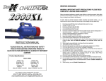
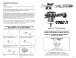
Congratulations!
TM
You’ve just purchased the Double K CHALLENGAIR AirMax Forced Air Dryer, which produces
warm, high velocity air under pressure to make your animal grooming tasks easier. Your new
dryer is designed to provide long, reliable service.
Please read this manual carefully and completely before beginning operation of your dryer and
keep this manual in a convenient and safe place for future reference.
TM
A warranty card is included with your dryer and should be filled out completely and mailed to
Double K Industries within 30 days of the purchase date of your dryer to validate your warranty.
Online registration available at www.DoubleKIndustries.com
Your CHALLENGAIR AirMax has a two year warranty covering the unit against defects in
materials and workmanship. Regular maintenance items such as brushes and filters are not
included (see warranty card for complete warranty information). It is also important to retain your
sales receipt as proof of purchase should service ever be needed.
Your CHALLENGAIR AirMax has two brush-type motors. It is important that the brushes be
changed when they become worn down to prevent damage to your dryer motor (brushes are
maintenance components and are not covered under the warranty). We suggest checking the
motors brushes after every 500 hours of dryer use. Please see section on BRUSHES in this
manual for instructions.
INSTRUCTION MANUAL
PLEASE READ ALL INSTRUCTION AND SAFETY
PRECAUTIONS BEFORE OPERATING PRODUCT!
SAVE FOR FUTURE REFERENCE, WARRANTY PERTINENT
CONTENT.
Product Specifications:
Model: AirMax
Voltage: 115v
Amperage: 16.4
Hertz: 60
Wattage: 1886
Horse Power: 3 each motor
Motor Air Volume: 123 CFM each
Voltage: 230v
Amperage: 5.8
Hertz: 50/60
Wattage: 1334
Horse Power: 3 each motor
Motor Air Volume: 123 CFM each
9711 Mason Avenue Chatsworth, CA 91311
(818) 772-2887 (800) 821-9449 Fax: (818) 886-0218
www.DoubleKIndustries.com [email protected]
8
A NOTE ABOUT HEAT: Your CHALLENGAIR AirMax has no heating element. The
CHALLENGAIR AirMax produces heat by a “flow-thru” motors system, meaning the air is pushed
through the motors and is warmed by the natural heat of the motors that occurs during operation.
This means greater electrical savings and efficiency for you. The dryer will reach its maximum air
temperature after about 2-4 minutes of operation. (Note: The higher the room temperature, the
warmer the air from the dryer will be.)
ASSEMBLY
To attach hose to dryer: Your dryer hose has a black hose adapter that will screw onto the hose in
a counter-clockwise motion. The adapter with hose attached then fits onto the dryer with a halftwist motion that locks the adapter onto the dryer.
First place the adapter over the snout of the dryer with the Double K logo facing up then turn hose
counter-clockwise until the adapter locks in place, the Double K logo should then be sitting
horizontally.
To remove hose from adapter: Turn the hose clockwise.
ATTACHMENTS: Your dryer is equipped with one hose and 4 twist-on nozzles. To attach nozzles
to hose, twist the nozzles “counter-clockwise”. Twist clockwise to remove.
OPERATION - Switches and Controls:
1. 2-Speed:
a. Low Speed / Standard Heat - Turn on the top motor switch.
b. High Speed / High Heat - Turn on both motor switches.
2. Variable Speed (optional)
a. Maximum Output - Turn the dial speed control clockwise to its maximum.
b. Variable Output: - Turn the dial speed control clockwise to desired air output.
c. Off Position - Turn the dial speed control counter-clockwise until it clicks off.
REQUIRED MAINTENANCE
IMPORTANT SAFEGUARDS
WARNING: IMPORTANT SAFETY PRECAUTIONS!! PLEASE READ
COMPLETELY BEFORE USING PRODUCT!!
When using electrical appliances, especially when children or animals are present, basic safety
precautions should always be followed to reduce the risk of fire, electric shock, and personal
injury, including but not limited to the following:
DO NOT TURN ON DRYER WITHOUT FIRST HOLDING THE DRYER HOSE, as the air volume
from the dryer can cause the hose to whip or move rapidly and may cause injury.
1.
2.
3.
4.
5.
6.
7.
8.
9.
10.
11.
12.
13.
14.
15.
16.
17.
18.
19.
20.
21.
2
Do not leave dryer OR the animal unattended while product is in use.
Unplug unit when not in use.
Do not use extension cords with dryer.
Do not unplug unit by pulling on cord.
Do not expose dryer to rain or water.
Do not use or store dryer where it can fall or be pulled into tub or sink or standing water. If
dryer falls into water . . . UNPLUG IT . . . Do not reach into the water!
Unplug unit before attempting any maintenance or service.
Do not put any object into dryer openings.
Keep loose clothing, jewelry and hair away from dryer openings.
Do not direct dryer air towards eyes or ears of people or pets.
Never use dryer if it has a damaged cord or plug, has been dropped, damaged or exposed
to rain or water. Return to Double K Industries or an Authorized Service Center for service.
This dryer should not be used as a cage dryer, for cage drying please consider our model
560 Cage dryer.
This product is for use on animals only.
Recommended operation by adults only. Use caution when working around children.
Do not use attachments not recommended by Double K Industries.
Do not operate without filters in place. Keep filters clean, as dirty filters limit air intake and
may damage the motor or cause overheating.
Plug only into a properly grounded receptacle. Always make sure the amperage of the
electrical outlet is sufficient for the amperage rating of the product. (See Product
Specifications for amperage rating of this product).
Do not use product for anything other than its intended purpose.
Do not attempt to perform any service or maintenance not outlined in instruction manual.
Do not attempt any product modifications or alterations. Do not use, if any parts or switches
are damaged. Send to an Authorized Service Center or Double K Industries for service.
When servicing, use only Double K Industries parts.
FILTERS:
(Procedures below must be performed regularly or as needed to protect dryer warranty status.)
FILTER CLEANING: Both the external and internal filters of the CHALLENGAIR AirMax should
be kept clean. If the filters become heavily coated with hair and/or dirt, it will reduce the air output
of your dryer and can cause damage to the motors or cause the motors to overheat.
*Never operate the dryer without all filters in place.
To clean external filter: Vacuum or shake off dirt and hair daily. Filter may be rinsed in water if
necessary. Let filter dry completely before reinstalling on dryer.
To clean the internal motor filter of the CHALLENGAIR AirMax:
1.
2.
3.
4.
5.
6.
7.
Unplug dryer.
Slide off the back cover of the dryer. This is a compression fit and will come off with a little
effort.
The internal filter is housed inside of a two piece frame. ( Pull on finger tab at the center of
filter frame to remove)
To remove the filter between the two frames: use a flat head screw driver to pry up or
release the six snap-in tabs around the edge of the filter frame.
Clean motor filter disk by vacuuming off hair and dirt, or wash filter gently in cool water.
Shake off excess water and allow to air dry completely. (Replace filter if necessary)
Reassemble the two piece filter frame and replace it onto the motor assembly housing by
pushing it into place.
Replace dryer back cover.
Any maintenance not explained in this manual should be performed by Double K Industries or an
Authorized Service Center. Call Double K Industries for the name of an Authorized Service
Center nearest you. All warranty service must be performed by an Authorized Service Center (or
Double K Industries) to protect your warranty status.
Attachment List
Attachment
P/N
Description
Qty.
825-6, 8, 10, 12
or 15
Hose 1½" Black on Blue
1
896
1½" Air Sweep Nozzle
1
897
1½" Regular Nozzle
1
2036
Hose to Dryer 1½" Locking Adapter
1
2068
1½"-¾" Hi-Velocity Nozzle
1
2070
Nozzle - Super Hi-Velocity
1
7
MODEL AIRMAX
EXPLODED DIAGRAM
15
23
17
22
16
13
21
14
2
24
Item #
1
2
3
4
5
20
18
13
25
19
6
26
5
7
8
27
9
9
10
11
10
12
11
12
8
1
Variable Speed Diagram
14
7
15
16
2
28
34
13
17
32
3
33
18
19
5
6
4
20
29
21
22
23
24
25
26
30
31
Speed Control
Board
2- SPEED WIRING
DIAGRAM
Blue
Black
White
Gray
Red
Triac PC Board
Black
#5539
MTR Black
#2
Green
Green
4
Red
Red #10101
#5537
#5537 Wire Nut
White #5512
27
Green
CORD
#881
Black
Black
#5539
Blue
Blue #806
#5537 Wire Nut
MTR
#2
White #5512
White
Green
Green
MTR
#1
Rear Motor Assy.
#2069
Switch #2148
#5537
MTR
#1
Black
CORD
Green #881
Black
Black
VARIABLE SPPED
WIRING DIAGRAM
Front Motor Assy.
#2069
Switch #2148
Green
#5539
28
29
30
31
32
33
34
Part #
2163
2123
2603
2148
2021
2157-1
2155-1
2120
2019
2065
2214
2119
2120
2108
2157-2
2155-2
483
2221
2222
2038
426
881
403
404
405
408
2159
5539
2160
2164
2177
2009
5538
2027
2049
2178
2069
2064
2606
2168
2145N
5509
2217
2153
2167
AIRMAX PARTS LIST
DESCRIPTION
Screw, 2600 Series Housing
Housing Plug (models w/o stand)
Decal, AirMax Switch Side
Switch Rocker 20A 125VAC 2-POS
10-24x3/8" Barrel Nut (Binding
Long Black Housing, Right Side
Long Blue Housing, Right Side
Spacer, Nylon Stand Off
Treaded Rod
Motor Brushes, 115v
Motor Brushes, 230v
Blue Terminal Flag 16-14ga
Spacer, Nylon Stand Off
Housing O-Ring for Hose Adapter
Long Housing, Left Side
Long Housing, Left Side
Bow Shackle
Decal, 115v AirMax
Decal, 230v AirMax
Strain Relief (14/3 cord)
7" 18 lb. Natural Nylon Quick Tie wrap
Assy. Cord set 115v
230v GB Cord set UK-Ireland
230v China Cord
230v Eur. Cord set Continental Europe
230v Aus Cord set New Zealand
Wire Grommet, 4-Hole
Nut, Orange Hard Plastic Wire
Silicone Rubber Molded Motor Mount 115v
Silicone Rubber Molded Motor Mount 230v
Internal Motor Filter Assy.
Sound Control Foam Disk
Velcro for External Filter
External Filter
End Cap Assembly (Includes 5538 and 2009)
Internal Filter Pack 3-Per
Motor 120v AirMax 5.1" Single Stage
Motor 230v AirMax 5.1" Single Stage
VS Decal, 115v Extreme, Product Data Side
Speed Control Board (115v)
Nut, Rheostat Speed Control - VS
Knob Switch Black
Deal VS Pot Side: Variable Speed Units
3/8 External-Tooth Lock Washer
Triac PC Board (115v), Assy. w/ Heat Sink
Qty.
12
2
1
2
2
1
1
1
4
4
1
1
1
2
1
1
1
1
2
4
2
1
1
1
1
1
1
2
1
1
1
1
1
1
1
Fig. 2 Top
Fig. 1 Side
Brush Assembly
Retainer (Ref # 2)
BRUSHES: Your CHALLENGAIR AirMax has two brush-type motors. The brushes should be
checked for wear after approximately 500 hours of use. If the carbon brushes are worn shorter
than 1/4 inch, the brushes should be replaced. Brushes may be ordered from Double K
Industries or an Authorized Service Center (you will need 2 sets, 1 set for each motor). Please
be sure to specify that your dryer is an AirMax, as the brushes are slightly different from one dryer
model to another.
To check and/or replace brushes:
1.
Unplug electrical cord from wall outlet.
Disassembly:
2.
3.
Motor Part
# 2069
Brush Assembly with
Metal Body (Ref # 1)
Brush Assembly
Retainer Screw (Ref # 3)
4.
5.
Fig. 3 Top
Down
6.
Brush Assembly with
Metal Body (Ref # 1)
Part #2065
Brush Assembly
Retainer (Ref # 2)
Brush Assembly
Retainer Screw
(Ref # 3)
Brush Retainer
Arm must slide into
the Male Terminal.
Slide off the back cover from the dryer. This is a compression fit and will come off with a
little effort.
Remove all screws on the outside of the dryer that hold the two halves of dryer housing in
place. It may be best to lay the dryer on its side while removing these screws.
Each motor will be sitting in place inside the rubber silicone motor mounts. Removing the
rubber silicone motor mounts from the motor is not necessary to replace brushes.
Disconnect the motor power wires.
Front motor:
a. Loosen the two brush assembly retainer screws (Fig. 3, Ref # 3) to loosen the
brush assembly retainer (Fig. 3, Ref # 2). Remove the brush assembly (Fig. 3,
Ref # 1) and replace it with a new one. (Note: IMPORTANT - the brush has a
small tab on the bottom that MUST be fitted into the slot on the motor frame for
proper positioning) (Fig. 3, Ref # 4)
b. After the new brush assembly is seated, tighten the brush assembly retainer
screws.
c. Repeat steps A-B for the brush on other side of motor.
Rear motor:
a. Follow steps A-C above, as outlined for the front motor.
Male Terminal
Reassembly:
7.
Brush
Assembly Tab
(Ref # 4)
8.
9.
6
Inspect the motor mounts for cracks or damage -- replace if necessary. Set the motors back
into their original positions in the dryer housing. Each motor mount has slots that fits over
corresponding alignment tabs on the inside of the dryer housing. These slots and tabs must
match up for proper fit and function. (Note: In the event that the motor mount is removed
from the motor, simply replace it by being mindful to align the contours of the motor mount
with corresponding contours on the motor housing.)
Reattach the screws around the outside of the dryer making sure the two halves are
matching up.
After the two halves of the dryer housing have been put together, replace motor filter on
back motor and push the burgundy back cover back onto the rear of the dryer. Replace
exterior filter on to burgundy back cover. Always make sure all filters are in place before
operating dryer.
3