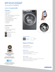
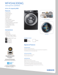
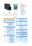
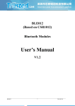
1
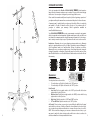
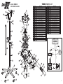
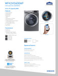
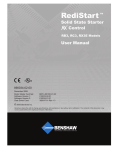
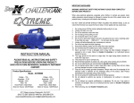
REQUIRED MAINTENANCE
FILTERS:
TM
TM
(The maintenance obligations below must be performed on a regular basis or as needed to
protect warranty status)
If the filters become heavily coated with hair and/or dirt, it will reduce the air output of your
dryer and can cause damage to the motors or cause the motors to overheat.
*Never operate the dryer without all filters in place.
Filter Cleaning: The top filter may be cleaned after each use by wiping away hair that is on
the filter. The filter must periodically be shaken out, or vacuumed off to remove excessive dirt,
hair and dander that is in the filter. The filter may also be washed with water and mild soap. Let
dry completely before installing back on the dryer. (Never run dryer without filter in place.)
Cleaning Dryer Interior: Dust will accumulate inside the dryer. Blow clean as needed using a
Challengair Forced Air Dryer or suitable high pressure air outlet.
Any maintenance not explained in this manual should be performed by Double K Industries,
or an Authorized Service Center. Call Double K Industries for the name of an Authorized
Service Center nearest you. All warranty service must be performed by an Authorized Service
Center (or Double K Industries) to protect your warranty status.
Instructions for Changing the Arm Extension Sleeve (PN 7046A)
and Arm Nozzle (PN 7007) on 9000 Series Dryers
*Use of Safety Gloves is advisable as internal metal components may have small burrs that can cut bare skin.
1
Carefully remove the Nozzle Retaining Screw (PN 845)
from your Dryer Assembly and put it aside.
2
Pull firmly on the Arm Nozzle (PN 7007) to disengage it
from the Arm Extension (PN 7045). Heating with hair
dryer may ease this process.
3
8
Pull firmly on the Arm Extension Sleeve (PN 7046A) to
remove it.
4
Push on the replacement Arm Extension Sleeve that is
included in your Arm Nozzle Replacement Kit.
5
Slide the replacement Arm Nozzle back over the Arm
Extension Sleeve.
6
Reinstall the Nozzle Retaining Screw. Drive the screw
until it contacts the metal groove underneath. Do not
over-tighten.
9000 II
INSTRUCTION MANUAL
PLEASE READ ALL INSTRUCTION AND SAFETY
PRECAUTIONS BEFORE OPERATING PRODUCT!
SAVE FOR FUTURE REFERENCE, WARRANTY
PERTINENT CONTENT.
Product Specifications:
Model - 9000 II
Voltage - 115v
Amperage - 16.08
Wattage - 1849.2
Hertz - 60
RPM - 3450
Horse Power - 1/3
Product Air Volume: 260CFM
9711 Mason Avenue, Chatsworth, CA 91311
(818) 772-2887 • (800) 821-9449 • fax: (818) 886-0218
www.DoubleKIndustries.com • [email protected]
10/2/12
IMPORTANT SAFEGUARDS
ASSEMBLY:
WARNING: IMPORTANT SAFETY PRECAUTIONS!! PLEASE READ
COMPLETELY BEFORE USING PRODUCT!!
Dryer and Stand
When using electrical appliances, especially when children or animals are present,
basic safety pre-cautions should always be followed to reduce the risk of fire, electric
shock, and personal injury, including, but not limited to the following:
1.
2.
3.
4.
5.
6.
7.
8.
9.
10.
11.
12.
13.
14.
15.
16.
17.
18.
Do not use product for anything other than its intended purpose.
Unplug unit when not in use.
Do not use extension cords with dryer.
Do not unplug unit by pulling on cord.
Do not expose dryer to rain or water.
Do not use or store dryer where it can fall or be pulled into tub or sink or standing water. If dryer falls into water . . . UNPLUG IT . . . Do not reach into the water!
Unplug unit before attempting any maintenance or service.
Do not put any object into dryer openings.
Keep loose clothing, jewelry and hair away from dryer openings.
Do not direct dryer air towards eyes or ears of people.
Never use dryer if it has a damaged cord or plug, has been dropped, damaged,
exposed to rain or water. Return to Double K Industries or an Authorized
Service Center for service.
Recommended operation by adults only. Use caution when working around
children.
Use only attachments recommended by Double K Industries.
Do not operate without filters in place. Keep filters clean, as dirty filters limit air
intake and may damage the motor or cause overheating.
Plug only into a properly grounded receptacle. Always make sure the amperage of the electrical outlet is sufficient for the amperage rating of the product.
(See Product Specifications for amperage rating of this product).
Do not attempt to perform any service or maintenance not outlined in instruction manual.
Do not attempt any product modifications or alterations. Do not use, if any
parts or switches are damaged - send to an Authorized Service Center or
Double K Industries for service.
When servicing, use only Double K Industries parts.
The stand tube assembly is pre-assembled and wrapped in paper. The stand tube
assembly is compressed and held in position by the center clamp. Loosen the handle
on the clamp and allow the spring to extend the tube assembly. Place the end of the
larger outer tube down into the center of the stand base. Twist and push down firmly
(see ref #55, 57). On the dryer head assembly, move the yoke to a 90-degree angle to
the dryer. Lift the dryer and position over the assembled stand and slide the tube of
the yoke into the upper stand tube (see ref #49, 53). With clamping handle still loose,
raise or lower dryer to desired height and tighten stand adjustment handle as
explained in the next paragraph (see ref #45).
Stand Height Adjustment and Dryer Angle Adjustment:
Your dryer has "ratchet" type adjustment handles on the stand and the dryer. To
tighten an adjustment handle, turn the handle clockwise as far as is comfortable. As
necessary, for additional tightening, pull the handle out to disengage the "ratchet"
and while keeping the handle pulled out, turn the handle counter-clockwise to a
suitable position for continued tightening. Release the handle to engage the
"ratchet" again and repeat these procedures until the adjustment handle is tight.
Reverse the turning direction of these actions to loosen an adjustment handle.
NOZZLE: The nozzle at the end of the extension arm may be rotated to change the
direction of the airflow. Simply rotate nozzle to the desired direction (see ref #42).
Dryer Stand: Your dryer stand has two locking casters to keep the dryer from rolling
inadvertently. To lock wheels, press down the small tab on the locking casters. To
unlock, lift up on tab (see ref #59). For long life and smoother operation, avoid rolling
casters through hair that has fallen on the floor.
Optional Attachment: A hose and nozzle kit is available for the Challengair 9000
Auto. To attach the hose to the dryer, insert hose end into the arm extension nozzle.
To attach nozzles to the hose, simply push nozzle securely onto the hose end.
Locking
Wheels
Minimum Airflow Position
Maximum Airflow Position
(View with Sound Cap removed to show lever position)
2
Unlocked
Locked
7
CONGRATULATIONS!
You’ve just purchased the Double K CHALLENGAIR 9000 II, which produces
large volumes of warm air under pressure to make all of your vehicle interior drying
tasks easier. Your new dryer is designed to provide long, reliable service.
Please read this manual carefully and completely before beginning operation of
your dryer and keep this manual in a convenient and safe place for future reference.
49
42
53
A warranty card is included with your dryer and should be filled out completely
and mailed to Double K Industries within 30 days of the purchase date of
yourdryer to validate your warranty. Online registration available at
www.DoubleKIndustries.com.
Your CHALLENGAIR 9000 II has a two year warranty covering the unit against
defects in materials and workmanship. Regular maintenance items such filters are
not included (see warranty card for complete warranty information). It is also important to retain your sales receipt as proof of purchase should service ever be needed.
Limitations - Warranty does not cover shipping or transportation costs. Warranty
applies to original purchaser only. Proof of date of purchase is required. Warranty is
void if registration card is not mailed within 30 days of purchase or delivery.
Warranty does not cover abuse, accidents, acts of war, dropped product, improper
voltage, disassembly or alteration. Disassembly, repair or service by anyone other
than Double K Industries or a Double K Industries authorized service center will void
the warranty.
56
45
55
LOW HEAT
MEDIUM HEAT
HIGH HEAT
OFF
Operation:
9000 AUTO
Switches and Controls:
Your dryer has three rocker switches.
To turn the dryer on: Flip the left switch to the “ON” position.
To turn the dryer off: Flip the left switch to the “OFF” position.
•
•
57
59
6
58
Heat Control:
Low Heat: Flip the top right switch to the “LOW” position while the bottom
right switch is in the off position.
Medium Heat: Flip the bottom right switch to the “MED” position while the top
right switch is in the off position.
High Heat: Flip both switches to “LOW” and “MED” position.
To Turn Off Heat: Flip both switches to the “OFF” position.
•
•
•
•
Air Control: The air volume on your dryer is controlled by the baffle wheel located
under the filter on the top of the dryer. Rotate the lever attached to the wheel clockwise to reduce the air and counterclockwise to increase the air volume (see ref #9).
NOTE: The heat will also change as you increase or decrease the air volume, so you
may want to adjust the heat setting together with the air volume to achieve the
desired combination of air temperature and volume.
3
TM
9000 II PARTS LIST
MODEL 9000 II
EXPLODED DIAGRAM
43
1
48
44
Item# Part#
DESCRIPTION
1
7020
Screw #8-16 x 5/8 Hi-Low PHP
2
7032
Sound Cap, 9000 AUTO
3
7049
9000 AUTO Sound Absorbing Disc
4
7029
9000 AUTO Air Intake Filter 5.8
5
9036
Screw, 6-32 x 5/8 Slot Pan M/S
6
5538
Velcro for Filter Material
7
7014
Washer, #10 1” OD Fender
8
7010
Louver Intake Air Control 9000 AUTO
9
7055
Secondary Louver Air Intake 9000 AUTO
10
2091
Rivet Aluminum 3/8 x 1/8”
11 7006-1
9000 AUTO Fan Housing Cut Out
12
5533
Nut, #6-32 UNF Locking Nylon Insert
13
7001
Inpeller Fan Blade
14
5531
Nut #10-32 UNF Locking Nylon Insert
15
877
Cable Tie 7” Flat Nylon Natural
16
7006
Housing, 9000 AUTO Motor & Fan
17
7019
Screw #10-32 UNF x 3/4 PHP
18
5532
Cable Clamp 3/8” Plastic Black
19
5533
Nut, #6-32 UNF Keps Locking Grade 2
20
7030
1/2# OD 3/8”L 1/4”ID Nylon Spacer
21
534
Cord Grommet
22
9036
Screw, 6-32 x 5/8 Slot Pan M/S Z
23
10019
Screw #6-32 UNF x 1/2 PHP Self-Tapping
24
881
Cordset 120v 14-Ft 14/3 SJTW
25
10109
9000 AUTO Motor Filter 5.13 DIA
26
7002
Motor 1/3 HP 3450 RPM
27
7051
Switch, 9000 AUTO Manual Reset
28
7004
Gasket, 9000 AUTO Manual Reset Switch
29
7009
Switch Box, 9000 AUTO
30
7034
Screw #10-16 x 3/4 Hi-Low PHP
31
7061
Label “On / Off” 9000 AUTO Switch
32
7017
Screw #10-16 x 1-1/2 Hi-Low PHP
33
2148 Switch Rocker 20A 125 VAC 2-Pos Black/Red
47
45
46
2
3
50
49
51
4
5
6
52
7
8
9
53
10
46
45
17
11
13
54
Qty.
12
1
1
1
1
1
1
1
1
1
1
4
1
6
1
1
2
3
3
2
1
2
1
1
1
1
1
1
1
2
1
2
3
Item#
34
35
36
37
38
39
40
41
42
43
44
45
46
47
48
49
50
51
52
53
54
55
56
57
58
59
Part#
7062
7044
10122
9003
7054
7045
443
7046A
7007
7015
7013
7033
10031
967
7031
7011
7048
7047
808
838A
7003
9020A
830-1
9023
9021
9022
DESCRIPTION
Label, 9000 AUTO Heat Control, Two-Switch
115v 9000 AUTO Element 1390 watt w/Fuse
Graphite Tape .015 x 1.0 x 50’
Screw #8 x 1/2 Sht, Metal PHP
Shield For Heating Element
9000 AUTO Arm Extension
Modified Screw #8
Sleeve, 9000 AUTO Arm Ext. 3”OD
Nozzle Directional, 9000 AUTO Arm
Bolt Screw 1/4-20 UNC x 1-1/4 Carriage
Washer, 1.0 ODx.378 IDx.030 THK
Handle Lever Adj. Black
Washer, 1/4 SAE Flat Pltd
Washer Split Lock 1/4”
Nut Acorn 1/4-20 UNC Zinc Plate
9000 AUTO Mounting Fork Black
Mounting Fork Spring Compression
1/2” Steel Ball, Mounting Fork
Nut 5/16-18 UNC Nickel Plated
Tube, 24” Inner Dryer Stand
Clamp Stand Height Adjust
Tube, 30” Outer Dryer Stand
Gas Spring 36”, Lift-O-Mat
Stand Base, 26” 5-Leg Black
Caster 50mm Twin Wheel
Caster 50mm Locking Twin Wheel
CORD
12
43
GREEN
14
#5539
21
22
25
34
30
31 32
39
37
40
41
33
HEAT
SWITCH
24
38
HEAT
SWITCH
57
29
WHITE
20
BLACK
BLACK
52
36
#5539
23
#5539
BLACK
19
35
ON / OFF
SWITCH
55
14
WHITE
MOTOR
18
16
BLACK
#5539
17
WHITE
15
14
56
Qty.
1
1
1
4
1
1
1
1
1
3
4
2
5
2
1
1
1
2
2
1
1
1
1
1
3
2
BLACK
BLACK
#5537
#5537
BLACK
BLACK
HEATING ELEMENT
59
58
4
58
59
26
27
28
42
5