1
����������������������������������������
��������������
Wire the controller communications E-Bus using level IV 22
AWG (Belden part number 9D220150) or plenum-rated level
IV 22 AWG (Belden part number 9H2201504) nonshielded,
twisted pair, solid conductor wire. When possible, use
Honeywell AK3781, AK3782, AK3791, or AK3792 cable (US
part numbers).
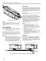
Pull the cable to each controller on the E-Bus and connect to
terminals 9 and 10.
The W7752 FCU Controller utilizes a free topology
transceiver (FTT10A) E-Bus which allows daisy-chain, loop,
and star network configurations or any combination thereof.
Depending upon the E-Bus configuration used, one or two
termination modules, part number 209541B, may be
required. Different connections to the termination module are
necessary depending upon whether it is used in a singly- or
doubly-terminated network configuration. See Excel 10
FTT/LPT 209541B Termination Module Installation
Instructions, form 95-7554.
��������������������������
�����
Input power provided must be 230 Vac (+10%, -15%), 50 or
60 Hz for W7752D and E; 115 Vac (+10%, -15%), 50 or
60 Hz for W7752F and G, and 100 Vac (±6%), 50 or 60 Hz
for W7752J.
������
— The E-Bus is insensitive to polarity, eliminating
installation errors due to miswiring.
— Do not bundle output wires with sensor, digital input or
communications bus wires. Maintain a minimum 3 in.
(76 mm) separation between E-Bus and Triac output
wiring.
— For installations, try to avoid areas of high
electromagnetic noise (EMI).
— Some T7770 Wall Modules used for 2000-series FCU
controllers have a daisy-chain connection for the E-Bus
to provide network access via built-in jack.
— For more information see E-Bus Wiring Guidelines, form
number 74-2865.
��������
Turn off power prior to connecting to or removing
connections from any terminals to avoid electrical
shock or equipment damage.
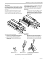
Use the heaviest gauge wire available, up to 14 AWG (2.5
2
2
mm ) with a minimum of 18 AWG (1.0 mm ) for all power
wiring. Strain relief/support must be provided for power wiring
within 2-3/8 in. (60 mm) of controller connection.
������������
���������
��������������������������������������������
��������������������������������������������������
��������������������������������������������������
������������������������������������������������
�������������������������������������������������
����������������������������������������������������
�����������������������������������������
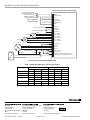
A variety of Excel 10 wall modules can be used with W7752
FCU Controllers. See T7460 Wall Modules Installation
Instructions, form number 95-7610; T7560 Digital Wall
Module Installation Instructions, form number 95-7620; and
T7770 Wall Modules Installation Instructions, form number
95-7538 for installation details.
W7752 FAN COIL UNIT CONTROLLER
W7752 FAN COIL UNIT CONTROLLER
9 10 11 12
9 10 11 12
TERMINATION
MODULE
��������������������������������������������������������������������������
95-7519-3
2