1
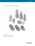
www.swagelok.com High-Pre s sure Fit tings Fe ature s ■ Pressures to 60 000 psi (4134 bar) ■ Weep holes for instant leak detection 2 High-Pressure Fittings Features ■ Fittings are machined from 316 stainless steel. ■ Back ferrule is manufactured from S17400 hardened stainless steel to ensure a secure grip on hardened or annealed tubing. ■ Weep holes allow instant leak detection. Weep hole ■ Unique ferrule action helps prevent excessive deformation of the seal area of tube end and body. ■ Fitting does not reduce tube wall thickness. ■ Fittings can be made, disconnected, and remade easily to provide a reliable leak-tight seal. Bleed slot ■ Bleed slot on male thread connectors facilitates purging of fluid before operation. Pressure Ratings High-Pressure Fitting ■ The rating for high-pressure tube fittings and threaded connectors is determined with Swagelok® hardened tubing at room temperature. ■ The rating for high-pressure tube fittings and threaded connectors with annealed tubing is 30 000 psig (2067 bar) at room temperature. Pipe Fitting Materials of Construction Component Material Back ferrule S17400 SS All other components 316 SS ■ Pipe thread pressure rating is based on laboratory testing with both male and female threads manufactured by Swagelok Company. Ordering Information and Dimensions Dimensions are for reference only and are subject to change. High-Pressure Tube Fitting to High-Pressure Male Thread Connectors F flat Bleed slot G Tube OD in. 1/4 3/8 E D A High-Pressure Tube Fitting to High-Pressure Female Thread Connectors F flat G D E A Uniform Thread Size Ordering Number A 9/16-18 SS-440-1-44M 1.96 (49.8) 3/4-16 SS-440-1-64M 2.32 (58.9) 9/16-18 SS-640-1-44M 2.24 (56.9) 3/4-16 SS-640-1-64M 2.41 (61.2) Dimensions, in. (mm) D E 0.82 (20.8) 0.09 (2.3) 1.04 (26.4) 0.09 (2.3) 0.12 (3.0) 0.12 (3.0) F 5/8 13/16 G 3/4 13/16 15/16 3/4-16 SS-940-1-64M 3.01 (76.5) 1 1/8-12 SS-940-1-94M 3.19 (81.0) Tube OD in. Uniform Thread Size Ordering Number F G 1/4 9/16-18 SS-440-7-44F 1.87 (47.5) 0.82 (20.8) 0.09 (2.3) 7/8 3/4 3/8 3/4-16 SS-640-7-64F 2.26 (57.4) 1.04 (26.4) 0.12 (3.0) 1 1/8 15/16 9/16 1 1/8-12 SS-940-7-94F 3.13 (79.5) 1.45 (36.8) 0.19 (4.8) 1 3/8 1 3/8 9/16 1.45 (36.8) 0.19 (4.8) 1 1/4 D E 60 000 (4134) 1 3/8 Dimensions, in. (mm) A Pressure Rating psig (bar) Pressure Rating psig (bar) 60 000 (4134) High-Pressure Fittings Ordering Information and Dimensions Dimensions are for reference only and are subject to change. Unions F flat G E A D Reducing Unions G T TxGx E A Ordering Number 1/4 SS-440-6 2.25 (57.2) 0.82 (20.8) 0.09 (2.3) 3/8 SS-640-6 2.70 (68.6) 1.04 (26.4) 0.12 (3.0) 13/16 15/16 9/16 SS-940-6 3.69 (93.7) 1.45 (36.8) 0.19 (4.8) 1 1/4 Tube OD, in. F flat D Tube OD in. Dimensions, in. (mm) A T Tx Ordering Number 3/8 1/4 SS-640-6-440 1/4 SS-940-6-440 9/16 Dx 3/8 SS-940-6-640 Bulkhead Unions F flat G E A D D Union Elbows F flat G E D Tube OD in. Ordering Number 1/4 SS-440-61 3/8 SS-640-61 D E F G 5/8 3/4 60 000 (4134) 1 3/8 Dimensions, in. (mm) A 2.61 D 1.04 Dx 0.82 E 0.09 (66.3) (26.4) (20.8) (2.3) 0.82 0.09 (81.8) 1.45 (20.8) (2.3) 3.42 (36.8) 1.04 0.12 (26.4) (3.0) 3.22 (86.9) Dimensions in. (mm) A 3.30 D 0.82 E 0.09 (83.8) (20.8) (2.3) 3.72 1.04 0.12 (94.5) (26.4) (3.0) 5.07 1.45 0.19 (129) (36.8) (4.8) F G 15/16 3/4 1 1/16 15/16 1 5/8 1 3/8 F G 1 1/4 1 3/8 F flat G Pressure Rating psig (bar) 0.91 0.50 60 000 (23.1) (12.7) (4134) (19.8) 1.34 Ordering Number F G 1/4 SS-440-9 1.39 (35.3) 0.82 (20.8) 0.09 (2.3) 11/16 3/4 3/8 SS-640-9 1.74 (44.2) 1.04 (26.4) 0.12 (3.0) 7/8 15/16 9/16 SS-940-9 2.52 (64.0) 1.45 (36.8) 0.19 (4.8) 1 1/4 1 3/8 Tube OD in. Ordering Number F G 1/4 SS-440-3 2.78 (70.6) 0.82 (20.8) 0.09 (2.3) 11/16 3/4 3/8 SS-640-3 3.48 (88.4) 1.04 (26.4) 0.12 (3.0) 7/8 15/16 9/16 SS-940-3 5.04 (128) 1.45 (36.8) 0.19 (4.8) 1 1/4 1 3/8 (34.0) Dimensions, in. (mm) E D D A Dimensions, in. (mm) A D E (4134) Panel Thickness Max in. (mm) Hole Drill Size 0.78 Pressure Rating psig (bar) 60 000 (4134) A Union Tees 60 000 15/16 Tube OD in. E Pressure Rating psig (bar) 3/4 3/4 SS-940-61 D Gx 13/16 15/16 9/16 A Pressure Rating psig (bar) Pressure Rating psig (bar) 60 000 (4134) 3 4 High-Pressure Fittings Ordering Information and Dimensions Dimensions are for reference only and are subject to change. High-Pressure Male Thread Unions F flat Bleed slot Bleed slot Uniform Thread Size Ordering Number 9/16-18 SS-44M-6 Pressure Rating psig (bar) 60 000 Dimensions, in. (mm) A 1.71 E 0.09 (43.4) (2.3) F 5/8 (4134) E A High-Pressure Male Thread to Coned Tube Stub Adapters Tube OD in. Uniform Thread Size Ordering Number 1/4 9/16-18 SS-44M-A-441 2.01 (51.1) 1.00 (25.4) 0.06 (1.5) 3/8 3/4-16 SS-64M-A-641 2.47 (62.7) 1.25 (31.8) 0.12 (3.0) 13/16 60 000 (4134) 9/16 1 1/8-12 SS-94M-A-941 3.34 (84.8) 1.76 (44.7) 0.19 (4.8) 1 1/4 F flat Bleed slot E Port Connectors E Caps F flat 1/4 SS-441-PC 1.85 (47.0) 0.50 (12.7) 0.06 (1.5) 60 000 (4134) 3/8 SS-641-PC 2.33 (59.2) 0.68 (17.3) 0.12 (3.0) 60 000 (4134) 9/16 SS-941-PC 3.41 (86.6) 1.06 (26.9) 0.19 (4.8) 45 000 (3100) Tube OD in. Ordering Number 1/4 SS-440-C 1.35 (34.3) 0.82 (20.8) 0.09 (2.3) 3/8 SS-640-C 1.80 (45.7) 1.04 (26.4) 0.12 (3.0) 13/16 15/16 9/16 SS-940-C 2.52 (64.0) 1.45 (36.8) 0.19 (4.8) 1 1/4 Tube OD in. Ordering Number Dimensions, in. (mm) A G 1/4 SS-440-P 0.95 (24.1) 3/4 3/8 SS-640-P 1.18 (30.0) 15/16 9/16 SS-940-P 1.66 (42.2) 1 3/8 G E Plugs G A Tube OD in. G A E Ordering Number A Nuts D Tube OD in. D A A 5/8 60 000 (4134) 45 000 (3100) D A D F Pressure Rating psig (bar) Dimensions, in. (mm) Ordering Number Dimensions in. (mm) A G Pressure Rating psig (bar) Dimensions, in. (mm) A D E Dimensions, in. (mm) A Front Ferrules D E F G 5/8 3/4 1 3/8 Pressure Rating psig (bar) 60 000 (4134) Pressure Rating psig (bar) 60 000 (4134) Tube OD in. Ordering Number 1/4 SS-443-1 Back Ferrules Tube OD in. Ordering Number 1/4 174PH-444-1 1/4 SS-442-1 0.81 (20.6) 3/8 SS-642-1 0.97 (24.6) 15/16 3/8 SS-643-1 3/8 174PH-644-1 SS-942-1 1.44 (36.6) 1 3/8 9/16 SS-943-1 9/16 174PH-944-1 9/16 3/4 High-Pressure Fittings Ordering Information and Dimensions Dimensions are for reference only and are subject to change. High-Pressure Tube Fitting to Male Pipe Thread Connectors F flat G D Male NPT Size in. Ordering Number 1/4 1/4 SS-440-1-4 1.84 (46.7) 0.82 (20.8) 0.09 (2.3) 3/8 3/8 SS-640-1-6 2.09 (53.1) 1.04 (26.4) 0.12 (3.0) 13/16 15/16 9/16 1/2 SS-940-1-8 2.80 (71.1) 1.45 (36.8) 0.19 (4.8) 1 1/4 Tube OD in. Male NPT Size in. Ordering Number F G 1/4 1/4 SS-440-2-4 1.50 (38.1) 0.82 (20.8) 0.09 (2.3) 7/8 3/4 3/8 3/8 SS-640-2-6 1.74 (44.2) 1.04 (26.4) 0.12 (3.0) 7/8 15/16 9/16 1/2 SS-940-2-8 2.52 (64.0) 1.45 (36.8) 0.19 (4.8) 1 1/4 1 3/8 Tube OD in. Female NPT Size in. Ordering Number F G 1/4 1/4 SS-440-7-4 2.07 (52.6) 0.82 (20.8) 0.09 (2.3) 7/8 3/4 3/8 3/8 SS-640-7-6 2.36 (59.9) 1.04 (26.4) 0.12 (3.0) 1 15/16 9/16 1/2 SS-940-7-8 2.99 (75.9) 1.45 (36.8) 0.19 (4.8) 1 1/4 1 3/8 A F flat G A D E F G 5/8 3/4 1 3/8 Pressure Rating psig (bar) 30 000 (2067) Dimensions, in. (mm) A D E Pressure Rating psig (bar) 30 000 (2067) E D High-Pressure Tube Fitting to Female Pipe Thread Connectors F flat G Dimensions, in. (mm) A D E Pressure Rating psig (bar) 20 000 (1378) E A High-Pressure Tube Fitting to Swagelok Tube Fitting Unions F flat Tube OD, in. Dx T Tx Ordering Number 1/4 1/8 SS-440-6-200 Tx 3/8 G T D A 9/16 E High-Pressure Tube Fitting to Coned Tube Stub Reducers 1/4 3/8 Tube OD, in. F flat SS-640-6-400 SS-940-6-600 T Tx Ordering Number 1/4 3/8 SS-440-R-641 E1 Tx GT D Dimensions, in. (mm) E A High-Pressure Tube Fitting to Male Pipe Thread Elbows D Tube OD in. E 3/8 9/16 A 9/16 3/8 SS-640-R-941 SS-940-R-641 Dimensions, in. (mm) A 1.88 D 0.82 Dx 0.50 E 0.09 (47.8) (20.8) (12.7) (2.3) 2.21 1.04 0.60 0.12 (56.1) (26.4) (15.2) (3.0) 2.80 1.45 0.66 0.19 (71.1) (36.8) (16.8) (4.8) F G 5/8 3/4 13/16 1 1/4 15/16 1 3/8 Dimensions, in. (mm) A 2.53 D 0.82 E 0.09 E1 0.12 (64.3) (20.8) (2.3) (3.0) 3.28 1.04 0.12 0.19 (83.3) (26.4) (3.0) (4.8) 3.31 1.45 0.19 0.12 (84.1) (36.8) (4.8) (3.0) F G 5/8 3/4 13/16 1 1/4 15/16 1 3/8 Pressure Rating psig (bar) 10 900 (751) 10 200 (702) 7 500 (516) Pressure Rating psig (bar) 60 000 (4134) 45 000 (3100) 60 000 (4134) 5 6 High-Pressure Fittings Ordering Information and Dimensions Dimensions are for reference only and are subject to change. Coned Tube Stub to Male Pipe Thread Adapters F flat E Tube OD in. Male NPT Size in. Ordering Number Pressure Rating psig (bar) 1/4 1/4 SS-441-A-4 1.84 (46.7) 0.06 (1.5) 9/16 3/8 3/8 SS-641-A-6 2.12 (53.8) 0.12 (3.0) 11/16 9/16 1/2 SS-941-A-8 2.85 (72.4) 0.19 (4.8) 7/8 Dimensions, in. (mm) A E F 30 000 (2067) A Coned Tube Stub to Swagelok Tube Fitting Adapters Tube OD, in. F flat T Tx Ordering Number 1/4 1/4 SS-441-A-400 E Tx G T D A High-Pressure Male Thread to Male Pipe Connectors F flat E A SS-641-A-600 SS-941-A-810 D 0.60 E 0.06 (50.0) (15.2) (1.5) 2.31 0.66 0.12 (58.7) (16.8) (3.0) 2.96 0.90 0.19 (75.2) (22.9) (4.8) F G 1/2 9/16 5/8 (702) 7 500 11/16 13/16 (516) 6 700 1/2 7/8 Thread Size Male NPT Size in. Ordering Number 9/16-18 1/4 SS-44M-1-4 1.55 (39.4) 0.56 (14.2) 0.09 (2.3) 5/8 3/4-16 3/8 SS-64M-1-6 1.78 (45.2) 0.56 (14.2) 0.12 (3.0) 13/16 1 1/8-12 1/2 SS-94M-1-8 2.30 (58.4) 0.75 (19.0) 0.19 (4.8) 1 1/4 Thread Size Female NPT Size in. Ordering Number 9/16-18 1/4 SS-44M-7-4 1.66 (42.2) 0.09 (2.3) 7/8 3/4-16 3/8 SS-64M-7-6 1.94 (49.3) 0.12 (3.0) 1 1 1/8-12 1/2 SS-94M-7-8 2.48 (63.0) 0.19 (4.8) 1 1/4 (461) Pressure Rating psig (bar) Dimensions, in. (mm) A D E F 30 000 (2067) D High-Pressure Male Thread to Female Pipe Connectors F flat Bleed slot 3/8 A 1.97 9/16 S-PH-0076-DM SNO-TRIK THREAD TO MALE PIPE CONNECTOR CUTAWAY-MS-02-160 Bleed slot 3/8 Pressure Rating psig (bar) 10 200 Dimensions, in. (mm) Dimensions, in. (mm) A E F Pressure Rating psig (bar) 20 000 (1378) E A High-Pressure Male Thread to Swagelok Tube Fitting Adapters F flat Bleed slot Tube OD in. Thread Size Ordering Number 1/8 9/16-18 SS-44M-A-200 1/4 9/16-18 SS-44M-A-400 G E A D 3/8 1/2 3/4-16 1 1/8-12 SS-64M-A-600 SS-94M-A-810 Dimensions, in. (mm) A 1.61 D 0.50 E 0.09 (40.8) (12.7) (2.3) 1.70 0.60 0.09 (43.1) (15.2) (2.3) 1.97 0.66 0.12 (50.0) (16.7) (3.0) 2.41 0.90 0.19 (61.2) (22.9) (4.8) F G 5/8 7/16 5/8 13/16 1 1/4 9/16 11/16 7/8 Pressure Rating psig (bar) 10 900 (751) 10 200 (702) 7 500 (516) 6 700 (461) High-Pressure Fittings 7 Ordering Information and Dimensions Dimensions are for reference only and are subject to change. High-Pressure Male Thread to Tube Socket Weld Adapters SNO-TRIK THREAD TO TUBE WELD ADAPTER CUTAWAY-MS-02-160 S-PH-0075-DM F flat Bleed slot T Tx E A D Tube OD, in. T Tx Thread Size 1/4 1/2 9/16-18 3/8 1/2 5/8 3/4 3/4-16 1 1/8-12 Ordering Number SS-44M-A-4TSW SS-64M-A-6TSW SS-94M-A-8TSW Dimensions, in. (mm) A 1.30 D 0.28 E 0.09 (33.0) (7.1) (2.3) 1.60 0.31 0.12 (40.6) (7.9) (3.0) 1.99 0.38 0.19 (50.5) (9.7) (4.8) F 5/8 13/16 1 1/4 Pressure Rating psig (bar) 20 000 (1378) 20 000 (1378) 15 000 (1033) Instructions for High-Pressure Cone and Ferrule Tube Fittings Installation—Hardened Tubing Installation—Port Connectors The pre-setting tool (see page 8) must be used for 1.Remove the nut and ferrules from the first of the two high-pressure tube fitting ports to be connected. Discard the ferrules. proper initial installation of high-pressure tube fittings with hardened tubing. 1.Install the nut and ferrules onto the pre-setting tool. 2.Insert the coned tubing into the pre-setting tool. 3.Make sure that the tubing rests firmly on the tapered shoulder of the pre-setting tool body. 4.Tighten the nut until the tubing cannot be turned by hand. 5.Mark the nut at the 6 o’clock position. 6.While holding the pre-setting tool steady, tighten the nut one and one-fourth turns to the 9 o’clock position. 7.Loosen the nut and remove the tubing with pre-set ferrules from the pre-setting tool. 8.Insert tubing with pre-set ferrules into the fitting body until the front ferrule seats; rotate the nut finger-tight. 9.While holding fitting body steady, tighten the nut threeeighths turn for 3/8 and 9/16 in. tubing and one-fourth turn for 1/4 in. tubing. Installation—Annealed Tubing 2.Slip the nut over the short end of the port connector. See illustration, port 1. Port 1 Port 2 3.Remove the nut and ferrules from port 2 and install them onto the pre-setting tool. 4.Insert the long end of the port connector into the presetting tool, making sure that it rests firmly on the tapered shoulder of the tool body. 5.Tighten the nut until the port connector cannot be turned by hand. 6.Mark the nut at the 6 o’clock position. 7.While holding the pre-setting tool steady, tighten the nut one and one-fourth turns to the 9 o’clock position. 8.Loosen the nut and remove the port connector end with pre-set ferrules from the pre-setting tool. The pre-setting tool is suggested for proper installation of high-pressure tube fittings with annealed tubing. When the pre-setting tool is used, use the instructions for hardened tubing. When the pre-setting tool is not used, use the following instructions: 9.Insert the port connector end with pre-set ferrules into port 2 until the front ferrule seats; rotate the nut finger-tight. 1.Insert coned tubing into the tube fitting. 11.Tighten the first nut onto port 1 finger-tight. 2.Make sure that the tubing rests firmly on the tapered shoulder of the tube fitting body. 12.While holding fitting body steady, tighten the nut threeeighths turn for 3/8 and 9/16 in. tubing and one-fourth turn for 1/4 in. tubing. 3.Tighten the nut until the tubing cannot be turned by hand. 4.Mark the nut at the 6 o’clock position. 5.While holding fitting body steady, tighten the nut one and one-fourth turns to the 9 o’clock position. 10.While holding fitting body steady, tighten the nut threeeighths turn for 3/8 and 9/16 in. tubing and one-fourth turn for 1/4 in. tubing. Reassembly Instructions You may disassemble and reassemble a Swagelok highpressure tube fitting. Installation—High-Pressure Male and Female Threads 1.Insert tubing with pre-set ferrules into the fitting body until the front ferrule seats; rotate the nut finger-tight. 1.Rotate the nut finger-tight. 2.While holding fitting body steady, tighten the nut threeeighths turn for 3/8 and 9/16 in. tubing and one-fourth turn for 1/4 in. tubing. 2.Tighten the nut one-eighth turn. Options and Accessories Pre-Setting Tool Visual Tube Inspection The pre-setting tool is suggested for initial assembly of Swagelok highpressure tube fittings when used with annealed tubing. The pre-setting tool must be used for initial assembly of these tube fittings when used with Swagelok hardened tubing. ■ A proper cone has ends that are faced and smooth. Tube OD/ Tool Size, in. Ordering Number ■ The cone should be free of any scratches and leave-off marks. Tube Preparation T, in. Minimum OD Required, in. 1/4 1/8 3/8 7/32 9/16 9/32 1/4 MS-440-PT 0.250 3/8 MS-640-PT 0.375 9/16 MS-940-PT 0.562 T N, in. 56° to 59° N For tubing tolerance requirements, contact your authorized Swagelok sales and service representative. Pre-Coned Tubing Pre-coned tube lengths of hardened or annealed tubing are available from 2 to 120 in. (5 to 305 cm) in length. Tube lengths are precisely coned with a high-quality finish. Annealed tubing is rated to 30 000 psig (2067 bar). Hardened tubing is rated to 60 000 psig (4134 bar). Coning Tool High-pressure tubing used with Swagelok high-pressure tube fittings should be prepared with a Swagelok coning tool. The Swagelok coning tool cuts a smooth, concentric cone on the tube end to help ensure reliable sealing in the fitting body. It is designed to prepare 1/4, 3/8, and 9/16 in. outside diameter heavy wall tubing. Tube OD in. Length in. (cm) Ordering Numbers Hardened Annealed Tubing Tubing 2 (5.0) SS-483-T-2 SS-483-A-2 Wall Thickness in. (mm) 4 (10.2) SS-483-T-4 SS-483-A-4 0.083 8 (20.3) SS-483-T-8 SS-483-A-8 (2.1) 12 (30.5) SS-483-T-12 SS-483-A-12 4 (10.2) SS-495-T-4 SS-495-A-4 8 (20.3) SS-495-T-8 SS-495-A-8 Ordering number: MS-469-CT 12 (30.5) SS-495-T-12 SS-495-A-12 For operating instructions, see the Coning Tool User’s Manual, MS‑CRD-CONING. 3 (7.6) SS-612-T-3 SS-612-A-3 4 (10.2) SS-612-T-4 SS-612-A-4 0.125 8 (20.3) SS-612-T-8 SS-612-A-8 (3.2) Each coning tool comes in a carrying case with Rapid Tap™ cutting lubricant; 1/4, 3/8, and 9/16 in. collets and tool bits; and inside-diameter deburring tool. Replacement Parts To order additional items separately, select an ordering number. Description Ordering Number Cutting lubricant MS-469CT-LUBE 1/4 in. collet MS-469CT-2-4 1/4 in. tool bit MS-469CT-7-4 3/8 in. collet MS-469CT-2-6 3/8 in. tool bit MS-469CT-7-6 9/16 in. collet MS-469CT-2-9 9/16 in. tool bit MS-469CT-7-9 Deburring tool MS-44CT-27 Safe Product Selection When selecting a product, the total system design must be considered to ensure safe, trouble-free performance. Function, material compatibility, adequate ratings, proper installation, operation, and maintenance are the responsibilities of the system designer and user. Caution: Do not mix or interchange parts with those of other manufacturers. 1/4 3/8 9/16 12 (30.5) SS-612-T-12 SS-612-A-12 4 (10.2) SS-918-T-4 SS-918-A-4 8 (20.3) SS-918-T-8 SS-918-A-8 12 (30.5) SS-918-T-12 SS-918-A-12 0.095 (2.4) 0.187 (4.7) Dimensions are for reference only and are subject to change. Warranty Information Swagelok products are backed by The Swagelok Limited Lifetime Warranty. For a copy, visit swagelok.com or contact your authorized Swagelok representative. Swagelok—TM Swagelok Company Rapid Tap—TM Relton Corporation © 2002–2010 Swagelok Company Printed in U.S.A., GLI August 2010, R4 MS-01-34