1
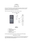
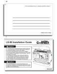
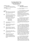
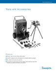
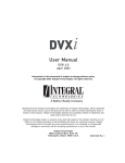
www.swagelok.com
Tubing Tools and Acce ssorie s
Products
■ Electric, bench top, and hand tube benders
■ Tube preparation tools
■ Tube support systems
2
Tubing Tools and Accessories
Contents
Tube Benders
Electric . . . . . . . . . . . . . . . . . . 2
Bench Top . . . . . . . . . . . . . . . 3
Tube Benders
Swagelok® benders provide high-quality bends on fractional and metric tubing
made from materials that can be used with Swagelok tube fittings. These easyto-use tube benders reduce installation time and effort as well as the potential for
wrinkling or other damage to the tubing during bending.
Electric Tube Benders
Features
Hand . . . . . . . . . . . . . . . . . . . . 5
■ Electronic control
Tube Preparation Tools
■ 1 to 110° bending range
Tube Cutter . . . . . . . . . . . . . . . 6
■ 1 to 2 in. outside diameter (0.049
to 0.220 in. wall thickness) and 25
to 50 mm outside diameter (1.2 to
5.0 mm wall thickness) tubing range
Tube Sawing Guide . . . . . . . . 6
Tube Deburring Tools . . . . . . . 6
■ One bend shoe for 1, 1 1/4, 1 1/2,
and 2 in. sizes
Tube Gripper Pad . . . . . . . . . . 6
■ One bend shoe for 25, 32, 38, and
Tube Support Systems
50 mm sizes
■ CE compliant
Bolted Plastic
Clamp Supports . . . . . . . . . . . 7
Technical Data
■ Dimensions—vertical position:
Cushioned Clamp
44 in. (112 cm) high, 29 in. (74 cm)
Tube Supports . . . . . . . . . . . 11
wide, 30 in. (76 cm) deep
P Clamp Supports . . . . . . . . 11
Tube Support Strips . . . . . . . 12
■ Weight—420 lb (191 kg)
■ Power requirements
See the Swagelok Electric Tube
Bender User’s Manual, MS‑13‑138,
for complete setup and operating
instructions.
MS-TBE-1—115 V (ac), 50/60 Hz;
maximum current—13 A
MS-TBE-2—230 V (ac), 50/60 Hz;
maximum current—7 A
See Ordering Information, page 4.
Tubing Data
Minimum tube length, bend radius, and wall thickness limits required to make a 90°
bend in annealed tubing are listed below. See Swagelok Tubing Data, MS‑01‑107,
for suggested tubing wall thickness for use with Swagelok tube fittings.
Fractional Tubing
Tube
OD
Min
Tube
Length
Approx
Bend
Radius
1
20.5
4
0.049/0.120
0.065/0.120
1 1/4
22.8
5
0.065/0.180
0.083/0.156
1 1/2
25.5
6
0.083/0.220
0.090/0.188
2
32.0
8
0.095/0.220
0.109/0.188
Approx
Bend
Radius
Carbon Steel
Wall Thickness, Min/Max
Carbon Steel
Stainless Steel
Dimensions, in.
Metric Tubing
Tube
OD
Min
Tube
Length
Wall Thickness, Min/Max
Stainless Steel
Dimensions, mm
25
520
103
1.2/3.0
1.8/3.0
32
582
126
2.0/4.0
2.0/4.0
38
648
152
2.2/4.5
2.2/4.5
50
810
203
—
3.0/5.0
Tubing Tools and Accessories
3
Tube Benders
Bench Top Tube Benders
Features
■ Rugged, lightweight aluminum construction
■ 1 to 180° bending range
■ 1/4 to 1 1/4 in. outside diameter (0.028 to 0.120 in. wall
thickness) and 12 to 30 mm outside diameter (1.0 to
3.0 mm wall thickness) tubing range
■ Steel bend shoes required for:
■1 in. outside diameter tubing with greater than 0.095 in.
Manual Model
wall thickness
■25 mm tubing with greater than 2.4 mm wall thickness
■all sizes of SAF 2507™ tubing
■all sizes of heavy-wall annealed stainless steel tubing
■all sizes of cold-drawn 1/8-hard stainless steel seamless
tubing.
■ Includes grease gun and metal carrying case for storage
■ Manual model can be operated with a 1/2 in. drill motor
Electric Model
using optional torque clutch and support arm.
■ CE compliant
Technical Data
Tubing Data
■ Dimensions—tube bender in case:
Minimum tube length, bend radius, and wall thickness limits required to make a 90°
bend in annealed tubing are listed below. See Swagelok Tubing Data, MS-01-107,
for suggested tubing wall thickness for use with Swagelok tube fittings.
14 1/2 in. (37 cm) high, 21 in. (53 cm)
wide, 11 in. (28 cm) deep
■ Weight—tube bender in case,
excluding tools:
Fractional Tubing
Manual model—75 lb (34 kg)
Electric model—79 lb (36 kg)
■ Power requirements (electric model)
MS-BTB-1—110 V (ac), 50/60 Hz;
maximum current—10 A
MS-BTB-2—230 V (ac), 50/60 Hz;
maximum current—5 A
See Ordering Information, page 4,
and Options and Accessories,
page 5.
Tube
OD
Min
Tube
Length
Approx
Bend
Radius
Wall Thickness, Min/Max
Stainless
Heavy-Wall Cold-Drawn
Steel
Annealed SS 1/8-Hard SS
Carbon
Steel
Dimensions, in.
1/4
3/8
0.028/0.065
7.00
1.4
0.035/0.065
1/2
0.035/0.083
0.035/0.083
5/8
8.50
1.8
0.035/0.095
3/4
9.75
2.2
7/8
10.5
2.6
1
12.2
3.2
0.049/0.120
0.065/0.120
1 1/4
15.0
4.4
0.065/0.120
0.083/0.120
0.065/0.095
0.028/0.065
0.083/0.134
0.035/0.083
0.083/0.188
0.049/0.109
0.049/0.095
0.049/0.109
—
Metric Tubing
Tube
OD
Min
Tube
Length
Approx
Bend
Radius
Wall Thickness, Min/Max
Carbon Steel
Stainless Steel
Dimensions, mm
12
15
16
18
20
178
216
248
36
46
1.0/2.5
1.0/2.2
1.2/2.5
67
1.2/2.8
267
67
25
311
82
381
112
28
1.0/2.0
1.0/2.2
55
22
30
1.0/2.2
1.2/2.8
1.2/3.0
1.8/3.0
1.8/3.0
2.0/3.0
4
Tubing Tools and Accessories
Tube Benders
Ordering Information, Electric and Bench Top Tube Benders
1. Select a basic ordering number.
Bender Type
4.Add a tool kit designator.
Ordering Number
Tool Kit
Electric
115 V (ac)
MS-TBE-1
230 V (ac)
MS-TBE-2
Electric
Fractional bend shoe, roller towers,
and tube clamps (1, 1 1/4, 1 1/2, and 2 in.)
Metric bend shoe, roller towers,
and tube clamps (25, 32, 38, and 50 mm)
Bench Top
Manual
MS-BTB-M
Electric—110 V (ac)
MS-BTB-1
Electric—230 V (ac)
MS-BTB-2
Bench Top
Aluminum fractional bend shoes and steel
rollers (1/2, 5/8, 3/4, 7/8, and 1 in.)
Aluminum metric bend shoes and steel
rollers (12, 16, 18, 20, 22, and 25 mm)
Example: MS-BTB-1
North
America
Japan/
Taiwan
United
Kingdom
Voltage
110/120 V (ac)
50/60 Hz
Plug
Type
NEMA
5-15
220/240 V (ac)
50/60 Hz
110/120 V (ac)
50/60 Hz
NEMA
6-15
NEMA
5-15
220/240 V (ac) NEMA
50/60 Hz
L6-20
110/120 V (ac)
IEC-309
50/60 Hz
220/240 V (ac)
BS 1363
50/60 Hz
Cord/
Wire
Type
Power
Cord
Designator
-1
AWG/ SJT
-2
-3
-4
-5
Harmonized
-6
Continental 220/240 V (ac)
CEE 7/7
Europe/Korea
50/60 Hz
-7
Australia/
New Zealand
-8
220/240 V (ac)
AS 3112
50/60 Hz
Example: MS-BTB-1-1
➀For more information, see the Swagelok Electrical Power Cord and Plug
Options catalog, MS-02-79.
3. Add a user’s manual language designator.
User’s
Manual
Language
Chinese
Designator
User’s
Manual
Language
Designator
-C
German
-G
French
-F
Japanese
-J
English
-E
Spanish
-S
Example: MS-BTB-1-1-E
-FKIT
-MKIT
-FKIT
-MKIT
Example: MS-BTB-1-1-E-FKIT
2.Add a power cord➀ designator (electric models).
Geographic
Region
Designator
Bench top tube bender only: To substitute a steel bend shoe
for a 1 in. or 25 mm aluminum bend shoe, add -S16 to the
fractional kit ordering number or -S25M to the metric kit
ordering number.
Example: MS-BTB-1-1-E-FKIT-S16
Tubing Tools and Accessories
Tube Benders
Options and Accessories, Bench Top Tube Benders
■ Individual tool kits with
aluminum or steel bend
shoes may be ordered
separately. Steel bend
shoes are required for
select tubing, as listed on
page 3.
Individual
Tool Kit
Basic Ordering
Number
Fractional
Size, in.
Size
Designator
Metric
Size, mm
Size
Designator
Aluminum
MS-BTT-K- ➀
1/4
4
6
6M
Steel
MS-BTT-K-S
3/8
6
10
10M
1/2
8
12
12M
5/8
10
14
14M
To order, add a size designator from the tables at right.
3/4
12
15
15M
Example: MS-BTT-K-4
7/8
14
16
16M
➀Not available in 1 1/4 in., 28 mm, and
30 mm sizes.
■ The tripod provides portable support for the tube bender.
Ordering number: MS-BTB-A-TP
1
16
18
18M
1 1/4
20
20
20M
22
22M
■ The torque clutch and support arm kit allows the manual
model to be operated with a 1/2 in. drill motor.
Ordering number: MS-BTB-A-TCSA
25
25M
28
28M
30
30M
■ The foot pedal can be used in place of the toggle switch to
operate the electric model.
Ordering number: MS-BTB-A-FS
See the Swagelok Bench Top Tube Bender User’s Manual,
MS-13-145, for additional accessories and complete setup
and operating instructions.
Hand Tube Benders
Swagelok hand tube benders
provide consistent,
high-quality bends
in tubing made from
materials that can be
used with Swagelok
tube fittings.
Features
■ The hand tube bender is available in 1/4, 5/16, 3/8, and
1/2 in., as well as 6, 8, 10, and 12 mm tubing sizes.
■ Clevis handle design provides enhanced leverage for bends
greater than 90°.
■ Roll dies reduce bending force and tube ovality, as
compared to conventional slide block design.
■ 1 to 180° bending range.
The hand tube bender cannot be used for SAF 2507
tubing over 1/4 in. or for medium-pressure tubing.
Ordering Information
Tube
OD
Bend
Radius
Ordering
Number
Dimensions, in.
1/4
0.56
MS-HTB-4T
1/4
0.75
MS-HTB-4
5/16
3/8
1/2
0.94
1.50
MS-HTB-5
MS-HTB-6T
MS-HTB-8
Dimensions, mm
6
8
10
12
15
24
38
MS-HTB-6M
MS-HTB-8M
MS-HTB-10M
MS-HTB-12M
5
6
Tubing Tools and Accessories
Tube Preparation Tools
Tube Cutter
Tube Sawing Guide
The Swagelok tube cutter cuts stainless steel, soft copper,
and aluminum tubing from 3/16 to 1 in. and 4 to 25 mm
outside diameter.
The tube sawing guide holds tubing to enable fast, accurate
cutting with a hacksaw. The guide helps reduce tubing
preparation time, thereby speeding system assembly.
Features
Features
■ Flare-out and work hardening of tube end is reduced.
■ Specially designed clamp holds tubing accurately, without
■ Knobs on handle are spaced in 1/8-turn increments to
provide easy reference when advancing cutter wheel.
distorting or scratching the tube surface.
■ Precision guides easily position blade for all cuts.
■ Recess under guide plates provides blade clearance at end
Ordering Number:
MS-TC-308
Replacement Cutting
Wheel Ordering
Number:
MS-TCW-308
of stroke.
■ Retractable spring-loaded clamp allows tubing to be
inserted easily.
■ Guide accepts tubing sizes from 3/16 to 1 in. and 4 to
25 mm outside diameter.
■ Design permits easy mounting in vise.
Ordering Number:
MS-TSG-16
Tube Deburring Tools
Tube Gripper Pad
After use of the tube cutter or tube sawing guide, Swagelok
deburring tools deburr stainless steel, steel, and hard alloy
tube ends.
The Swagelok tube gripper pad allows users to hold tubing
with a firm, secure grip while using the tube cutter or tube
deburring tool.
Features
■ For deburring the inside and outside diameters of 3/16 to
1 1/2 in. and 4 to 38 mm tubing
■ Steel blades for long life
■ Rugged, heavy-duty die-cast housing
Ordering Number:
MS-TDT-24
For deburring the inside
diameter of 1/4, 3/8,
and 9/16 in. stainless
steel tubing.
Ordering Number: MS-44CT-27
Tubing Tools and Accessories
7
Tube Support Systems
Bolted Plastic Clamp Supports
Swagelok bolted plastic clamp
supports offer versatility for mounting
tubing and pipe. Three support kit
configurations—single, twin, and single
stacking—are available. See page 8.
1
2
Single
support
kit
3
Three mounting configurations—weld
plate, mounting rail and rail nuts, and
strut nuts—are available. See page 9.
Features
■ Absorb shock and vibration
■ Resist many chemicals and
4
corrosives
■ Reduce stress on system
5
components
■ Enhance system reliability
■ Resist ultraviolet light
Stacking
support
kit
3
■ Make system easily accessible for installation and
maintenance.
Temperature Rating
–22 to 194°F (–30 to 90°C)
Materials of Construction
Component
Material/Specification
1 Hex head support bolts
2 Cover plate
3 Support body
4 Lock plate
304 SS➀
6
304 SS/DIN 1.4301 SS➀
Weld plate
mounting
option
7
Virgin polypropylene➁
304 SS/DIN 1.4301 SS➀
57/16 in. or 10 mm hex
head stacking bolts
304 SS➀
6 Weld nut
303 SS/DIN 1.4305 SS
7 Weld plate
304 SS/DIN 1.4301 SS➀
8 Mounting rail
303 SS/DIN 1.4305 SS
9 Rail nut
CF8M/DIN 1.4408 SS
10 Strut nut
9
8
Mounting rail
and rail nuts
mounting option
Zinc-plated steel➂
➀316 stainless steel bolts and plates are available (see Bolted Plastic
Clamp Support Options, page 10).
➁Polyamide support bodies are available (see Bolted Plastic Clamp
Support Options, page 10).
➂316 stainless steel strut nuts are available (see Bolted Plastic Clamp
Support Options, page 10).
10
Strut nut
mounting
option
8
Tubing Tools and Accessories
Tube Support Systems
Ordering Information and Dimensions, Bolted Plastic Clamp Support Kit
Dimensions are for reference only and are subject to change.
For hose applications, consult your authorized Swagelok sales and service representative.
D
E
F
D
B➀
B➀
A
C
C
E
Single-Support Kits
Pipe Kits
Pipe
Size A
in.
Ordering
Number
Tube
Size A
in.
Twin-Support Kits
Tube Kits
Tube
Ordering
Size A
Number
mm
Dimensions, in. (mm)
Ordering
Number
Group
B➀
C
D
E
F
Single Support➁
1/4
—
—
3/8
1/2
1/2
304-S3-PP-8P
304-S1-PP-4T
304-S1-PP-6T
304-S3-PP-8T
6
304-S1-PP-6TM
8
304-S1-PP-8TM
10
304-S1-PP-10TM
12
304-S1-PP-12TM
15
304-S3-PP-15TM
16
304-S3-PP-16TM
5/8
304-S3-PP-10T
18
304-S3-PP-18TM
3/4
304-S3-PP-12T
20
304-S3-PP-20TM
7/8
304-S3-PP-14T
22
304-S3-PP-22TM
1
304-S3-PP-16T
25
304-S3-PP-25TM
1 1/4
304-S5-PP-20T
3/4
304-S5-PP-12P
1
304-S5-PP-16P
1 1/4
304-S5-PP-20P
1 1/2
304-S5-PP-24T
1 1/2
304-S6-PP-24P
2
304-S6-PP-32T
1
3
5
—
—
6
1.30
0.51
1.34
0.79
1.06
(33.0)
(13.0)
(34.0)
(20.0)
(27.0)
1.61
0.67
1.89
1.30
1.38
(40.9)
(17.0)
(48.0)
(33.0)
(35.1)
2.56
1.14
2.76
2.05
2.28
(65.0)
(29.0)
(70.1)
(52.1)
(57.9)
2.84
1.28
3.39
2.60
2.60
(72.1)
(32.5)
(86.1)
(66.0)
(66.0)
Twin Support➂
1/4
—
—
3/8
304-S1T-PP-4T
304-S1T-PP-6T
1/2
304-S3T-PP-8T
3/4
304-S3T-PP-12T
1
304-S3T-PP-16T
6
304-S1T-PP-6TM
8
304-S1T-PP-8TM
10
304-S1T-PP-10TM
12
304-S1T-PP-12TM
—
—
➀ For overall height, add appropriate mounting option dimension.
➁ Threads for single fractional supports are 1/4-20, single metric supports are M6.
➂ Threads for group 1 twin supports are 1/4-20, group 3 twin supports are 5/16-18.
Single-Support Stacking Kit
You can stack up to three single bolted plastic clamp
supports. The top support uses a cover plate. The lower
support(s) uses a lock plate. To order a stacking support kit,
add -ST to the single tube kit ordering number.
Example: 304-S1-PP-4T-ST
1
1.50
0.53
1.42
0.79
(38.1)
(13.5)
(36.1)
(20.1)
—
3
1.93
0.73
2.64
1.42
(49.0)
(18.5)
(67.1)
(36.1)
Tubing Tools and Accessories
9
Tube Support Systems
Bolted Plastic Clamp Support Mounting Configurations
To order a bolted plastic clamp system, choose from the three mounting options
listed below and on the next page..
Weld Plate Mounting Option
■ Weld plates are available in standard and elongated lengths.
Then identify the support kit group number listed in the table.
■ Weld nuts are welded, not press fit, to the weld plate.
Example: Group 1
To order, select a support kit ordering number from the table
on page 8.
Select the corresponding weld plate ordering number.
Note: The Group number for the support kit and the weld
kit must be the same.
Example: 304-S1-PP-4T
Example: 304-S1-WP
Single-Support
Weld Plate
Twin-Support
Weld Plate
Standard weld plate
Elongated weld plate
Top
Top
A
D
0.25 (6.4) dia
D1
B
Side
C
E
Side
B
C
A or A1
Weld Plate Ordering Information and Dimensions
Dimensions are for reference only and are subject to change.
Ordering Number
Standard
Group
Fractional
Elongated
Metric
Fractional
Dimensions, in. (mm)
Metric
A
1
304-S1-WP
304-S1-WPM
Single-Support Weld Plate
1.42
304-S1-WPE 304-S1-WPEM
3
304-S3-WP
304-S3-WPM
304-S3-WPE
5
304-S5-WP
(36.1)
304-S5-WPE
—
6
304-S6-WP
—
304-S6-WPE
1
304-S1T-WP
304-S1T-WPM
3
304-S3T-WP
304-S3T-WPM
B
—
C
D
D1➀
2.52
1.97
(64.0)
(50.0)
1.97
3.07
(50.0)
(78.0)
1.18
0.12
2.83
3.94
(30.0)
(3.0)
—
(64.0)
3.39
(71.9)
(100)
(86.1)
3.46
4.57
3.94
(87.9)
(116)
(100)
(37.1)
2.76
(70.1)
—
E
2.52
Twin-Support Weld Plate
1.46
—
➀ Elongated weld plate only.
304-S3-WPEM
A1➀
—
0.12
0.84
0.56
1.18
(3.0)
(21.3)
(14.2)
(30.0)
0.20
2.04
(5.1)
(51.8)
—
0.45
(11.4)
10
Tubing Tools and Accessories
Tube Support Systems
Bolted Plastic Clamp Support Mounting Configurations
Dimensions, in inches (millimeters), are for reference only and are subject to change.
Mounting Rail and Rail Nuts Mounting Option
■ Rail nuts can be added or removed
anywhere along the rail span.
Mounting Rail Ordering Information
Length, ft (m)
■ Neoprene cap holds nuts and
support body in place.
■ Two rail nuts are required for single-
support kits; one rail nut is required
for twin-support kits.
Ordering Number
3.3 (1)
303-S0-R-3.3
6.6 (2)
303-S0-R-6.6
Rail Nuts Ordering Information
1.12
To order, select a support kit ordering
number from the table on page 8.
(28.4)
Ordering Number
Fractional
Metric
Group
0.44
(11.2)
Single (two nuts required)
Example: 304-S1-PP-4T
All
Then select a mounting rail ordering
number.
SS-S0-RN
0.08
SS-S0-RNM
(2.0)
Twin (one nut required)
Example: 303-S0-R-3.3
1
SS-S0-RN
SS-S0-RNM
Select the corresponding (fractional or
metric) rail nut ordering number.
3
SS-S3T-RN
—
Example: 2 pc SS-S0-RN
Strut Nuts Mounting Option
■ Strut nuts are for use on 1 5/8 in.
(41.3 mm) strut rail mounting
systems.
Strut Nuts Ordering Information
■ Strut nuts can be added or removed
Single (two nuts required)
anywhere along the strut rail span.
■ Two strut nuts are required for
single-support kits; one strut nut is
required for twin-support kits.
To order, select a support kit ordering
number from the table on page 8.
Ordering Number
Fractional
Metric
Group
All
S-S0-SN
S-S0-SNM
Twin (one nut required)
1
S-S0-SN
S-S0-SNM
3
S-S3T-SN
—
0.06
(1.5)
Example: 304-S1-PP-4T
Then select the corresponding (fractional or metric) strut nut
ordering number(s).
Example: 2 pc S-S0-SN
Bolted Plastic Clamp Support Options
Blind Support Body (Undrilled)
Polyamide Support Body
To order, replace the tube size designator in the support kit
ordering number with BL.
A polyamide support body is available for use in temperatures
from –40 to 284°F (–40 to 140°C). To order, replace PP with
PA in the support kit ordering number.
Example: 304-S1-PP-BL
316 Stainless Steel Bolts and Plates
Example: 304-S1-PA-4T
To order, replace 304 with 316 in the support kit ordering
number.
316 Stainless Steel Strut Nuts
Examples: 316-S1-PP-4T
316-S1-WP
Example: SS-S0-SN
To order, replace S with SS in the strut nuts ordering number.
Tubing Tools and Accessories
11
Tube Support Systems
Cushioned Clamp Tube Supports
D
B
C
A
Ordering Information and Dimensions
Dimensions are for reference only and are subject to change.
■ Provide channel-mounted tube support
■ Dampen shock and vibration
Technical Data
Component
Material
Electro-dichromate–
finished carbon steel or
316 stainless steel
Thermoplastic
polypropylene-based
elastomer
Clamp
Cushion
Basic
Ordering
Number
A, Tube Size
■ Resist galvanic corrosion.
Temperature Rating
–50 to 275°F
(–45 to 135°C)
in.
mm
1/4
—
TBC4
3/8
10
TBC6
1/2
—
TBC8
3/4
20
TBC12
1
25
TBC16
Dimensions, in. (mm)
B
0.27
C
0.98
D
0.62
(15.7)
(6.9)
(24.9)
0.33
1.13
0.82
(8.4)
(28.7)
(20.8)
0.40
1.34
0.94
(10.2)
(34.0)
(23.9)
0.52
1.68
1.20
(13.2)
(42.7)
(30.5)
0.65
1.95
1.44
(16.5)
(49.5)
(36.6)
Contact your authorized Swagelok representative for additional sizes.
Clamp fits any 1 5/8 in. mounting channel.
To order, select a basic
ordering number and add a
clamp material designator.
Clamp Material
Designator
Electro-dichromate–
Sfinished carbon steel
Example: S-TBC4
316 stainless steel
P Clamp Supports
SS-
0.61
(15.5)
■ Are an economical way to support
tube or hose runs in a variety of sizes
■ Install easily to a wall or equipment
A
frame using a single screw or bolt.
0.22
B
0.27
(5.6)
Technical Data
(6.9)
dia
Component
Material
Clamp
316 SS/AMS 5524
Cushion
Black EPDM/
SAE J200BC715 C12, C20
Temperature Rating
–40 to 212°F
(–40 to 100°C)
0.07 (1.8)
0.032 (0.81)
0.50
(12.7)
Ordering Information and Dimensions
Dimensions, in inches (millimeters), are for reference only and
are subject to change.
A, Tube Size
in.
mm
Ordering
Number
B
in. (mm)
1/4
6
SS-TBP4
0.52 (13.2)
3/8
10
SS-TBP6
0.59 (15.0)
1/2
12
SS-TBP8
0.65 (16.5)
3/4
20
SS-TBP12
0.84 (21.3)
1
25
SS-TBP16
0.95 (24.1)
Contact your authorized Swagelok representative for additional sizes.
Tube Support Systems
Tube Support Strips
D
F
A
E dia
C
B
■ Organize multiple tubing or hose runs
Ordering Information and Dimensions
■ Offer push-in installation
Dimensions are for reference only and are subject to change.
■ Install easily to a wall or equipment frame using two screws
or bolts.
A
Tube Size
in.
mm
Ordering
Number
Temperature Rating
–40 to 200°F
1/4
—
MS-TSS-4
(–40 to 93°C)
3/8
Technical Data
Component
Material
Tube support strip Polypropylene
1/2
10
—
MS-TSS-6
MS-TSS-8
Maximum
Number of
Tubing and
Hose
Channels
10
10
6
Dimensions
in. (mm)
B
C
D
4.50 0.50 4.05
(114)
E
0.18
F
0.31
(12.7)
(103)
(4.6)
(8.0)
5.62 0.61
5.15
0.18
0.43
(143)
(131)
(4.6)
(11.0)
(15.6)
5.25 0.93 4.56 0.24 0.57
(133)
(23.6)
(116)
(6.1)
(14.5)
Contact your authorized Swagelok representative for additional sizes.
Safe Product Selection
When selecting a product, the total system design must
be considered to ensure safe, trouble-free performance.
Function, material compatibility, adequate ratings,
proper installation, operation, and maintenance are the
responsibilities of the system designer and user.
Warranty Information
Swagelok products are backed by The Swagelok Limited
Lifetime Warranty. For a copy, visit swagelok.com or contact
your authorized Swagelok representative.
Swagelok—TM Swagelok Company
SAF 2507—TM Sandvik AB
© 2009–2010 Swagelok Company
Printed in U.S.A., AGS
October 2010, R4
MS-01-179