1
SCC™/ESCC™ User’s Manual
Data Communication Modes
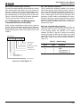
Enable/Disable. The frame status FIFO is enabled when
WR15 bit D2 is set and the CMOS/ESCC is in the
SDLC/HDLC mode. Otherwise, the status register contents bypass the FIFO and go directly to the bus interface
(the FIFO pointer logic is reset either when disabled or via
a channel or Power-On Reset). The FIFO mode is disabled on power-up (WR15 D2 is set to 0 on reset). The
effects of backward compatibility on the register set are
that RR4 is an image of RR0, RR5 is an image of RR1,
RR6 is an image of RR2 and RR7 is an image of RR3. For
the details of the added registers, refer to Chapter 5. The
status of the FIFO Enable signal can be obtained by reading RR15 bit D2. If the FIFO is enabled, the bit is set to 1;
otherwise, it is reset.
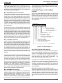
Read Operation. When WR15 bit D2 is set and the FIFO
is not empty, the next read to any of status register RR1 or
the additional registers RR7 and RR6 is from the FIFO.
Reading status register RR1 causes one location of the
FIFO to be emptied, so status is read after reading the byte
count, otherwise the count is incorrect. Before the FIFO
underflows, it is disabled. In this case, the multiplexer is
switched to allow status to read directly from the status
register, and reads from RR7 and RR6 contain bits that are
undefined. Bit D6 of RR7 (FIFO Data Available) is used to
determine if status data is coming from the FIFO or directly
from the status register, since it is set to 1 whenever the
FIFO is not empty.
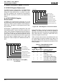
0
4
1
2
3
5
6
7
00
F A
D
D 00
D D
C
C
F
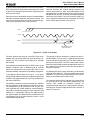
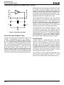
Internal Byte Strobe
Increments Counter
Don't Load
Counter On
1st Flag
Reset Byte
Counter Here
Since not all status bits are stored in the FIFO, the All
Sent, Parity, and EOF bits bypass the FIFO. The status
bits sent through the FIFO are Residue Bits (3), Overrun,
and CRC Error.
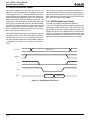
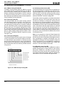
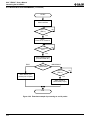
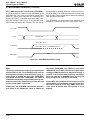
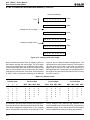
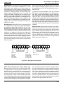
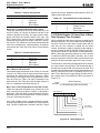
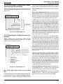
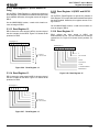
The sequence for proper operation of the byte count and
FIFO logic is to read the register in the following order:
RR7, RR6, and RR1 (reading RR6 is optional). Additional
logic prevents the FIFO from being emptied by multiple
reads from RR1. The read from RR7 latches the FIFO
empty/full status bit (D6) and steers the status multiplexer
to read from the CMOS/ESCC megacell instead of the status FIFO (since the status FIFO is empty). The read from
RR1 allows an entry to be read from the FIFO (if the FIFO
was empty, logic was added to prevent a FIFO underflow
condition).
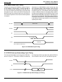
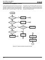
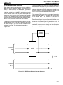
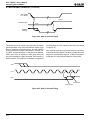
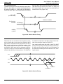
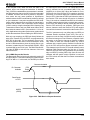
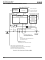
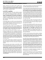
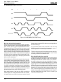
Write Operation. When the end of an SDLC frame (EOF)
has been received and the FIFO is enabled, the contents
of the status and byte-count registers are loaded into the
FIFO. The EOF signal is used to increment the FIFO. If the
FIFO overflows, the RR7 bit D7 (FIFO Overflow) is set to
indicate the overflow. This bit and the FIFO control logic is
reset by disabling and re-enabling the FIFO control bit
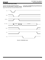
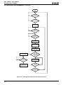
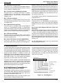
(WR15 bit 2). For details of FIFO control timing during an
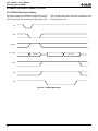
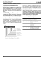
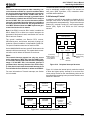
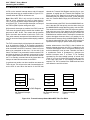
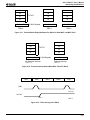
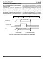
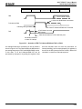
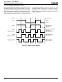
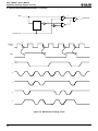
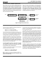
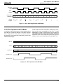
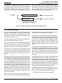
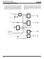
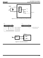
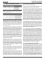
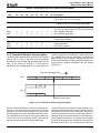
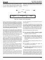
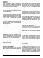
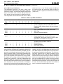
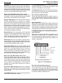
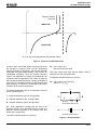
SDLC frame, refer to Figure 4-16.
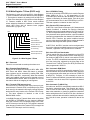
4
0
1
2
3
5
6
7
0
F
A
D
D 00
D D
C
C
F
Internal Byte Strobe
Increments Counter
Reset
Byte Counter
Load Counter
Into FIFO and
Increment PTR
Reset
Byte Counter
Reset
Byte Counter
Load Counter
Into FIFO And
Increment PTR
Figure 4-16. SDLC Byte Counting Detail
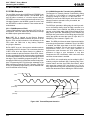
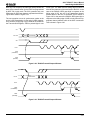
SDLC Status FIFO Anti-Lock Feature (ESCC only).
When the Frame Status FIFO is enabled and the ESCC
is programmed for Special Receive Condition Only
(WR1 D4=D3=1), the data FIFO is not locked when a
character with End of Frame status is read. When a character with the EOF status reaches the top of the FIFO,
an interrupt with a vector for receive data is generated.
The command Reset Highest IUS must be issued at the
end of the interrupt service routine regardless of whether
an interrupt acknowledge cycle had been executed (hard-
ware or software). This allows a DMA to complete a transfer of the received frame to memory and then interrupt the
CPU that a frame has been completed without locking the
FIFO. Since in the Receive Interrupt on Special Condition
Only mode the interrupt vector for receive data is not used,
it is used to indicate that the last byte of a frame has been
read from the Receive FIFO. This eliminates having to
read the frame status (CRC and other status is stored in
the status FIFO with the frame byte count).
4-29
4