1
BarrettHand
BH8-255 User Manual
July 21, 1999
version 1.0
TABLE OF CONTENTS
1 SYSTEM DESCRIPTION............................................................................................ 8
1.1 STANDARD BH8-255 SYSTEM COMPONENTS.......................................................................8
1.1.1 SYSTEM FEATURES..........................................................................................................8
1.1.2 DOCUMENTATION............................................................................................................8
1.1.3 BARRETTHAND...............................................................................................................9
1.1.4 POWER SUPPLY.............................................................................................................10
1.1.5 LAB BENCH STAND.......................................................................................................11
1.1.6 ELECTRICAL CABLES......................................................................................................11
1.1.7 CONTROL SOFTWARE AND FIRMWARE...............................................................................11
1.1.8 MAINTENANCE KIT........................................................................................................12
1.2 SYSTEM OPTIONS............................................................................................................13
1.2.1 ARM ADAPTER..............................................................................................................13
1.2.2 C-FUNCTION LIBRARY...................................................................................................13
1.2.3 STRAIN GAGE JOINT-TORQUE SENSORS.............................................................................14
1.2.4 CONTROL SOFTWARE/FIRMWARE UPGRADES.....................................................................14
2 SAFETY AND CAUTIONS....................................................................................... 15
3 SYSTEM SETUP........................................................................................................ 17
3.1 MOUNTING REQUIREMENTS.............................................................................................17
3.1.1 LAB BENCH STAND.......................................................................................................17
3.1.2 OPTIONAL ARM ADAPTER..............................................................................................17
3.2 ELECTRICAL CONNECTIONS..............................................................................................18
3.3 HOST COMPUTER............................................................................................................19
3.4 INSTALLING BH8-255 CONTROL SOFTWARE....................................................................19
3.5 DOWNLOAD FIRMWARE...................................................................................................19
4 BARRETTHAND OPERATION............................................................................... 21
4.1 POWER-UP SEQUENCE.....................................................................................................21
4.2 BARRETTHAND CONTROL................................................................................................21
4.2.1 SUPERVISORY CONTROL.................................................................................................21
4.2.2 COMMAND STRUCTURE..................................................................................................22
4.2.3 FIRMWARE PARAMETERS................................................................................................23
4.2.4 FIRMWARE COMMANDS..................................................................................................29
4.2.5 REALTIME CONTROL.....................................................................................................33
4.2.6 STATUS CODES.............................................................................................................35
4.3 EXAMPLE PROGRAMS......................................................................................................36
4.3.1 SUPERVISORY MODE EXAMPLE PROGRAM.........................................................................36
1
Barrett Technology, Inc.
BH8-255 User Manual, version 1.0
4.3.2 REALTIME MODE EXAMPLE PROGRAM............................................................................38
5 MAINTENANCE........................................................................................................ 41
5.1 FINGER CABLE PRETENSION............................................................................................41
5.2 FASTENER CHECK...........................................................................................................42
5.3 LUBRICATION..................................................................................................................43
5.4 STRAIN GAGES................................................................................................................47
6 TROUBLESHOOTING............................................................................................. 50
7 THEORY OF OPERATION...................................................................................... 58
7.1 ELECTRONIC ARCHITECTURE...........................................................................................58
7.2 MOTOR CONTROL...........................................................................................................59
7.3 MECHANISMS..................................................................................................................61
7.3.1 TORQUESWITCH™........................................................................................................61
7.3.2 SPREAD MOTION...........................................................................................................64
7.4 OPTIONAL STRAIN GAGE JOINT-TORQUE SENSOR.............................................................65
7.5 KINEMATICS...................................................................................................................66
7.6 JOINT MOTION LIMITS....................................................................................................76
2
Barrett Technology, Inc.
BH8-255 User Manual, version 1.0
LIST OF FIGURES
FIGURE 1 - BARRETTHAND....................................................................................... 9
FIGURE 2 - BARRETTHAND POWER SUPPLY..................................................... 10
FIGURE 3 - LAB BENCH STAND.............................................................................. 11
FIGURE 4 - ARM ADAPTER...................................................................................... 13
FIGURE 5 - LAB BENCH STAND WITH WIRE STRAIN RELIEF.......................17
FIGURE 6 - INSTALLING AN ARM ADAPTER...................................................... 18
FIGURE 7 - PRETENSIONING THE TENDON CABLE......................................... 41
FIGURE 8 - IMPORTANT FASTENER LOCATIONS............................................. 42
FIGURE 9 - LUBRICANT APPLICATION POINTS................................................ 44
FIGURE 10 - FINGER ATTACHMENT-SCREW LOCATION............................... 45
FIGURE 11 - REMOVING THE FINGERS FOR MAINTENANCE.......................46
FIGURE 12 - RESETTING THE FINGERTIP POSITION AFTER FINGER
REMOVAL.................................................................................................................... 46
3
Barrett Technology, Inc.
BH8-255 User Manual, version 1.0
FIGURE 13 - REATTACHING FINGERS AFTER MAINTENANCE....................47
FIGURE 14 - SHROUD REMOVAL........................................................................... 48
FIGURE 15 - BALANCING POTENTIOMETER..................................................... 48
FIGURE 16 - FACTORY-SET DIP SWITCHES........................................................ 50
FIGURE 17 - CABLE AND IDLER PULLEY............................................................ 51
FIGURE 18 - MANUAL TORQUESWITCH™ ACTIVATION............................... 54
FIGURE 19 - SHROUD COVER REMOVAL............................................................ 56
FIGURE 20 - BARRETTHAND CONTROLLER BLOCK DIAGRAM..................58
FIGURE 21 - BARRETT'S PATENTED TORQUESWITCH™ MECHANISM.....62
FIGURE 22 - TORQUESWITCH™ OPERATION.................................................... 64
FIGURE 23 - STRAIN GAGE JOINT-TORQUE SENSOR......................................65
FIGURE 24 - STRAIN GAGE TORQUE CURVES................................................... 66
FIGURE 25 - BARRETTHAND IN ZERO POSITION............................................. 69
FIGURE 26 - D-H FRAME ASSIGNMENT FOR FINGER F1................................. 70
4
Barrett Technology, Inc.
BH8-255 User Manual, version 1.0
FIGURE 27 - D-H FRAME ASSIGNMENT FOR FINGER F2................................. 72
FIGURE 28 - D-H FRAME ASSIGNMENT FOR FINGER F3................................. 74
FIGURE 29 - FINGER JOINT MOTION LIMIT RANGE....................................... 76
FIGURE 30 - SPREAD JOINT MOTION LIMIT RANGE....................................... 77
FIGURE 31 - BARRETTHAND DIMENSIONS......................................................... 79
FIGURE 32 - TORQUESWITCH ACTIVATION GRAPH....................................... 81
LIST OF TABLES
TABLE 1 - FIRMWARE FILE LIST........................................................................... 20
TABLE 2 - MOTOR PREFIXES.................................................................................. 22
TABLE 3 - REALTIME CONTROL PARAMETERS............................................... 34
TABLE 4 - HAND STATUS CODES........................................................................... 35
TABLE 5 - LUBRICATION SCHEDULE................................................................... 43
TABLE 6 - BARRETTHAND MOTOR PROPERTIES............................................. 59
5
Barrett Technology, Inc.
BH8-255 User Manual, version 1.0
TABLE 7 - D-H PARAMETER VALUES FOR ALL FINGERS.............................. 67
TABLE 8 - D-H LINK PARAMETERS FOR FINGER F1........................................ 70
TABLE 9 - D-H LINK PARAMETERS FOR FINGER F2........................................ 72
TABLE 10 - D-H LINK PARAMETERS FOR FINGER F3...................................... 74
LIST OF EQUATIONS
EQUATION 1 - VELOCITY CONVERSION............................................................. 59
EQUATION 2 - VELOCITY CONTROL.................................................................... 60
EQUATION 3 - TRAPEZOIDAL PROFILE CONTROL.........................................60
EQUATION 4 - MOTOR ACCELERATION............................................................. 61
EQUATION 5 - HOMOGENEOUS TRANSFORM BETWEEN {K-1} AND {K}...67
EQUATION 6 - FORWARD KINEMATICS FROM FINGERTIP TO WORLD...67
EQUATION 7 - MOTOR TO JOINT ANGLE TRANSFORM BEFORE
TORQUESWITCH™ ACTIVATION......................................................................... 68
EQUATION 8 - MOTOR TO JOINT ANGLE TRANSFORM AFTER
TORQUESWITCH™ ACTIVATION........................................................................ 68
6
Barrett Technology, Inc.
BH8-255 User Manual, version 1.0
EQUATION 9 - FORWARD KINEMATICS FOR FINGER F1............................... 71
EQUATION 10 - FORWARD KINEMATICS FOR FINGER F2............................. 73
EQUATION 11 - FORWARD KINEMATICS FOR FINGER F3............................. 75
7
Barrett Technology, Inc.
BH8-255 User Manual, version 1.0
1 System Description
1.1
Standard BH8-255 System Components
1.1.1
System Features
Thank you for selecting the most versatile robotic hand ever made. The
BarrettHand is designed as an affordable, practical compromise between
inflexible industrial grippers and highly dexterous, but bulky and expensive
research hands. The BarrettHand is lightweight and self-contained like a gripper,
but programmable like a dexterous research hand. The BarrettHand is a multifingered grasper with the dexterity to secure target objects of different sizes,
shapes, and orientations. Even with its low weight (1.18kg) and compact form, it
is totally self-contained. Integration with any arm is fast and simple by using
industry-standard serial communications.
The BarrettHand is ideal for mounting on almost any robot arm due to its compact
and lightweight construction. Its low mass and short base-to-graspcenter distance
minimize joint loading on the host robot and reduce extraneous arm movements
during object reorientation. The custom control-electronics package is contained
entirely within the palm shell, reducing electrical wiring to a single cable carrying
all communications and motor power.
1.1.2
Documentation
Barrett Technology provides two different manuals to assist you in learning about
the BarrettHand. The first manual is the BH8-255 User Manual and contains
information about:
•
•
•
•
•
•
•
System components and options
System setup and operation
Maintenance
Troubleshooting
Theory of operation
Technical specifications
Frequently asked questions
The second manual is the BHControl Interface Manual and is a tool for learning
the BHControl Interface. The BHControl Interface is a Windows application and
allows you to control the BarrettHand quickly and easily. Refer to this manual for
instructions on how to control the BarrettHand.
Both manuals are also in electronic form on the Control Software diskettes.
8
Barrett Technology, Inc.
BH8-255 User Manual, version 1.0
1.1.3
BarrettHand
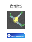
The BarrettHand, shown in Figure 1, is comprised of three fingers, two of which
rotate about the base joint. The fingers are labeled F1, F2 and F3. Each of the
three fingers on the BarrettHand feature two joints driven by a single DC
brushless servo motor. Finger joints are coupled through Barrett’s patented
TorqueSwitch™, which automatically switches motor torque to the appropriate
finger joint when closing on a target object. Using the fingers together allows the
BarrettHand to "grasp" different objects securely.
The fourth motor moves F1 and F2 in the coupled “spread” motion around the
palm, allowing “on-the-fly” grasp reconfiguration to adapt to varying target object
sizes, shapes, and orientations. The BarrettHand spread function, in conjunction
with the TorqueSwitch™, effectively makes object-grasping target-independent.
The BarrettHand, shown in Figure 1, is equipped with a threaded base for easy
mounting. The threaded base is fully compatible with the BarrettArm and, with
the optional arm adapter, can be mounted on virtually any robot. This allows for
easy installation and maintenance of the BarrettHand.
F2
F1
F1 and F2 Spread
around the Palm
Threaded
Ring for
Quick
Connection
TorqueSwitch™
Shifts Torque to
Appropriate Finger
Joint
Onboard Control
Electronics Package in
Palm Shell
F3
Figure 1 - BarrettHand
9
Barrett Technology, Inc.
BH8-255 User Manual, version 1.0
1.1.4
Power Supply
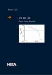
The Power Supply, shown in Figure 2, provides all DC motor bus voltage,
electronic component logic voltage and passes RS-232 commands from the host
computer to the control electronics in the BarrettHand palm shell. This Power
Supply auto-switches for international voltage standards and contains built-in
surge protection, shielding an attached BarrettHand from surges in the AC linevoltage.
The three connections to the Power Supply are the AC line voltage, RS-232
connection from the host computer and a connection for carrying signal and
power to and from the BarrettHand. The Power Supply is also equipped with a
button to reset the BarrettHand and two LED's indicating the presence of proper
voltage levels. The red LED, when illuminated, indicates valid 36 V motor
power. The green LED, when illuminated, indicates valid 5 V logic power. Refer
to Figure 2 for a detailed picture of the Power Supply.
5
1
2
6
7
4
3
1.
2.
3.
4.
5.
6.
7.
Red LED - 36 V monitor
Green LED - 5 V monitor
AC line cord connector
Power Switch
Reset Switch
15 pin female BarrettHand Cable connector
9 pin female Serial Cable connector
Figure 2 - BarrettHand Power Supply
10
Barrett Technology, Inc.
BH8-255 User Manual, version 1.0
1.1.5
Lab Bench Stand
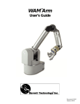
The bench mount stand for the BarrettHand, shown in Figure 3, is ideal for use in
a laboratory environment. The durable Lexan® stand comes complete with cable
management clips and mounting feature to hold your BarrettHand unit securely
on any flat surface. Non-slip rubber feet keep the stand from sliding during
testing and programming.
Figure 3 - Lab Bench Stand
1.1.6
Electrical Cables
All necessary electrical cables are included in the basic BH8-255 System. An AC
line cord connects the Power Supply to a wall source, 120/240 ±10% VAC. A
serial cable connects the Power Supply and the host computer to establish the RS232 communication link. The BarrettHand Cable connects the Power Supply to
the BarrettHand, supplying communications, logic power, and motor power. This
cable is extremely flexible allowing the BarrettHand to be used on any robot with
minimal effect on robot performance. Use the included set of twelve adhesive
guide clips for cable management. Since the control hardware resides inside the
BarrettHand itself, no other electrical cabling is required.
1.1.7
Control Software and Firmware
The BH8-255 System control software consists of the BHControl Interface
Application and Manual, BH8-255 User Manual, latest firmware version and
example programs. The BHControl Interface is a Windows application that
allows you to control the BarrettHand quickly and easily. The BHControl
Interface can be used to test Supervisory and RealTime control sequences,
measure communication loop rates, demonstrate functionality, learn how to write
11
Barrett Technology, Inc.
BH8-255 User Manual, version 1.0
and automatically generate C code independently, based on tested algorithms.
See Section 4.2 for more information on Supervisory and RealTime control and
the BHControl Interface Manual for more information on the BHControl
Interface.
The BarrettHand has firmware that resides on the control electronics. The
firmware requires only ASCII characters sent over a standard serial port. You
build the character strings to create the desired commands. The firmware then
interprets the commands sent and controls the motors, sets and retrieves
parameters, or reads and writes to the EEPROM. See Section 4.2 for more
information on firmware commands and parameters.
1.1.8
Maintenance Kit
Included in each BarrettHand package is a maintenance kit. Use the maintenance
kit in accordance with the instructions in Section 5. The maintenance kit includes
the following:
•
•
•
•
•
•
•
•
12
1.0-mm Hex wrench
1.27-mm Hex wrench
2.0-mm Hex wrench
2.5-mm Hex wrench
Mobil 1® Lubricant in syringe
Lubricant applicators
Torque wrench
2.0-mm Hex adapter for Torque wrench
Barrett Technology, Inc.
BH8-255 User Manual, version 1.0
1.2
1.2.1
System Options
Arm adapter
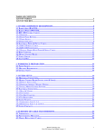
Barrett Technology can provide an arm adapter for any make or model robot.
This lightweight arm adapter is made to work with the end-effector bolt pattern on
your robot, allowing quick, easy mounting and wire management for a BH8-255
System. The arm adapter is bolted to the end of the robot arm and the
BarrettHand is secured to the arm adapter with its standard threaded locking ring,
see Figure 4. The arm adapter is also equipped with an anti-rotation feature to
prevent rotation during operation.
Arm Adapter
Figure 4 - Arm adapter
1.2.2
C-Function Library
The BarrettHand C-Function Library is a helpful tool for programming the
BarrettHand using the C language on IBM-compatible PC’s without having to
manage serial communication and timing issues. The library contains easy-to-use
functions that permit the use of Supervisory and RealTime commands in software
routines developed by the end user. All of the functions are available when the
library is linked to the program. The C-Function Library also includes a manual
that describes all of the functions in detail and gives examples.
13
Barrett Technology, Inc.
BH8-255 User Manual, version 1.0
one object and use it for all communications.. The library uses a sophisticated
multithreaded mechanism for accessing the serial port, which allows both
synchronous and asynchronous access to the low-level thread and ensures that all
serial communications are executed with high priority. The low-level thread
manages all input and output buffers and makes controlling the BarrettHand easy.
1.2.3
Strain gage Joint-Torque Sensors
Barrett Technology offers a factory-installed torque sensor for the BH8-255
System. This option uses strain gages to measures the differential tension in the
“tendon” running through each finger to the second joint. The information is
processed in additional onboard circuitry and can be accessed by requesting the
present strain gage parameter. The strain gage parameter represents the amount
strain on the strain gage sensors. The strain gage values need to be calibrated by
the customer to relate strain to joint torque. The joint torque for the second finger
joint is over a 1.0 N-m range (approximately 0.1 N-m resolution). See Section 7.4
for more detailed information on how the sensor works.
1.2.4
Control Software/Firmware Upgrades
Barrett Technology makes software and firmware upgrades periodically.
Upgrades are available for purchase or free of charge for customers of Barrett's
subscription service. Refer to Barrett's enclosed Warranty and Subscription
Service Policy for more information.
14
Barrett Technology, Inc.
BH8-255 User Manual, version 1.0
2 Safety and Cautions
PLEASE READ THIS SECTION IN ITS ENTIRETY BEFORE USING YOUR
BARRETTHAND.
Following these safety instructions will help prevent user injury and equipment
damage.
15
•
As with any piece of robotic equipment, it is ultimately up to you to be aware
of your surroundings during robot operation. The workspace of the
BarrettHand (whether attached to a robot arm or its lab bench stand) should be
clearly marked to prevent persons or objects from inadvertently entering the
equipment’s reach. Before attaching the BarrettHand, test host robot
trajectories to confirm that it will not inadvertently collide with other objects
in the workspace.
•
NEVER connect or disconnect any electrical cables while the Power Supply is
turned on. Failure to follow this instruction could impart irreparable damage
to the onboard electronics or put you at risk of electrical shock.
•
Always plug the Power Supply into a properly grounded wall source. Failure
to do so could damage the BarrettHand electronics and put you at risk of
electrical shock.
•
Do not place any part of your body or delicate objects within the grasp of the
BarrettHand without first verifying control of the unit and confirming
appropriate force levels.
•
Do not allow the BarrettHand to be exposed to liquids that may cause
electrical short-circuits and put you at the risk of electrical shock.
•
Keep dirt away from the exposed gear and cable drives located at the joints.
•
Do not exceed the load limit of the fingers, 2 kg per finger at any point along
the outer link. Consider all loading situations including accelerated loads,
cantilever loads from long objects, robot collisions, active loads, etc.
•
A portion of the onboard control electronics is exposed through the base of the
BarrettHand. Before installing to a robot arm, take necessary precautions to
protect the electronics from impact, contaminants and static discharge. Do not
rest the BarrettHand unit directly on its base. Use the included lab bench
stand during standalone operation.
•
Remove the fingers only as instructed in Section 5.3.
Barrett Technology, Inc.
BH8-255 User Manual, version 1.0
•
Monitor the operating temperature of the BarrettHand so that it does not
exceed 65° C. The BarrettHand was designed with non-backdrivable finger
joints to take advantage of the motors peak operating performance in short
bursts. The spread, however, is backdrivable to aid in target-independent
grasping (see Section 7.3.2) and requires constant motor current to actively
hold position. Idling the spread motor, when possible, will help keep the
temperature lower.
16
Barrett Technology, Inc.
BH8-255 User Manual, version 1.0
3 System Setup
3.1
3.1.1
Mounting Requirements
Lab Bench Stand
When writing custom programs for the BarrettHand or using the unit without a
host robot arm, Barrett Technology recommends using the lab bench stand
included and all its wire management clips as shown in Figure 5. These clips
prevent the cable from pulling out of the BarrettHand while the Power Supply is
turned on. Under no circumstances should the BarrettHand be operated while
resting unsecured on a tabletop or any other surface.
Figure 5 - Lab Bench Stand with Wire Strain Relief
To secure the BarrettHand to the lab bench stand, flip the stand upside down.
Pass the base ring of the BarrettHand up through the center hole of the stand and
retain it with the threaded locking ring provided with your system, see Figure 5.
Note the alignment of the BarrettHand, relative to the wire strain relief clips, to
ease connection of the BarrettHand Cable.
Make sure the Power Supply is turned OFF, route the BarrettHand Cable through
all three cable clips on the lab bench stand and plug it into the BarrettHand.
Tighten the cable clips to hold the cable in place.
3.1.2
Optional Arm Adapter
Like the lab bench stand, the arm adapter is made to retain the BarrettHand in
place and to handle wiring from the hand, see Figure 6. The arm adapter,
however, can be designed for mounting on your specific robot arm.
To mount your BarrettHand on a robot, bolt the arm adapter onto the end-effector
bolt circle. Insert the threaded base of the BarrettHand through the hole in the
arm adapter shown in Figure 6 paying attention to the indexing tabs in the arm
adapter. These tabs fit into the mating slots on the base of the BarrettHand.
17
Barrett Technology, Inc.
BH8-255 User Manual, version 1.0
Secure the BarrettHand by threading the locking ring (included with your system)
onto the base of the BarrettHand
The BarrettHand Cable is extremely flexible and should be routed close to the
center of each revolute joint and along the axis of travel for prismatic joints.
Mount the cable clips to a flat, dry and clean surface. Clean cable clip attachment
areas with alcohol before attaching. Verify the Power Supply is turned OFF, then
route the BarrettHand Cable through the cable retaining clips on the robot and the
arm adapter and plug into the BarrettHand and the Power Supply. Tighten the
cable clips to hold the cable in place.
Figure 6 - Installing an Arm Adapter
3.2 Electrical Connections
After mounting the BarrettHand according to Section 3.1, you should connect the
electrical cables required for operation.
Check the Power Supply to confirm that it is turned OFF.
• Verify the Power Supply is on a flat, stable surface.
• Plug the free end of the BarrettHand Cable into the female 15 pin D-sub
connector on the back of the Power Supply.
• Plug the serial cable into the computer’s serial port (usually COM1).
18
Barrett Technology, Inc.
BH8-255 User Manual, version 1.0
•
•
•
Plug the other end of the serial cable into the female 9 pin D-sub connector on
the back of the Power Supply. Barrett Technology supplies a standard 3meter straight through serial cable, but you may purchase a longer cable if
desired.
Connect the AC line cord to the socket on the back panel.
Plug the other end of the AC line cord into a suitable AC wall source.
3.3 Host Computer
The BH8-255 Control Software was written for computers running Windows
95/98/NT 4.0. Barrett Technology recommends using a Pentium based processor
with a minimum CPU clock speed of 266 MHz and 32 Mbytes of RAM. The
software requires 10 Mbytes of free disk space.
3.4
Installing BH8-255 Control Software
The BH8-255 Control Software consists of the BHControl Interface, firmware
and example programs. The BHControl Interface is a Windows API that allows
you to control the BarrettHand quickly and easily. The BHControl Interface can
be used to test Supervisory and RealTime control sequences, communication loop
rates, demonstrate functionality, learn how to independently write C code and
automatically generate C code based on tested algorithms1. Run the setup.exe
program on the disk labeled BH8-255 Control Software Disk 1 of 5. This will
install all necessary files for using the BHControl Interface, the most recent
version of firmware, online manuals and example programs.
3.5 Download Firmware
The BarrettHand has firmware that resides in the onboard electronics. This
firmware is stored in RAM that receives its power from the Power Supply when
the system is turned on and from an embedded super capacitor when powered
down. This super capacitor maintains the firmware in RAM from one day up to
one week, before the capacitor is fully discharged and the memory is cleared.
When the firmware has been cleared, it will need to be reinstalled. The download
process takes only a few minutes, as follows:
1.
2.
3.
4.
5.
6.
7.
1
19
Verify BarrettHand is plugged into the Power Supply.
Verify the host computer is plugged into the Power Supply.
Verify the Power Supply is attached to a power source and turned on.
Run the BHControl Interface program BHControl.exe.
Initialize the software by pressing the Initialize Library button.
Press the Start Download button.
Open the appropriate file according to Table 1.
The code generated by the Control Interface requires the C-Function Library to compile.
Barrett Technology, Inc.
BH8-255 User Manual, version 1.0
8. Press Reset on the Power Supply.
9. After downloading the file, the BarrettHand is ready for operation.
Table 1 - Firmware File List
File Name
BarrettHand Firmware v3_0.S19
Description
Version 3.0 Firmware
BarrettHand Firmware v4_02.S19
Version 4.02 Firmware with RealTime
mode capabilities.
20
Barrett Technology, Inc.
BH8-255 User Manual, version 1.0
4 BarrettHand Operation
4.1 Power-Up Sequence
Once the steps in Section 3 are complete, your BH8-255 System is ready for use.
Power up the system according to the instructions below.
1. Turn on the host computer.
2. Verify the serial cable is plugged into the desired communications port and
into the 9-pin connector on the back of the Power Supply.
3. Verify the BarrettHand Cable is plugged into the 15-pin connector on the back
of the Power Supply and into the bottom of the BarrettHand.
4. Verify the AC line cord is plugged into a valid power source (see 7.6) and into
the power outlet on the back of the Power Supply.
5. Turn on the Power Supply. The main power switch is located on the back
panel.
6. The BarrettHand is now ready for operation.
4.2 BarrettHand Control
This section will explain the command structure to communicate with the
BarrettHand. The BarrettHand C-Function Library incorporates functions that
build and send these commands for you. However, if you choose not to use the
C-Function Library, the BarrettHand expects commands in the following format.
4.2.1
Supervisory Control
The BarrettHand can be used in either a high-level Supervisory mode or a lowlevel RealTime mode. Supervisory mode allows you to command individual or
multiple motors to close, open and move to specific positions. You also have
access to all of the parameters, which are listed in Section 4.2.3. This set of
commands is commonly used for most grasping situations. If real-time control of
the motor position, velocity or strain is needed, use the RealTime control
described in Section 4.2.5.
Supervisory mode accepts commands from the user program and will not return
control of the BarrettHand until the command is finished being processed. The
BarrettHand expects valid commands and will return a status code for an invalid
command or if another problem occurs. See Section 4.2.6 for more detailed
information on status codes. When the command is finished being executed, all
status codes and requested information have been sent, the hand will return the
command prompt "=>". At this point, you can send another command.
21
Barrett Technology, Inc.
BH8-255 User Manual, version 1.0
4.2.2
Command Structure
Firmware resides on the BarrettHand and interprets the commands it receives.
This command structure allows you to build the desired command easily. The
format is as follows:
<Motor><Command> <Parameter> <Value>
Following is a list of the <Motor> prefixes:
Table 2 - Motor Prefixes
Value
1
2
3
4
G
S
<No Motor Specified>
Motor
Finger F1
Finger F2
Finger F3
Spread
Finger F1, Finger F2, Finger F3
Spread
Finger F1, Finger F2, Finger F3,
Spread (see the Firmware Parameter
EN in Section 4.2.3)
Note: Any combination of motor prefixes can be used together to produce the
desired result. Example: 12<Command> <Parameter> <Value> will activate
Fingers F1 and F2.
See Sections 4.2.3 and 4.2.4 for parameter value and command information.
22
Barrett Technology, Inc.
BH8-255 User Manual, version 1.0
4.2.3
Firmware Parameters
Parameter:
Purpose:
Values:
Default:
Notes:
ACCEL
Acceleration value for position control.
0 - 32767
Grasp:
1
Spread:
1
See Section 7.2 for more detailed description of how ACCEL
affects motion.
Parameter:
Purpose:
Values:
Default:
Notes:
BAUD
Returns the current baud rate of the hand divided by 100.
6, 12, 24, 48, 96, 192 and 384
96
The value returned is in hundreds of bytes per second. To
determine the actual baud rate, multiply the value returned by 100.
Parameter:
Purpose:
Values:
Default:
Notes:
DP
This parameter defines the default position for a move command.
0 - 20000 encoder counts
150 (Spread), 1000 (Fingers)
None.
Parameter:
Purpose:
DS
This parameter defines default step sizes for incremental open and
close commands.
0 - 20000 encoder counts
150 (Spread), 1200 (Fingers)
None.
Values:
Default:
Notes:
Parameter:
Purpose:
Values:
Default:
Notes:
EN
Specifies if a motor should be selected when a command has no
prefix.
TRUE (selected), FALSE (not selected)
Grasp:
TRUE
Spread:
TRUE
When a close command is issued, C, with no motor prefixes, all
motors will close with the default values.
Barrett Technology, Inc.
BH8-255 User Manual, version 1.0
23
Parameter:
Purpose:
Values:
Default:
Notes:
Parameter:
Purpose:
Values:
Default:
Notes:
FDZ
Derivative zero value for the motor control filter.
0 - 255
Grasp:
221
Spread:
221
See section 7.2 for more detailed description of how FDZ affects
motion.
FIP
Integral pole value for the motor control filter.
0 - 255
Grasp:
66
Spread:
66
See section 7.2 for more detailed description of how FIP affects
motion.
Parameter:
Purpose:
Values:
Default:
FPG
Proportional gain value for the motor control filter.
0 - 255
Grasp: 200
Spread: 100
Notes: See Section 7.2 for more detailed description of how FPG affects motion.
Parameter:
Purpose:
Values:
Default:
Notes:
Parameter:
Purpose:
Values:
Default:
Notes:
HOLD
Specifies if a motor should hold position when idled.
TRUE (hold position), FALSE (do not hold position)
Grasp:
FALSE
Spread:
TRUE
Because the fingers are not backdrivable when the motors are idled
they will not be able to move freely. However, because the spread
is backdrivable it requires this parameter be TRUE to hold its
position when idled.
LCPG
This flag specifies if the RealTime control block contains control
proportional gain.
FALSE (does not contain), TRUE (does contain)
FALSE
Motor command = (LCPG / 4) * (Control Velocity - Actual
Velocity)
Barrett Technology, Inc.
BH8-255 User Manual, version 1.0
24
Parameter:
Purpose:
Values:
Default:
Notes:
Parameter:
Purpose:
Values:
Default:
Notes:
LCV
This flag specifies if the RealTime control block contains control
velocity.
FALSE (does not contain), TRUE (does contain)
TRUE
The size of the control velocity should be 1 signed byte.
LCVC
LCV is multiplied by the control velocity coefficient (LCVC) to
determine the control velocity.
0 - 255
1
Control velocity = LCV * LCVC
Parameter:
Purpose:
LFAP
This specifies if the RealTime feedback block contains the
feedback absolute position.
Values:
FALSE (does not contain), TRUE (does contain)
Default:
TRUE
Notes: The size of the feedback absolute position should be an unsigned 2-byte
word.
Parameter:
Purpose:
LFDP
This flag specifies if the RealTime feedback block contains the
feedback delta position.
Values:
FALSE (does not contain), TRUE (does contain)
Default:
FALSE
Notes: The size of the feedback delta position should be 1 signed byte.
Parameter:
Purpose:
LFDPC
The actual change in position is divided by feedback delta position
coefficient (LFDPC) to determine LFDP.
Values:
0 - 255
Default:
1
Notes: Delta position is the change in position from the last reported position and
is limited to one signed byte. The current position is read and
compared to the last reported position. The difference is divided
by the RealTime variable LFDPC, clipped to a single signed byte,
and then sent to the host. The value sent to the host should be
multiplied by LFDPC and then added to the last reported position.
Barrett Technology, Inc.
BH8-255 User Manual, version 1.0
25
Parameter:
Purpose:
LFS
This specifies if the RealTime feedback block contains the
feedback strain gage value.
Values:
FALSE (does not contain), TRUE (does contain)
Default:
TRUE
Notes: The size of the feedback strain gage value should be 1 unsigned byte.
Parameter:
Purpose:
Values:
Default:
Notes:
LFV
This specifies if the RealTime feedback block contains feedback
velocity.
FALSE (does not contain), TRUE (does contain)
TRUE
The size of the feedback velocity should be 1 signed byte. The
actual velocity is LFC*LFVC.
Parameter:
Purpose:
LFVC
Actual velocity is divided by feedback velocity coefficient (LFVC)
to determine LFV.
Values:
0 - 255
Default:
1
Notes: On the host computer the actual velocity of the motors is equal to LFV *
LFVC.
Parameter:
Purpose:
Values:
Default:
Notes:
MCV
This parameter defines the maximum close velocity.
0 - 255
35 (Spread), 65 (Fingers)
See Section 7.2 for more information on velocity.
Parameter:
Purpose:
Values:
Default:
Notes:
MOV
This parameter defines the maximum open velocity.
0 - 255
35 (Spread), 55 (Fingers)
The minimum velocity required to reset the TorqueSwitch™ and
open and close the fingers is 40. See Section 7.2 for more
information on velocity.
Barrett Technology, Inc.
BH8-255 User Manual, version 1.0
26
Parameter:
Purpose:
Values:
Default:
Notes:
Parameter:
Purpose:
Values:
Default:
Notes:
Parameter:
Purpose:
Values:
Default:
Notes:
MPE
Maximum position error allowed for a commanded position.
0 - 30,000
Grasp:
25
Spread:
25
If the final position is not within +/- MPE encoder counts of the
desired position then the hand will return an error.
MSG
This parameter defines the maximum strain gage value before the
motor is stopped.
0 - 256
256
Setting the value to 256 indicates that the strain gage value will
never stop the motors.
P
This parameter specifies the present motor position.
0 - 20000 encoder counts
N/A
This parameter can not be set.
This section lists all of the firmware parameters and their values for BarrettHand.
Parameter: S
Purpose:
This parameter defines the current state of the motor.
Values:
0 (motor found and initialized) or 1 (motor not initialized)
Default:
N/A
Notes:
This parameter can not be set.
Parameter:
Purpose:
Values:
Default:
Notes:
SG
This parameter specifies the current strain gage value.
0 - 255
N/A
This parameter can not be set.
Barrett Technology, Inc.
BH8-255 User Manual, version 1.0
27
Parameter:
Purpose:
Values:
Default:
Notes:
Parameter:
Purpose:
Values:
Default:
Notes:
Parameter:
Purpose:
Values:
Default:
Notes:
SGFLIP
Specifies if the reported strain should be (255 - actual strain).
TRUE (reported strain = (255 - actual strain)), FALSE (reported
strain = actual strain)
Grasp:
FALSE
Spread:
N/A
Setting this value will inverse the direction of the change in strain
for a given torque.
TEMP
Returns the present temperature on the CPU board in tenths of
degrees Celsius.
-550 to 1250
N/A
The value returned is in tenths of degrees. To determine the actual
temperature, divide the value by 10.
TSTOP
Time in milliseconds before the motor is considered stopped.
0 - 32767
Grasp:
30
Spread:
30
None.
Barrett Technology, Inc.
BH8-255 User Manual, version 1.0
28
4.2.4
Firmware Commands
Command:
Function:
Parameters:
Notes:
C
Closes specified motors.
N/A
None.
Command:
Function:
Parameters:
Notes:
ERR
Returns a description of the status code specified.
Status code numbers.
Does not take motor prefixes. See Section 4.2.6 for more
information on status codes.
Command:
Function:
FDEF
Loads the factory default values of the parameters from EEPROM
into memory.
N/A
This command loads the following parameters: MCV, MOV, DS,
MSG, DP, FPG, FIP, FDZ, EN, SGFLIP, ACCEL, MPG, TSTOP,
HOLD, LCV, LCVC, LCPG, LFV, LFVC, LFS, LFAP, LFAP,
LFDPC.
See Section 4.2.3 for the default parameter values.
Parameters:
Notes:
Command:
Function:
Parameters:
29
Notes:
FGET
Gets the specified parameters.
MOV, MCV, MSG, DS, DP, LCV, LCVC, LCPG, LFV, LFVC,
LFS, LFAP, LFDP, LFDPC, FPG, FIP, FDZ, ACCEL, MPE,
TSTOP, HOLD, SGFLIP, EN, BAUD, S, P, SG
See Section 4.2.3 for more information on firmware parameters.
Command:
Function:
Parameters:
Notes:
FLISTA
Lists all of parameters and their read/write status.
N/A
Does not take motor prefixes.
Command:
Function:
Parameters:
Notes:
FLISTAV
Lists all of the present parameter values.
N/A
The parameters are listed in the same order they are displayed by
the command FLISTA. This command does not take motor
prefixes.
Barrett Technology, Inc.
BH8-255 User Manual, version 1.0
Command:
Function:
Parameters:
Notes:
FLOAD
Loads the saved parameters from EEPROM into memory.
N/A
This command loads the following parameters: MCV, MOV, DS,
MSG, DP, FPG, FIP, FDZ, EN, SGFLIP, ACCEL, MPG, TSTOP,
HOLD, LCV, LCVC, LCPG, LFV, LFVC, LFS, LFAP, LFAP,
LFDPC.
See Section 4.2.3 for the parameter definitions.
Command:
Function:
Parameters:
Notes:
FSAVE
Saves the present values of the parameters to EEPROM.
N/A
This command saves the following parameters: MCV, MOV, DS,
MSG, DP, FPG, FIP, FDZ, EN, SGFLIP, ACCEL, MPG, TSTOP,
HOLD, LCV, LCVC, LCPG, LFV, LFVC, LFS, LFAP, LFAP,
LFDPC.
See Section 4.2.3 for the parameter definitions.
Command:
Function:
Parameters:
FSET
Sets the specified parameters to the desired value.
MOV, MCV, MSG, DS, DP, LCV, LCVC, LCPG, LFV, LFVC,
LFS, LFAP, LFDP, LFDPC, FPG, FIP, FDZ, ACCEL, MPE,
TSTOP, HOLD, SGFLIP, EN, BAUD
See Section 4.2.3 for information on the firmware parameters.
Notes:
Command:
Function:
Parameters:
Notes:
Command:
Function:
Parameters:
Notes:
30
HI
Initializes the finger and spread motors. Opens all of the joints to
their full open position and sets it to be zero.
N/A
The BarrettHand will vibrate the joints during this operation. This
command needs to be executed before any motion commands.
IC
Incremental close for specified motors.
N/A
The increment size is defined in the parameter DS.
Barrett Technology, Inc.
BH8-255 User Manual, version 1.0
Command:
Function:
Parameters:
Notes:
IO
Incremental open of specified motors.
N/A
The increment size is defined in the parameter DS.
Command:
Function:
Parameters:
Notes:
LOOP
Enters RealTime mode for the specified motors
N/A
See Section 4.2.5 for more information on how the RealTime mode
functions.
Command:
Function:
Parameters:
Notes:
M
Move the specified motors to specified position
Motor position, 0 - 20000
If no position is given it will move to the value stored in DP.
Command:
Function:
Parameters:
Notes:
O
Opens specified motors.
N/A
None.
Command:
Function:
Parameters:
Notes:
PGET
Gets the parameter specified.
TMP
Does not take motor prefixes.
Command:
Function:
RESET
Resets the BarrettHand and loads all of the saved parameters from
EEPROM.
N/A
Does not take motor prefixes. The motors need to be reinitialized
before commanding motion after using this command. See the
command FSAVE for parameter information.
Parameters:
Notes:
Command:
Function:
Parameters:
Notes:
31
T
Stops actuating the motors.
N/A
None.
Barrett Technology, Inc.
BH8-255 User Manual, version 1.0
Command:
Function:
Parameters:
Notes:
VERS
Greeting message, shows the version number and the company
contact information.
N/A
None.
Command:
Function:
Parameters:
Notes:
?<Command>
Help information about the <Command> specified.
N/A
None.
Command:
Function:
^C
Stops the motors and clears the input buffer. A new prompt will be
output.
N/A
None.
Parameters:
Notes:
32
Barrett Technology, Inc.
BH8-255 User Manual, version 1.0
4.2.5
RealTime Control
One features of the BarrettHand is the RealTime control. This control mode
allows you to send commands and receive feedback continuously from the
BarrettHand. Any desired control law can be applied by using the host computer
to determine the desired motor command and then applying that command to the
BarrettHand in real-time. The communication bandwidth is dependent on the
amount of control information sent, feedback information requested and the
selected baud rate.
Data from the host computer to the hand is grouped into control and feedback
blocks. Each block has a single byte header, followed by a set of data. The
control block header specifies whether or not control data is to follow, and
whether or not a feedback block is to be returned. The feedback block header
returned acknowledges the receipt of the control block or indicates an error. The
control block header can also terminate the loop mode.
The possible control block header bytes are:
"C": Control data follows; respond with a feedback block
"c": Control data follows; respond with an acknowledgement character ("*")
"A": No control data follows; respond with a feedback block
"a": No control data follows; respond with an acknowledgement character
"^C": Terminate loop mode
The possible feedback block header bytes are:
"*":
The BarrettHand has received the control block successfully.
"<CRLF>ERR": An error occurred, the status code will follow immediately.
Before sending information to the BarrettHand in RealTime mode, it is necessary
to determine what the control and feedback blocks will contain. Do this by
setting the RealTime control flags before entering RealTime mode. Setting a flag
TRUE indicates that it will be part of the control or feedback block. A flag for
each motor needs to be set. Set the flags by using the FSET command. See Table
3 for a detailed description of the flags.
There are also three RealTime variables that need to be set before entering
RealTime mode. These three variables affect how the RealTime control values
are interpreted. Set these variables by using the FSET command. See Table 3 for
a detailed description of the variables.
Barrett Technology, Inc.
BH8-255 User Manual, version 1.0
33
Table 3 - RealTime Control Parameters
Parameter
LCV
Name
Loop Control
Velocity
Type
Flag
LCVC
Loop Control
Velocity
Coefficient
Loop Control
Proportional Gain
Variable
(integer)
LFV
Loop Feedback
Velocity
Flag
LFVC
Loop Feedback
Velocity
Coefficient
Loop Feedback
Strain
Variable
(integer)
LFAP
Loop Feedback
Absolute Position
Flag
LFDP
Loop Feedback
Delta Position
Flag
LFDPC
Loop Feedback
Delta Position
Coefficient
Variable
(integer)
LCPG
LFS
Flag
Flag
Function
If True, RealTime control
block will contain control
velocity
LCV is multiplied by
LCVC to determine control
velocity
If True, RealTime control
block will contain
Proportional Gain
If True, RealTime
feedback block will contain
feedback velocity
Actual velocity is divided
by LFVC to get LFV
Size in Block
1 signed byte
If True, RealTime
feedback block will contain
strain information
If True, RealTime
feedback block will contain
absolute position
If True, RealTime
feedback block will contain
delta position
The actual delta position is
divided by this to get
LFDP
1 unsigned
byte
N/A
1 unsigned
byte
1 signed byte
N/A
2 unsigned
bytes
1 signed byte
N/A
Now that all of the flags and variables have been set, it is time to begin RealTime
control. Send the command <Motors>LOOP to enter RealTime mode. At this
point the BarrettHand will respond with a "*" to acknowledge the start of
RealTime control. It is now up to the host computer to build control blocks and
send them to the BarrettHand.
Example:
This application uses fingers F1 and F2, and the spread. The fingers will receive
velocity control information and report strain and delta position. The spread will
just report delta position. All relevant coefficients will be set to 1.
Set the RealTime flags and variables by using the following commands:
12FSET LCV 1 LCVC 1 LCPG 0 LFV 0 LFS 1 LFAP 0 LFDP 1 LFDPC 1
4FSET LCV 0 LCVC 1 LCPG 0 LFV 0 LFS 0 LFAP 0 LFDP 1 LFDPC 1
Enter RealTime control by issuing the following command.
Barrett Technology, Inc.
BH8-255 User Manual, version 1.0
34
124LOOP
The BarrettHand will then send a single "*" and wait for control blocks. Each
control block will consist of three bytes:
"C" [Control data follows; respond with feedback block]
1 signed byte of velocity for motor F1
1 signed byte of velocity for motor F2
Each feedback block will consist of six bytes:
"*" acknowledge character
1 unsigned byte of strain for motor F1
1 signed byte of delta position for motor F1
1 unsigned byte of strain for motor F2
1 signed byte of delta position for motor F2
1 signed byte of delta position for motor 4
Each control block from the host will stimulate a feedback block from the
BarrettHand. When the host is finished, it will send the single character ^C
(0x03); the BarrettHand will respond by printing the command prompt "=>", and
waiting for a new command.
4.2.6
Status Codes
Status codes, see Table 4, are sent by the BarrettHand when the communication
was successful, but the BarrettHand encountered a problem. Keep in mind that
BarrettHand status codes are powers of 2, so the return value may encode multiple
flags. Example: a status code of 3, indicates status code 2 and status code 1.
Table 4 - Hand Status Codes
Hand Status Code
1
2
4
8
16
32
64
128
256
512
1024
2048
4096
Description
No motor board found
No motor found
Motor not initialized
not used
Couldn't reach position
Unknown command
Unknown parameter name
Invalid value
Tried to write a read only parameter
Timeout
Too many arguments for this command
Invalid RealTime control block header
Command can't have motor prefix
Barrett Technology, Inc.
BH8-255 User Manual, version 1.0
35
4.3
Example Programs
4.3.1
Supervisory Mode Example Program
The following program is an example that shows how to program the BarrettHand
in Supervisory mode using the C-Function Library. The code was generated
using the BHControl Interface and compiled using Microsoft Visual C++ v6.0.
This program initializes the BarrettHand and then opens and closes the grasp.
///////////////////////////////////////////////////////////
//
//
//
Automatically Generated C++ Code
//
//
BHand Control Center Version 1.0
//
//
//
//
Supervisory Mode
//
//
//
///////////////////////////////////////////////////////////
#include
#include
#include
#include
#include
BHand
int
int
<stdio.h>
<stdlib.h>
<math.h>
<conio.h>
"BHand.h"
bh;
value;
result;
// Handles all hand communication
// Hand parameter obtained with Get command
// Return value (error) of all BHand calls
///////////////////////////////////////////////////////////
// Error Handler - called whenever result!=0
void Error(void)
{
printf( "ERROR: %d\n%s\n",result,bh.ErrorMessage(result));
exit(0);
}
///////////////////////////////////////////////////////////
// Initialize hand, set timeouts and baud rate
void Initialize(void)
{
if(result=bh.InitSoftware(1,THREAD_PRIORITY_TIME_CRITICAL))
Error();
if( result=bh.ComSetTimeouts(0,100,15000,100,5000) )
Error();
if( result=bh.Baud(9600) )
Error();
if( result=bh.InitHand("") )
Error();
}
///////////////////////////////////////////////////////////
// Execute commands, return 1 if interrupted with a key
Barrett Technology, Inc.
BH8-255 User Manual, version 1.0
36
int Execute(void)
{
printf( "Press Any Key to Abort..." );
// Initializes all motors
if( result=bh.InitHand( "123S" ) )
Error();
if( _kbhit() )
{ _getch(); return 1; }
// Closes fingers F1, F2 and F3
if( result=bh.Close( "123" ) )
Error();
if( _kbhit() )
{ _getch(); return 1; }
// Opens fingers F1, F2 and F3
if( result=bh.Open( "123" ) )
Error();
if( _kbhit() )
{ _getch(); return 1; }
return 0;
}
///////////////////////////////////////////////////////////
// Main function - initialize, execute
void main(void)
{
printf( "Initialization..." );
Initialize();
printf( " Done\n" );
}
printf( "Executing - " );
Execute();
printf( " Done without interruption\n" );
Barrett Technology, Inc.
BH8-255 User Manual, version 1.0
37
4.3.2
RealTime Mode Example Program
The following program is an example that shows how to program the hand in
RealTime mode using the C-Function Library. The code was generated using the
BHControl Interface and compiled using Microsoft Visual C++ v6.0. This
program will close finger one and starts closing finger two when finger one
reaches position 5000. Finger three starts closing when finger two reaches
position 5000. The program is terminated after six seconds.
///////////////////////////////////////////////////////////
//
//
//
Automatically Generated C++ Code
//
//
BHand Control Center Version 1.0
//
//
//
//
RealTime Mode
//
//
//
///////////////////////////////////////////////////////////
#include
#include
#include
#include
#include
BHand
int
int
<stdio.h>
<stdlib.h>
<math.h>
<conio.h>
"BHand.h"
bh;
value;
result;
// Handles all hand communication
// Hand parameter obtained with Get
// Return value (error) of all BHand calls
///////////////////////////////////////////////////////////
// Error Handler - called whenever result!=0
void Error(void)
{
printf("ERROR: %d\n%s\n", result, bh.ErrorMessage(result));
exit(0);
}
///////////////////////////////////////////////////////////
// Initialize hand, set timeouts and baud rate
void Initialize(void)
{
if(result=bh.InitSoftware(1,THREAD_PRIORITY_TIME_CRITICAL))
Error();
if( result=bh.ComSetTimeouts(0,100,15000,100,5000) )
Error();
if( result=bh.Baud(9600) )
Error();
if( result=bh.InitHand("") )
Error();
}
///////////////////////////////////////////////////////////
// Set parameters, allocate data buffers, load files
38
Barrett Technology, Inc.
BH8-255 User Manual, version 1.0
void PrepareRealTime(void)
{
// Set RealTime Flags to be sent during RealTime control
if(result=bh.RTSetFlags("123", 1, 1, 0, 0, 1, 0, 1, 0, 1))
Error();
}
///////////////////////////////////////////////////////////
// Run RealRime loop, return 1 if interrupted with a key
int RunRealTime(void)
{
double var[4][3];
int N=0, motor;
DWORD time, tmstart;
bool terminate=false;
// Start RealTime Mode
bh.RTStart( "123" );
// Start timer
tmstart = GetTickCount();
// Send RealTime control to hand
bh.RTUpdate();
printf( "Press Any Key to Abort..." );
// Control Hand until termination
while( !terminate && !_kbhit() )
{
time = GetTickCount() - tmstart;
// Get RealTime Position and time
for( motor=0; motor<4; motor++ )
{
// Get motor position
var[motor][0] = bh.RTGetPosition( motor+'1' );
// Get time
var[motor][1] = (double)time;
// Get number of iterations
var[motor][2] = (double)N;
}
// Set F1 close velocity to 55
value = (int)(55.00);
bh.RTSetVelocity( '1', value );
// If F1 position is > 5000 then set F2 close
// velocity to 55, otherwise set to 0
value=(int)(((var[0][0])>(5000.00))?(55.00):(0.00));
bh.RTSetVelocity( '2', value );
// If F2 position is > 5000 then set F3 close
// velocity to 55, otherwise set to 0
value=(int)(((var[1][0])>(5000.00))?(55.00):(0.00));
39
Barrett Technology, Inc.
BH8-255 User Manual, version 1.0
bh.RTSetVelocity( '3', value );
// If the time is greater than 6 seconds, then stop
// controlling hand in RealTime
terminate = (0<(int)((var[0][1]) > (6000.00)));
// Increment iterations
N++;
}
}
// Send all updated control parameters to the hand
bh.RTUpdate();
// Exit RealTime mode
bh.RTAbort();
if( _kbhit() )
{ _getch(); return 1; }
else
return 0;
///////////////////////////////////////////////////////////
// Main function - initialize, execute
void main(void)
{
printf( "Initialization..." );
Initialize();
printf( " Done\n" );
PrepareRealTime();
}
40
printf( "RealTime Loop - " );
if( RunRealTime() )
{
printf("Interrupted\n");
return;
}
printf( " Done without interruption\n" );
Barrett Technology, Inc.
BH8-255 User Manual, version 1.0
5 Maintenance
5.1 Finger Cable Pretension
The second joint in each finger is driven by a brushless servo motor through a
stainless steel cable that acts like a tendon transmitting torque from a pulley at the
base of the finger out to a pulley at the second joint. If you have purchased the
joint-torque sensor option, the tension in the tendon is used to determine the
torque at the second joint.
Because low backlash and accurate torque measurements are desirable, you
should periodically check that each tendon has the proper amount of pretension
applied through Barrett Technology’s patented cable tensioning mechanism.
When the pretension becomes too loose, the fingertip will not be able to hold a
secure position relative to its finger link. This looseness in cable tension allows
movement of the fingertip with no movement of the motor. The torque sensor, if
installed, will also exhibit hysteresis and will not follow the desired torque curves
if the pretension is too low.
When the pretension becomes too loose, you should apply additional pretension
by turning the tensioner screw, located on the back of each Joint 2 housing,
clockwise with a 2-mm hex driver as shown in Figure 7.
Joint 2
Tensioner
Screw
Torque
Wrench
Figure 7 - Pretensioning the Tendon Cable
To increase the cable to the proper pretension, turn the 2-mm hex wrench
clockwise until the applied torque reaches 15 in-oz. Barrett Technology suggests
Barrett Technology, Inc.
BH8-255 User Manual, version 1.0
41
using the supplied torque wrench with an adapter for the 2-mm hex wrench to
assure proper pretension. The tendon is properly tensioned when all loose slack
has been removed and you can feel the direct connection of the fingertip to its
drive gears. DO NOT OVER-TIGHTEN THE TENDON! The pretensioning
mechanism is stronger than the tendon and is capable of snapping it if overtightened. Excessive pretension will change the frictional properties in the finger
drives and may reduce the finger's range of motion.
5.2 Fastener Check
All screw fasteners in the BarrettHand have been installed with a thread locker,
which should prevent loosening over the life of the product. However, after
prolonged use, Barrett Technology recommends that you conduct a precautionary
inspection to ensure all external fasteners are in place and tight. Ideally, this
inspection should occur monthly under heavy use conditions.
Should any fasteners have become dislodged during operation, contact Barrett
Technology for replacements or replacement specifications. Do not replace
fasteners without contacting Barrett Technology as many fasteners have strict
length specifications. Figure 8 shows some important fastener locations for
inspection.
Palm Plate
Screws
Figure 8 - Important Fastener Locations
Barrett Technology, Inc.
BH8-255 User Manual, version 1.0
42
5.3 Lubrication
Each BarrettHand unit has been lubricated and tested prior to shipping.
Periodically, lubrication must be reapplied to areas with high probability of
lubricant flow. Use the grease syringe to apply Mobil 1® Synthetic Grease (both
included with the maintenance kit) to all exposed gear teeth at the application
points according to Figure 9 and the schedule in Table 5.
Table 5 - Lubrication Schedule
Barrett Technology, Inc.
BH8-255 User Manual, version 1.0
43
Application Point
Finger Worm Gears
Finger Spur Gears
Finger Motor Spur Gears
Palm Spur Gears
Maintenance Cycle
5000 cycles
5000 cycles
5000 cycles
5000 cycles
Motor Spur
Gear Lube
points
Palm Spur Gear
Lube points
Finger
Worm Gear
Lube Points
Finger Spur
Gear Lube
Points
Figure 9 - Lubricant Application Points
Lubricating the finger spur gears requires caution, because you must remove each
finger from the palm assembly to access this application point. Read all steps
below before conducting this maintenance. It is best to lubricate only one finger
at a time.
1. Open all fingers on the BarrettHand completely.
Barrett Technology, Inc.
BH8-255 User Manual, version 1.0
44
2. Shutdown the Power Supply and disconnect the BarrettHand Cable from the
BarrettHand.
3. Locate and remove the finger attachment shoulder screw that holds the finger
to its motor housing. The screw location is shown in Figure 10.
Figure 10 - Finger Attachment-Screw Location
4. Gently tilt the finger slightly forward and lift the alignment “teeth” out of their
slots as shown in Figure 11. If the joint-torque sensor option is installed, BE
CAREFUL not to damage the gold-plated electrical contact pins when
disengaging the teeth.
5. Once the teeth are disengaged, move the finger away from its motor along a
straight line perpendicular to the motor’s face. Do not twist or rock the finger
when removing or attaching it.
Barrett Technology, Inc.
BH8-255 User Manual, version 1.0
45
Pull Finger Away
from Motor Face
Lift
Alignm ent
T eeth out of
Slots
Open a Small
Gap (0.5mm
Max)
Figure 11 - Removing the Fingers for Maintenance
6. Make note of the relative position of the fingertip and inner finger link since
removing the finger will disengage the coupling between them. Should either
link, or the spur gears to which they are attached, move after the finger has
been removed, the fingertip position must be reset. Use a 2-mm hex wrench
to manually rotate the Joint-2 drive 6 1/2 revolutions from the position where
both links are inline and horizontal.
Joint 2 Drive Access
Joint 1 Drive Access
45.00°
Note that the threaded
spur gear is tight against
the spring washers
Correct fingertip angle set by
rotating Joint 2 drive 6 1/2 turns
Figure 12 - Resetting the Fingertip Position after Finger Removal
Barrett Technology, Inc.
BH8-255 User Manual, version 1.0
46
7. Using the Mobil 1® Synthetic Grease syringe supplied with your maintenance
kit, apply a generous amount of lubricant around the motor pinion cavity of
the motor. Cover all gear teeth with a thick bead of grease. See Figure 9 for
lubrication points.
8. Reset the fingertip position (see Step 5.3) and replace the finger onto its motor
according to Figure 13, again taking great care not to damage the goldcontacts when seating the alignment teeth. The teeth must be fully seated into
the alignment slots to ensure proper operation of the BarrettHand.
Bring Finger
toward Motor Face
Engage
teeth
Create gap,
then clamp
finger down
Figure 13 - Reattaching Fingers after Maintenance
9. Insert and tighten the finger attachment shoulder screw to retain the finger in
place, as shown in Figure 10. Check the connection to the motor housing to
be sure all gaps are closed.
5.4 Strain Gages
Due to variations in materials, manufacturing and external forces, the strain gage
values may change. These changes will affect the zero force reading for each
beam differently. To maintain consistent results, the zero force reading needs to
remain constant. Each strain gage is equipped with a balancing potentiometer.
Adjusting the balancing potentiometer will change the strain gage output for that
finger. Adjust the balancing potentiometer until the no-load value is between 100
and 140. Use the following steps to zero the strain gages:
1. Initialize the BarrettHand.
2. Terminate the spread motor so it can be moved around the palm. (Issue the
"T" command)
3. Remove the Shroud Cover screws shown in Figure 14. Some models of the
BarrettHand will have four Shroud Cover screws. Remove the Shroud from
the finger link.
Barrett Technology, Inc.
BH8-255 User Manual, version 1.0
47
Shroud Cover
Screws
Shroud Cover
Figure 14 - Shroud Removal
4. Run the program Monitor Strain.exe. This program will continuously sample
the strain gage values and print them to the screen.
5. Adjust the balancing potentiometer using a small flat head screwdriver until
the desired value is reached. The balancing potentiometer requires very small
adjustments, due its sensitivity. Apply as little pressure as possible on the
balancing potentiometer during adjustment. See Figure 15.
Strain Gage Beam
Balancing
Potentiometer
Figure 15 - Balancing Potentiometer
Barrett Technology, Inc.
BH8-255 User Manual, version 1.0
48
6. After balancing the strain gage, exit the Monitor Strain.exe program, put the
shroud and shroud cover back on and secure the screws. Be careful not to
touch the strain gage or damage any of the electrical wiring when replacing
the shroud.
Barrett Technology, Inc.
BH8-255 User Manual, version 1.0
49
6 Troubleshooting
Symptom:
The host computer will not communicate with the BarrettHand.
Possible Solution:
1. Verify all connections are secure to the Power Supply, BarrettHand and
computer.
2. Verify the Power Supply is turned on.
3. Firmware may no longer be valid. Try downloading the firmware according
to Section 3.5.
4. Host computer baud rate and BarrettHand baud rate may be set to different
rates. Close the BHControl Interface and reset the BarrettHand, by pressing
the red Reset button on the back of the Power Supply. Restart the BHControl
Interface and try initializing again.
5. The communications port selected is being used by another program. Close
all other programs that use the selected communications port. Reset the
BarrettHand and restart the BHControl Interface.
6. If the problem persists, contact Barrett Technology.
Symptom:
Firmware will not download onto BarrettHand.
Possible Solution:
1. Verify all connections are secure to the Power Supply, BarrettHand and
computer.
2. Verify the Power Supply is turned on.
3. Reset the BarrettHand by pressing the red Reset switch on the back of the
Power Supply and open a new session of the BHControl Interface.
4. Verify the dip switch on the BarrettHand CPU board, shown in Figure 16, are
all set in the OFF position. The dip switch bank is located on the exposed
circuit board under the threaded base ring of the BarrettHand. These switches
are preset to the correct positions by the factory, but should be verified.
5. If the problem persists, contact Barrett Technology.
Dip Switch
Figure 16 - Factory-Set Dip Switches
50
Barrett Technology, Inc.
BH8-255 User Manual, version 1.0
Symptom:
Initial strain gage values do not fall within specified range.
Possible Solution:
1. The finger cable pretension is not adjusted properly. Refer to Section 5.1 for
instructions on how to adjust.
2. The strain gage balancing potentiometer needs to be readjusted. Refer to
Section 5.4 for instructions on how to adjust.
3. Verify the cable is riding on the idler pulley, see Figure 17.
4. Verify idler pulley rotates freely on the shoulder screw. The shoulder screw
should not be tightened against the idler pulley. If so, contact Barrett
Technology.
5. If the problem persists, contact Barrett Technology.
Top Cable
Idler Pulley
Foil Strain
Gages
Idler Pulley
Shoulder Screw
Bottom
Cable
Figure 17 - Cable and Idler Pulley
51
Barrett Technology, Inc.
BH8-255 User Manual, version 1.0
Symptom:
The strain gage values do not follow the expected strain gage
curves, shown in Figure 24, while grasping.
Possible Solution:
1. The finger cable pretension is not adjusted properly. Refer to Section 5.1 for
instructions on how to adjust.
2. The strain gage balancing potentiometer needs to be readjusted. Refer to
Section 5.4 for instructions on how to adjust.
3. Verify the cable is riding on the idler pulley, see Figure 17.
4. Verify idler pulley rotates freely on the shoulder screw. The shoulder screw
should not be tightened against the idler pulley. If so, loosen shoulder screw,
shown in Figure 17, so the idler pulley will move with cable motion.
5. If the problem persists, contact Barrett Technology.
Symptom:
Only the fingertip closes when the entire finger should close
(Premature Breakaway).
Possible Solution:
1. Verify there is no object blocking the inner link from moving.
2. The finger was not opened with the minimum opening velocity of 40. Set the
open velocity greater than or equal to 40. Initialize the finger having the
problem. The finger should now close properly.
3. If the problem persists, contact Barrett Technology.
Symptom:
Finger sticks fully closed.
Possible Solution:
1. Verify there are no objects or other fingers blocking the finger from opening
completely.
2. The open velocity is too slow. Try increasing the open velocity to greater
than or equal to 40 and opening the finger.
3. Verify the parameter MSG (Maximum Strain Gage) is greater than the strain
gage value (SG). If the strain gages are not installed set MSG to 256.
4. The pretension in the cable is too high. Refer to Section 5.1 to set the finger
cable pretension properly.
5. Set the open velocity greater than or equal to 40 and then initialize the finger.
6. If the problem persists, contact Barrett Technology.
52
Barrett Technology, Inc.
BH8-255 User Manual, version 1.0
Symptom:
Finger sticks open.
Possible Solution:
1. Verify there are no objects or other fingers blocking the finger from closing.
2. The close velocity is to slow. Try increasing the close velocity to greater than
or equal to 40 and closing the finger.
3. When the finger is moving the strain gage values exhibit noise that may be
greater than the parameter MSG. Verify the parameter MSG (Maximum
Strain Gage) is at least 50 greater than the strain gage value (SG). If the strain
gages are not installed, set MSG to 256.
4. Set the close velocity to greater than or equal to 40 and then initialize the
finger.
5. If the problem persists, contact Barrett Technology.
Symptom:
Finger moves in opposite direction of commanded motion.
Possible Solution:
1. There is an encoder feedback problem. Reinitializing the finger should solve
the immediate problem. It is likely this behavior will repeat in the future,
contact Barrett Technology.
53
Barrett Technology, Inc.
BH8-255 User Manual, version 1.0
Symptom:
The TorqueSwitch™ does not activate properly, prohibiting the
fingertip from forming a complete grasp around an object.
Possible Solution:
1. The close velocity is too slow. Increase the close velocity greater than or
equal to 40.
2. Reinitialize the finger, this may reset the TorqueSwitch™.
3. If the BarrettHand has been inactive for an extended period, the
TorqueSwitch™ may need to be manually activated. Hold the inner link such
that it will not move. Insert a 2-mm hex wrench into the Joint 2 Drive Access
hole, seen in Figure 18, and turn clockwise. Continue to drive Joint 2 until the
fingertip is moving and the inner link is stationary. Remove the 2-mm hex
wrench and reinitialize the finger.
4. If the problem persists, contact Barrett Technology.
Joint 2 Drive Access
Joint 1 Drive Access
Figure 18 - Manual TorqueSwitch™ Activation
54
Barrett Technology, Inc.
BH8-255 User Manual, version 1.0
Symptom:
The actual velocities of the fingers are different although the
commanded velocities are the same.
Possible Solution:
1. Verify all of the finger velocity and filter parameters are the same (MCV,
MOV, FPG, FDZ, FIP, ACCEL).
2. Each finger has slightly different friction due to manufacturing tolerances,
resulting in different actual velocities for the same commanded velocity.
Lubricating the high friction fingers will help reduce the friction and increase
the velocity. See Section 5.3 for lubrication instructions.
3. The control algorithm used on the BarrettHand does not force the fingers to
move at the same velocity, see Section 7.2. It is possible to move fingers at
the same velocity, however it will require a more sophisticated control
algorithm implemented in RealTime mode.
4. If the problem persists, contact Barrett Technology.
Symptom:
Fingers will not close completely.
Possible Solution:
1. Verify there are no objects or other fingers blocking the finger from closing
completely.
2. Verify the parameter MSG (Maximum Strain Gage) is greater than the strain
gage value (SG). If the strain gages are not installed, set MSG to 256.
3. The pretension in the cable is too high. Refer to Section 5.1 to set the finger
cable pretension properly
4. If the fingers were removed, the finger angle may be set incorrectly. Verify
finger angle is correct by following the directions on disconnecting and
reattaching fingers in Section 5.3
5. If the problem persists, contact Barrett Technology.
Symptom:
The spread motion has excessive friction.
Possible Solution:
1. Lubricate the spread motor gears as shown in Section 5.3.
2. If the palm screws have been reinstalled, verify all screws are tightened with
the same amount of torque. Excessive torque may cause spread friction.
3. If the problem persists, contact Barrett Technology.
55
Barrett Technology, Inc.
BH8-255 User Manual, version 1.0
Symptom:
The threaded locking ring does not fit on the threaded base of the
BarrettHand.
Possible Solution:
1. The threaded locking ring has been damaged or is warped. Contact Barrett
Technology for a replacement part.
2. The threads on the base of the BarrettHand have been damaged. Contact
Barrett Technology for service.
Symptom:
The fingertip is easy to move and folds backwards.
Possible Solution:
1. The pretension in the cable is too low. Refer to Section 5.1 to set the finger
cable pretension properly. If the problem persists, contact Barrett
Technology.
2. The finger cable is broken. Verify this by removing the Shroud Cover, see
Figure 19, and inspecting the cable. The cable should be intact and not
broken. If the cable is broken, contact Barrett Technology.
Note: Some BarrettHand models may have 4 Shroud Cover Screws.
Shroud Cover
Screws
Shroud Cover
Figure 19 - Shroud Cover Removal
56
Barrett Technology, Inc.
BH8-255 User Manual, version 1.0
Symptom:
The spread fingers F1 and F2 are at different angles around the
palm.
Possible Solution:
1. An internal spread gear is damaged and will need to be replaced. Contact
Barrett Technology.
57
Barrett Technology, Inc.
BH8-255 User Manual, version 1.0
7 Theory of Operation
7.1 Electronic Architecture
CPU Board
The CPU board handles all set-up, communications and high-level control of the
power boards including coordinated motion, force monitoring, and motor speed
monitoring. The main processor is a Motorola 68HC811E2FN microcontroller,
which contains 256 bytes of RAM and 2Kbytes of EEPROM. The CPU board
contains a 128 Kbytes RAM chip external to the microprocessor, which is used to
store the BarrettHand firmware. The microcontroller operates at 1.25 MHz and
communicates via standard RS-232C protocol at a factory-selected baud rate of
9600, no parity bits, eight bits per character and one stop bit. The BarrettHand is
capable of communicating at rates up to 38.4K baud.
Motor Power Boards
Each power board handles current control of a single DC brushless motor in the
BarrettHand using a Hewlett-Packard HCTL-1100 motion control chip. The
optical incremental encoder signals from each motor, with 360 counts per motor
revolution, are amplified and sent to the HCTL-1100 chip. The controller uses
the encoder feedback for alignment at startup and for commutation of the motors
via 10-20 kHz Pulse Width Modulation (PWM). It can also perform position and
velocity control. A functional block diagram of the power board and its relation
to other pieces of the control system is shown in Figure 20.
Host PC
CPU Board
MC68HC11
Motion Controller
HCTL-1100
Phase
Decoder
Encoder
Motor
Power
Amp
Power Board
Figure 20 - BarrettHand Controller Block Diagram
Barrett Technology, Inc.
BH8-255 User Manual, version 1.0
58
Brushless Motors
The BarrettHand utilizes one of the smallest DC brushless servo motors in the
world for their torque range. Because the motors have no brushes, and thus less
inherent friction, they achieve a better torque/mass ratio than typical brushed
servos. There is also no need to replace worn brushes after the motors have been
in service over a period of time. Table 6 shows BarrettHand motor properties.
Table 6 - BarrettHand Motor Properties
Number of Phases
Number of Poles
Rotor Magnets
Commutation
Peak Torque
Motor Constant
Position Feedback
3
6
Highest-Grade Samarium-Cobalt Rare-Earth
Brushless Electronic PWM
5 N-cm (8 oz-in)
0.83 N-
cm
W
(1.17
oz −in
W
)
360 counts/rev., incremental optical encoder
7.2 Motor Control
Two different types of methods are used for controlling individual motors in
Supervisory mode, Velocity Control and Trapezoidal Profile Control. The
Velocity Control is used during close and open commands (C and O). These
commands use proportional gain and velocity error to control motors. The control
velocity, in quadrature2 counts per sample time, is 12 bits integer and 4 bits
fraction. For example:
Integer
Fraction
100 Control Velocity = 0000 0000 0110 0100 (Binary)
Integer = 0000 0000 0110 = 6
Fraction = 0100 = 4/16 = 0.25
100 Control Velocity = 6.25 quadrature counts / sample time
Use the following equation to determine velocity in revolutions per second:
V q =V R * N * t
Equation 1 - Velocity Conversion
2
Encoder feedback from two channels allows four times the number of motor positions to actual
lines on the encoder.
Barrett Technology, Inc.
BH8-255 User Manual, version 1.0
59
Where:
Vq is the velocity in quadrature counts / sample time
VR is the velocity in revolutions / second
N is 4 * (Number of lines in the encoder) = 360 quadrature counts / revolution
t is the sample time on the hand electronics = 2.23E-4 seconds / sample time
Velocity Control uses proportional gain and velocity error to control the motor
command, described in Equation 2. When the joint links contact an object or joint
stop and have no movement for a pre-specified amount of time, stored in the
TSTOP parameter, the motors will stop commanding a velocity.
K
MC n = * Yn
4
Equation 2 - Velocity Control
Where:
MCn is the motor command output.
K is the proportional gain stored in the variable FPG.
Yn is (Command Velocity - Actual Velocity).
The second method of control is called Trapezoidal Profile Control and is used
during move position commands (IO, IC and M). This mode moves the motor to
the desired position and returns an error if the motor does not reach the position,
within +/- the number of encoder counts stored in the parameter MPE. The
following equation is used to determine the motor command:
K
MC n =
4
A K
X n −
256 4
B
X n −1 +
( MC n −1 )
256
Equation 3 - Trapezoidal Profile Control
Where:
MCn is the motor command output.
K is the proportional gain stored in the variable FPG.
Xn is the position at time n.
A is the digital filter zero stored in the variable FDZ.
Xn-1 is the position at time n -1.
B is the digital filter pole stored in the variable FIP.
MCn-1 is the motor command at time n -1.
The trapezoidal profile is determined by the acceleration and the maximum
velocity set for the motor. Each motor has a corresponding acceleration stored in
the variable ACCEL, 8 bits integer and 8 bits fraction. Use the same method for
determining the actual acceleration as shown for the command velocity. The
acceleration variable determines the rate of change of velocity until the maximum
Barrett Technology, Inc.
BH8-255 User Manual, version 1.0
60
velocity is reached. The default value for ACCEL is 1, or 0.0039 quadrature
counts / (sample time)2. The following equation can be used to determine the
actual acceleration:
Aq = AR * N * t 2
Equation 4 - Motor Acceleration
Where:
Aq is the acceleration in quadrature counts / (sample time)2
AR is the acceleration in revolutions / (second)2
N is 4 * (Number of lines in the encoder) = 360
t is the sample time on the hand electronics = 2.23E-4 seconds / sample time
The maximum velocity, in quadrature counts / sample time, is determined by
using part of the variables MCV and MOV, which are 12 bits integer and 4 bits
fraction. The maximum velocity is set to the lower 8 bits of the 12 bit integer.
For example:
Integer
Fraction
200 Control Velocity = 0000 0000 1100 1000 (Binary)
Lower 8 bits of Integer = 0000 1100 = 12
Maximum Velocity = 12 quadrature counts / sample time
It is important to note the minimum velocity required to move the motors during
Trapezoidal Profile Mode is 16.
7.3
7.3.1
Mechanisms
TorqueSwitch™
Barrett Technology’s patented TorqueSwitch™ mechanism affords the
BarrettHand unparalleled weight reduction without sacrificing dexterity or
functionality by serving as a “smart” coupling of two finger joints to one motor.
The mechanism’s operation is similar to that of a simple screw fastener.
Theoretically, the torque with which one tightens a uniform screw should be equal
to that which is required to subsequently loosen it (neglecting inertia and provided
all materials deformations remain elastic). This principle holds true for the
TorqueSwitch™ mechanism.
The TorqueSwitch™ consists of a threaded shaft, a pair of Belleville spring
washers and a spur gear with a threaded bore, shown in Figure 21.
Barrett Technology, Inc.
BH8-255 User Manual, version 1.0
61
J2 Worm Gear
Motor Pinion
Threaded Spur
Gear
J1 Worm Gear
Belleville
Washers
Threaded
Worm Shaft
Figure 21 - Barrett's Patented TorqueSwitch™ Mechanism
The following description follows the progression of Figure 22. When the clutch
is engaged, both worm gear drives and their corresponding finger links are
coupled to the geared servo-motor pinion. In this state, the ratios of motor
position to joint position for the 1st and 2nd finger joints are 93.75:1 and 125:1,
respectively.
When a finger opens against its motion stop, the threaded spur gear is tightened
against the Belleville spring washers with a known motor torque; thereby setting
the threshold torque for disengaging the spur gear. If the inner finger link, while
closing, contacts a target object of sufficient stiffness to increase the torque in the
gear train above the threshold torque, the clutch will disengage from the Belleville
spring washers.
Barrett Technology, Inc.
BH8-255 User Manual, version 1.0
62
When the clutch is disengaged, the threaded spur gear “free-wheels” on the
threaded shaft, allowing the motor pinion to turn without inducing motion in the
inner link. Instead, only the smaller spur gear, solidly fixed to its shaft, is driven.
This fixed spur gear actuates the worm gear drive for the fingertip. Thus, when
the clutch is disengaged, the inner finger link remains motionless while the
fingertip continues to move allowing the fingers to form-fit around any shape.
The minimum finger open velocity needed to reset the TorqueSwitch™ is 40.
Barrett Technology does not guarantee proper operation of the TorqueSwitch™
unless the open velocity is at least 40. If a slower velocity is used, the finger may
exhibit premature breakaway, characterized by only the fingertip closing during a
finger close command.
Barrett Technology, Inc.
BH8-255 User Manual, version 1.0
63
Figure 22 shows the sequence of events occurring when the clutch is utilized.
Finger Starts from
Home Position - Both
Joints Move with
Motor
Clutch Engaged Threaded Shaft
Rotates with the
Clutch Gear
Inner Link
Contacts an
Object Clutch
Disengages
Clutch
Disengaged and
"Free-wheeling"
Down the
Threaded Shaft
Fingertip Continues to
Close while the Inner
Link Holds Position
Clutch Near End
of Travel on
Threaded Shaft
when Fingertip
Contacts Object
Figure 22 - TorqueSwitch™ Operation
7.3.2
Spread Motion
The spreading action of fingers F1 and F2 on the BarrettHand increases the
dexterity of the entire unit with only one additional actuator. Optimal grasp
configurations can be achieved "on-the-fly" without costly tool changes
Barrett Technology, Inc.
BH8-255 User Manual, version 1.0
64
associated with traditional grippers. In addition, the backdrivability built into this
degree of freedom causes the BarrettHand’s grasp shape to change in mid-grasp,
creating a more stable grasp of oddly shaped target objects.
Should you wish to control the spread position of the fingers, the complete
command set available to the fingers is also available for the spread, including
commands for fixed-increment motion and move-to-position commands.
7.4 Optional Strain Gage Joint-Torque Sensor
The BarrettHand provides an optional Joint-Torque sensor for each finger. The
Joint-Torque sensor measures the torque about the outer joint on each finger, see
Figure 23. The Joint-Torque sensor is comprised of a flexible beam with four foil
strain gages applied and wired in a Wheatstone Bridge configuration. When a
force is applied to the fingertip, Force A, the torque is measured by the amount of
deflection in the beam. The beam deflection is proportional to the difference in
cable tension, which translates to a force on the pulley attached to the flexible
beam, Force B. The flexing in the beam creates a measurable voltage change in
the Wheatstone Bridge. This difference in voltage is conditioned, amplified,
converted and available to you in digital form.
Force A
Foil Strain
Gages
Top Cable
Torque
Force B
Bottom Cable
Figure 23 - Strain Gage Joint-Torque Sensor
The gages are adjusted before leaving the factory and should exhibit a no-load
value between 100 and 140. If the gage values do not fall within the specified
range see Section 5.4.
Barrett Technology, Inc.
BH8-255 User Manual, version 1.0
65
Applying a force at a distance perpendicular to the fingertip will produce a torque
about Joint 2, see Figure 23. Use the BHControl Interface to determine digital
torque values. If the torque curve measured does not approximate the torque
curve shown in Figure 24, see Section 6. The torque curves for each finger will
be different due to the variations in materials.
Delta Strain Gage Values
140
120
100
High Limit
80
Low Limit
60
Example Strain Gage
40
20
0
0
0.245 0.49 0.735 0.98
Torque About Joint 2 (N-m)
Figure 24 - Strain Gage Torque Curves
Note: Barrett Technology uses a digital force gage to apply the force
perpendicular to the fingertip. The force is then converted to a torque.
7.5 Kinematics
The kinematics for the BarrettHand were determined using the Denavit Hartenberg notation described in "Introduction to Robotics, Mechanics and
Control 2nd Edition", John J. Craig. Each finger is considered its own manipulator
and is referenced to a world coordinate frame in the center of the palm. Use the
forward kinematics calculated in this section to determine fingertip position and
orientation with respect to the palm.
The following homogeneous transform equation is used to determine the
transforms between axes k and k-1.
Barrett Technology, Inc.
BH8-255 User Manual, version 1.0
66
cθ k
sθ cα
k −1
Τk = k k −1
sθ k sα k −1
0
- sθ k
0
cθ k cα k −1
− sα k −1
cθ k sα k −1
cα k −1
0
0
- sα k −1 d k
cα k −1 d k
1
a k -1
Equation 5 - Homogeneous Transform Between {k-1} and {k}
Where:
ak-1 = distance from zk-1 to zk measured along xk-1
αk-1 = angle between zk-1 to zk measured about xk-1
dk = distance from xk-1 to xk measured along zk
θk = angle between xk-1 to xk measured about zk
cθ k = cos(θ k )
sθ k = sin(θ k )
The forward kinematics are determined using the following equation:
w
ΤT =w Τ0 0 Τ1 1 Τ2 2 Τ3 3 ΤT
Equation 6 - Forward Kinematics from Fingertip to World
Table 7 is a list of the parameters used to determine the kinematics for each of the
fingers. These parameters are found in each of the forward kinematics equations.
Table 7 - D-H Parameter Values for all Fingers
Parameter
A1
A2
A3
D0
D3
Φ2
Φ3
Value
50mm
70mm
50mm
25mm
9.5mm
2.46°
50°
To calculate the joint angle, before the TorqueSwitch™ has been activated, based
on the motor angle use Equation 7:
Barrett Technology, Inc.
BH8-255 User Manual, version 1.0
67
0
0
0
Θ J 11 .008
Θ .0027
0
0
0
J 12
.008
0
0 Θ M1
Θ J 21 0
0
.0027
0
0 Θ M 2
Θ J 22 =
Θ J 31 0
0
.008
0 Θ M 3
0
.0027
0 Θ M 4
Θ J 32 0
Θ 0
0
0
.0571
J 41
Θ
0
0
0
.
0571
J 42
Equation 7 - Motor to Joint Angle Transform before TorqueSwitch™ Activation
After the TorqueSwitch™ has been activated the inner link stops moving and all
the joint torque is applied to the outer link. The joint angle, after the
TorqueSwitch™ has been activated, based on the motor angle can be determined
using Equation 8. See 7.6 for information on how to detect TorqueSwitch™
activation.
0
0
0
Θ J 11 0
Θ .0107
0
0
0
J 12
0
0
0 Θ M1
Θ J 21 0
0
.
0107
0
0
Θ
Θ M 2
J 22 =
Θ J 31 0
0
0
0 Θ M 3
0
0
.
0107
0
Θ
Θ M 4
J 32
Θ 0
0
0
.0571
J 41
0
0
.0571
Θ J 42 0
Equation 8 - Motor to Joint Angle Transform after TorqueSwitch™ Activation
Equation 8 is only valid for the continuous movement through TorqueSwitch™
activation. Once the finger stops, the end tip position cannot be accurately
determined until the TorqueSwitch™ mechanism is reset. Reset the
TorqueSwitch™ by opening the finger against its open stop with a minimum
speed of 40.
Note: The feedback device for each of the motors uses a 90 line, or 360 count,
encoder. Thus, the motor angle is the encoder position.
Barrett Technology, Inc.
BH8-255 User Manual, version 1.0
68
All of the kinematics for the BarrettHand are derived from the zero position. The
zero position of the BarrettHand is shown in Figure 25
F1
F2
F3
Figure 25 - BarrettHand in Zero Position
Barrett Technology, Inc.
BH8-255 User Manual, version 1.0
69
Finger F1 Kinematics:
Finger 3
ZJ1T
XJ1T
XJ13
XW
ZW
D3
Φ2
XJ12
Φ3
ZJ10
A3
ZJ13
ZJ12
A2
D0
ΘJ12
A1
XJ10, XJ11
ΘJ11
ZJ11
ΘJ41
Figure 26 - D-H Frame Assignment for Finger F1
Table 8 - D-H Link Parameters for Finger F1
Joint
1
2
3
T
ak-1
0
A1
A2
A3
α k-1
π
-π/2
0
-π/2
dk
0
0
0
D3
θk
ΘJ41
ΘJ11+Φ2
ΘJ12+Φ3
0
The relationship between frame 0 and the world coordinate frame is determined
by using:
Barrett Technology, Inc.
BH8-255 User Manual, version 1.0
70
1
w
0
T
=
0
0
0
0
0
1
0
0
0
1
0
0
− D0
0
1
The transforms from each axis to its previous axis can be determined using the
homogeneous transform in Equation 5 and the link parameters for finger F1 in
Table 8.
Using Equation 6, the forward kinematics were determined to be:
c4 cab
− s c
w
4 ab
TT =
sab
0
s4
− c4 sab
c4
s4 sab
0
0
cab
0
A3c4 cab + D3 (−c4 sab ) + A2 c4 ca + A1c4
A3 ( −s4 cab ) + D3 s4 sab − A2 s4 ca − A1s4 − D0
A3 sab + D3cab + A2 sa
1
Equation 9 - Forward Kinematics for Finger F1
Where:
a = ΘJ 11 + Φ2
b = ΘJ 12 + Φ3
c ab = cos(a + b)
s ab = sin( a + b)
c4 = cos(ΘJ 41 )
s 4 = sin(ΘJ 41 )
Use Equation 9 and the values in Table 7 to determine finger F1's end tip position.
Barrett Technology, Inc.
BH8-255 User Manual, version 1.0
71
Finger F2 Kinematics:
Finger 3
ZJ2T
XJ2T
D3
ΘJ41
ZJ20,
ZJ21
ZW
XJ20,
XJ21
Φ2
XJ22
XJ23
Φ3
A3
ZJ23
ZJ22
A2
ΘJ22
A1
D0
XW
ΘJ21
Figure 27 - D-H Frame Assignment for Finger F2
Table 9 - D-H Link Parameters for Finger F2
Joint
1
2
3
T
ak-1
0
A1
A2
A3
α k-1
0
π/2
0
-π/2
dk
0
0
0
D3
θk
ΘJ41
ΘJ21+Φ2
ΘJ22+Φ3
0
The relationship between frame 0 and the world coordinate frame is determined
by using:
1
0
w
T
=
0
0
0
0
1
0
0
0
0
1
0
0
D0
0
1
Barrett Technology, Inc.
BH8-255 User Manual, version 1.0
72
The transforms from each axis to its previous axis can be determined using the
homogeneous transform in Equation 5 and the link parameters for finger F2 in
Table 9.
Using Equation 6, the forward kinematics were determined to be:
c4 cab
s c
w
4 ab
TT =
sab
0
− s4
− c4 sab
c4
− s4 sab
0
cab
0
0
A3c4 cab + D3 (−c4 sab ) + A2 c4 ca + A1c4
A3 s4 cab + D3 (−s4 sab ) + A2 s4 ca + A1s4 + D0
A3 sab + D3cab + A2 sa
1
Equation 10 - Forward Kinematics for Finger F2
Where:
a = ΘJ 21 + Φ2
b = ΘJ 22 + Φ3
c ab = cos(a + b)
s ab = sin( a + b)
c4 = cos(ΘJ 41 )
s4 = sin(ΘJ 41 )
Use Equation 10 and the values in Table 7 to determine finger F2's end tip
position.
Barrett Technology, Inc.
BH8-255 User Manual, version 1.0
73
Finger F3 Kinematics:
Fingers 1 & 2
ZJ3T
XJ3T
D3
ZW,
ZJ30,
ZJ31
XJ33
XJ32
XW,
XJ30
Φ
2
Φ
XJ31
3
ZJ33
A3
ZJ32
A2
A1
Θ
Θ
J32
J31
Figure 28 - D-H Frame Assignment for Finger F3
Note: The spread motion, ΘJ41, only affects motions for fingers F1 and F2.
Therefore, we added an extra frame for finger F3 for consistency between all
finger joint variables.
Table 10 - D-H Link Parameters for Finger F3
Joint
1
2
3
T
ak-1
0
A1
A2
A3
α k-1
0
π/2
0
-π/2
dk
0
0
0
D3
θk
π
ΘJ31+Φ2
ΘJ32+Φ3
0
The relationship between frame 0 and the world coordinate frame is determined
by using:
Barrett Technology, Inc.
BH8-255 User Manual, version 1.0
74
1
0
w
T
=
0
0
0
0
1
0
0
0
0
1
0
0
0
0
1
The transforms from each axis to its previous axis can be determined using the
homogeneous transform in Equation 5 and the link parameters for finger F3 in
Table 10.
Using Equation 6, the forward kinematics were determined to be:
− cab
0
w
TT =
sab
0
0
1
0
0
sab
0
cab
0
− A3cab + D3 sab − A2 ca − A1
0
A3 sab + D3cab + A2 sa
1
Equation 11 - Forward Kinematics for Finger F3
Where:
a = ΘJ 31 + Φ2
b = ΘJ 32 + Φ3
c ab = cos(a + b)
s ab = sin( a + b)
Use Equation 11 and the values in Table 7 to determine finger F3's end tip
position.
Barrett Technology, Inc.
BH8-255 User Manual, version 1.0
75
7.6 Joint Motion Limits
The maximum joint motion limits for the BarrettHand are calculated based on the
zero position seen in Figure 25. Depending on the position of the spread joint,
ΘJ41, and the objects in the grasp, the maximum joint motion limits for the finger
links may vary.
The inner link, ΘJ11, ΘJ21, ΘJ31, has a maximum joint motion limit of 140° with no
object blocking movement and ΘJ41 in the full close or open position. The outer
link, ΘJ12, ΘJ22, ΘJ32, has a maximum joint motion limit of 45° when ΘJ41 is fully
open or closed and there is no object in the grasp, as shown in Figure 29. When
the spread is in any position other than full open or close, the fingers may not
have the full range of motion due to interference with other fingers.
45°
0°
140°
0°
Figure 29 - Finger Joint motion limit Range
The spread joint, ΘJ41, has a maximum joint motion limit of 180° with no object
blocking movement and all fingers in the full open position. If the fingers are
partially closed or there is an object in the grasp, ΘJ41 may not close completely
due to finger interference. See Figure 30.
0°
180°
0°
180°
Figure 30 - Spread Joint motion limit Range
Appendix A Technical Specifications
Kinematics
Total fingers:
Fingers which spread:
Joints per finger:
Motors per finger:
Axes of spread motion:
Motors for spread motion:
Total axes:
Total motors:
Qty.
3
2
2
1
2
1
8
4
Range of Motion
Finger base joint:
Fingertip:
Finger spread:
140°
45°
180°
Finger Speed
Finger fully open to fully closed:
Full 180° finger spread:
1.0 sec
0.3 sec
Position Sensing
Type:
optical incremental encoder
Resolution: 0.008° at the finger base joint
17,500 encoder counts full finger open to full close
Weight
BarrettHand:
1.18 kg (2.60 lb.)
Optional Arm Adapter B0133: 0.2 kg (0.4 lb.) additional
Payload
2.0 kg (4.4 lb.) per finger at tip
Motor Type
Samarium-Cobalt, brushless, DC, servo motors
Mechanisms
Worm drives integrated with patented cable drive and TorqueSwitch™
Power Requirements
Single phase AC electrical outlet with ground.
Load:
500 W
Phases:
Single
Voltage:
120/240 ±10% VAC
Frequency: 50/60 Hz
Power Supply
Location:
dry, stationary surface
Size H,W,D: 200 x 200 x 300 mm (7.5 x 7.5 x 12 in)
Weight:
5 kg (11 lb.)
Cables
3 meter continuous-flex cable, 8mm diameter (BarrettHand Cable)
3meter serial cable
AC line cord
Dimensions
Figure 31 - BarrettHand Dimensions
Available Options
B029A
Strain gage Fingertip Torque Sensors for all three fingers
B0133
Arm Adapter (with custom bolt circle)
B0111
C-Function Library
B01C3
Subscription Service
US Patents
5501498
5388480
4957320
Appendix B FAQ
Q1:
A1:
What type of finger motions are possible with the BarrettHand and what
servos and mechanisms are used to control them?
The BarrettHand has 3 identical curling 2-joint fingers, each with its own
built-in, independent, high-performance brushless motor drive. A
patented TorqueSwitch™ mechanism then channels torque from the motor
to the two joints depending on:
1.
2.
The TorqueSwitch™ level set for that particular grasp and
The joint-torque status.
In its full-open state, each finger's inner-link surface is almost parallel
with the palm plate, while the outer finger link is curled inward by 45
degrees. When a finger is commanded to close under velocity or position
control, the links move according to the transforms in Equation 7, the
resulting motion will be curling, to promote form closure before a grasp
contact is initiated. If the outer fingertip makes first contact with an
object, it develops full force against the object until no motion is detected,
at which point the motor current may be removed since the finger joints
become mechanically locked. However, if the inner finger link makes
first contact, the motor applies the torque to both links until the
TorqueSwitch™ level is reached. At this instant, the inner link is locked
into position mechanically, and all motor torque is shunted to the outer
link, which stops only at motor stall torque. The net result is highly
effective grasping.
The patented finger-spread motion has two opposable fingers and one
fixed finger. To minimize the number of motors (and thereby the weight,
bulk, heat, power, and cost of the BarrettHand), one motor drives the
"spread" action of both fingers synchronously and symmetrically about the
palm.
The spread motion adds surprising dexterity. One design feature of the
spread motion is that, unlike the curling motions of each finger, the spread
is highly backdrivable, so that the spread compliance is controllable. By
setting low spread compliance, the BarrettHand dynamically finds the
lowest energy state as the fingers close, resulting in a firm and reliable
grasp.
Q2:
A2:
Can the two finger joint motions be controlled independently.?
No, the two joints are controlled by one servo-motor. Although the
mechanism behaves in an intelligent manner for grasping, we traded the
second motor and motor electronics for the TorqueSwitch™ mechanism to
save weight, bulk, heat, power, and cost.
Q3:
A3:
How does the Torque Switch™ mechanism work and what is the clutch
used for?
See Section 7.3 for information on how the TorqueSwitch™ mechanism
works.
Q4:
A4:
What materials are the fingers made of, particularly the fingertips?
Nylon is used for the fingertips and covers. The finger links are made of
aluminum and the gearing is made of steel and bronze.
Q5:
Is it possible to determine the instant when the TorqueSwitch™ is
activated?
It is possible to determine the approximate time when the TorqueSwitch™
is engaged by monitoring the velocity in RealTime mode. The velocity
will approach zero and then will return to its original value. See Figure 32
for a graph of the velocity during TorqueSwitch™ activation.
A5:
150
135
120
105
90
75
60
45
30
15
12
10
8
6
4
2
0
0
Velocity (Cts/ms)
Torque Switch Analysis
Time Slice (3ms)
Figure 32 - TorqueSwitch Activation Graph
For more questions, please contact Barrett Technology Customer Service at (617)
252 - 9000.
GLOSSARY
API - An acronym for Application Program Interface, the set of commands that
an application uses to request and carry out lower-level services performed by
a computer's operating system
Backdrivability - Backdrivability is the measure of how accurately a force or
motion that is applied at the output end of a mechanical transmission is
reproduced at the input end. In a mechanical robot-like linkage, good
backdrivablility means that a person can grab the enditp of the linkage and
move it around effortlessly.
BarrettHand – The 1.1 kilogram dexterous robotic grasper as described in
Section 1.1.2.
BarrettHand System - The entire system received from Barrett Technology, Inc.
Includes all components as listed in Section 1.1, plus any additional options as
described in Section 1.2.
Belleville Spring Washer - A conical washer that has geometry specifically
formed to produce a desirable spring constant.
Cycle - (Finger) The equivalent to closing and opening the finger completely
once, 35000 encoder counts.
(Spread) The equivalent to closing and opening the spread completely, 6200
encoder counts.
Firmware - Software that is embedded in a hardware device that allows reading
and executing the software, but does not allow modification, e.g., writing or
deleting data by an end user.
Grasp – (n.) The state in which an object has been firmly contained and secured
by the BarrettHand.
(v1.) The method by which the BarrettHand closes its fingers around an object
in order to secure it.
(v2.) The collective term for fingers one, two and three, as defined in the
BarrettHand control software.
Graspcenter - The center of an object being grasped by the BarrettHand.
Hysteresis - The dependence of the state of a system on its previous history.
Idler Pulley - A fixed or adjustable disc support for a drive cable or belt. It is
used in the BarrettHand for strain gage beam deflection.
Industrial Gripper - These grippers have only one degree of motion freedom,
and can only execute an open/close motion. Because of the simple
kinematics, the gripper fingers often must be specifically designed for the
parts that have to be grasped. Product changes often require changes to the
gripper assortment, increasing the product change-over time. Furthermore, an
increase of the number of required grippers increases the number of required
gripper changes during assembly.
Kinematics - The science of motion which treats motion without regard to the
forces which cause it, specifically all the geometrical and time-based
properties of position.
Lexan® - Α water clear, high-impact resistant polycarbonate used to make the
BarrettHand lab bench stand.
Pretension - The process of adding additional tension to a cable during the
assembly process.
RealTime Mode - A control mode of the BarrettHand which allows you to
control the motors in real-time. This mode allows you to monitor position,
velocity, and strain gage values during motion and control the motors during
motion.
RS-232 - RS-232 defines the specifications for encoding, transmitting, receiving,
and decoding "characters". RS-232C is the most recent version of the EIA
(Electronics Industry Association) standard for low-speed serial
communication. It defines a number of parameters concerning voltage levels,
loading characteristics and timing relationships.
Shoulder Screw - A fastener having a boss with a set diameter, usually for
alignment purposes.
Spread - The patented motion of fingers F1 and F2 about the palm. This motion
allows the fingers to be positioned around the palm for the best grasp.
Spur Gears - A gear having straight, parallel teeth that are perpendicular to the
gear’s face.
Supervisory Mode - A control mode of the BarrettHand which allows you to
issue high-level commands to control motion and change parameters. The
BarrettHand does not accept a new command until the previous command is
finished.
Threaded Locking Ring - The removable circular ring at the base of the
BarrettHand that is used to mount the hand, such as the Lexan test stand or
the arm adaptor.
TorqueSwitch™ - The patented coupling between the fingers two joints. This
coupling allows the use of one motor to control two joints. When the inner
link encounters an object with sufficient force, it will stop, while the outer link
continues to close around an object. See Section 7.3.1for more information on
the theory of operation.
Worm Gears - A long cylindrical gear with skewed teeth, making it capable of
driving other gears.
INDEX
A
Adapter.................................................................................................................................13, 17, 78
API.............................................................................................................................................19, 82
Asynchronous...................................................................................................................................14
B
Backdrivable.............................................................................................................16, 24, 65, 80, 82
Bandwidth........................................................................................................................................33
Baud rate........................................................................................................................23, 33, 50, 58
Belleville spring washer.......................................................................................................61, 62, 82
BHControl Interface.......................................................................................................11, 19, 36, 38
BHControl Interface.............................................................................................................................
Initialize Library..........................................................................................................................19
Start Download............................................................................................................................19
C
C-Function Library.........................................................................................................13, 21, 36, 38
Clutch...............................................................................................................................................62
Command structure..........................................................................................................................22
Communications...................................................................................................................14, 21, 58
3.3Computer.....................................................................................................................................19
Disk space....................................................................................................................................19
RAM............................................................................................................................................19
Control block header........................................................................................................................33
1.1.7Control software.......................................................................................................................11
Installation...................................................................................................................................19
CPU board........................................................................................................................................58
Cycle...........................................................................................................................................44, 82
D
Dimensions.......................................................................................................................................79
E
EEPROM........................................................................................................................29, 30, 31, 58
3.2Electrical connections.................................................................................................................18
AC line cord....................................................................................................................10, 11, 19
BarrettHand Cable...........................................................................................................10, 11, 18
Serial cable......................................................................................................................10, 11, 18
Electronic architecture......................................................................................................................58
Encoder.....................................................................................................................53, 58, 59, 68, 78
F
FAQ..................................................................................................................................................80
Fastener check..................................................................................................................................42
Feedback block header.....................................................................................................................33
Finger...................................................................................................................................................
Angle.....................................................................................................................................46, 55
Attachment..................................................................................................................................47
Material........................................................................................................................................81
Motion.........................................................................................................................................80
Removal.......................................................................................................................................45
Firmware..............................................................................................................................11, 50, 82
Firmware..............................................................................................................................................
Download....................................................................................................................................19
File...............................................................................................................................................20
Upgrades......................................................................................................................................14
4.2.4Firmware commands................................................................................................................29
C 29
ERR.............................................................................................................................................29
FDEF...........................................................................................................................................29
FGET...........................................................................................................................................29
FLISTA........................................................................................................................................29
FLISTAV.....................................................................................................................................29
FLOAD........................................................................................................................................30
FSAVE........................................................................................................................................30
FSET............................................................................................................................................30
HI 30
IC 30
IO 31
LOOP...........................................................................................................................................31
M 31
O 31
PGET...........................................................................................................................................31
RESET.........................................................................................................................................31
T 31
VERS...........................................................................................................................................32
^C32
? 32
4.2.3Firmware parameters................................................................................................................23
ACCEL..................................................................................................................................23, 61
BAUD..........................................................................................................................................23
DP................................................................................................................................................23
DS................................................................................................................................................23
EN................................................................................................................................................23
FDZ........................................................................................................................................24, 60
FIP.........................................................................................................................................24, 60
FPG........................................................................................................................................24, 60
HOLD..........................................................................................................................................24
LCPG.....................................................................................................................................24, 34
LCV.......................................................................................................................................25, 34
LCVC....................................................................................................................................25, 34
LFAP.....................................................................................................................................25, 34
LFDP.....................................................................................................................................25, 34
LFDPC...................................................................................................................................25, 34
LFS........................................................................................................................................26, 34
LFV........................................................................................................................................26, 34
LFVC.....................................................................................................................................26, 34
MCV......................................................................................................................................26, 61
MOV......................................................................................................................................26, 61
MPE.......................................................................................................................................27, 60
MSG............................................................................................................................................27
P 27
S 27
SG................................................................................................................................................27
SGFLIP........................................................................................................................................28
TEMP..........................................................................................................................................28
TSTOP...................................................................................................................................28, 60
G
Grasp................................................................................................................................9, 65, 80, 82
Graspcenter...................................................................................................................................8, 82
Guide clips............................................................................................................................11, 17, 18
H
Hex wrench......................................................................................................................................12
High-level.........................................................................................................................................21
Hysteresis...................................................................................................................................41, 82
I
Idler pulley.................................................................................................................................51, 82
Independent control..........................................................................................................................80
Industrial grippers........................................................................................................................8, 83
J
Joint angle transform........................................................................................................................68
Joint motion limits......................................................................................................................76, 78
Joint-Torque Sensors........................................................................................................................14
K
Kinematics............................................................................................................................66, 78, 83
Kinematics............................................................................................................................................
D-H Parameter.............................................................................................................................67
Finger F1.....................................................................................................................................70
Finger F2.....................................................................................................................................72
Finger F3.....................................................................................................................................74
Forward........................................................................................................................................67
Homogeneous transform.............................................................................................................67
L
Lab bench stand..........................................................................................................................11, 17
Lexan®.......................................................................................................................................11, 83
Lubrication.................................................................................................................................12, 43
M
Maintenance.....................................................................................................................................41
Maintenance Kit.........................................................................................................................12, 43
Monitor Strain.exe............................................................................................................................48
Motion control chip..........................................................................................................................58
Motor Power boards.........................................................................................................................58
Motor prefixes..................................................................................................................................22
Motors........................................................................................................................................59, 78
Motors..................................................................................................................................................
Acceleration.................................................................................................................................60
Feedback......................................................................................................................................59
Maximum velocity.................................................................................................................60, 61
Peak torque..................................................................................................................................59
Phases..........................................................................................................................................59
Poles............................................................................................................................................59
Proportional gain.........................................................................................................................59
Sample time.................................................................................................................................60
Trapezoidal Profile control..........................................................................................................60
Velocity.................................................................................................................................59, 78
Velocity control.....................................................................................................................59, 60
Velocity conversion.....................................................................................................................59
Velocity error...............................................................................................................................59
Mounting..........................................................................................................................9, 11, 13, 17
O
Options.......................................................................................................................................13, 79
P
Payload.............................................................................................................................................78
Position sensing................................................................................................................................78
Power................................................................................................................................................78
Power Supply.......................................................................................................................10, 19, 79
Power Supply.......................................................................................................................................
LED.............................................................................................................................................10
Power switch...............................................................................................................................10
Reset switch...........................................................................................................................10, 20
Power-Up sequence..........................................................................................................................21
Pretension...........................................................................................................41, 51, 52, 55, 56, 83
PWM................................................................................................................................................58
R
RAM.................................................................................................................................................58
RealTime control..................................................................................................................33, 38, 83
RealTime control..................................................................................................................................
Flags............................................................................................................................................33
Variables......................................................................................................................................33
S
2Safety..............................................................................................................................................15
Electrical shock...........................................................................................................................15
Load limit....................................................................................................................................15
Temperature.................................................................................................................................16
Workspace...................................................................................................................................15
Serial communication...........................................................................................................10, 58, 83
Shoulder screw.........................................................................................................45, 47, 51, 52, 83
Shroud cover..............................................................................................................................47, 56
Spread...............................................................................................................................9, 64, 80, 83
Spur gear..............................................................................................................................44, 62, 83
Status codes..........................................................................................................................21, 33, 35
7.4Strain gage.................................................................................................................14, 41, 47, 65
Balancing potentiometer..............................................................................................................47
Operation.....................................................................................................................................65
Torque curves..............................................................................................................................66
Zero force....................................................................................................................................47
Subscription service.........................................................................................................................14
Super capacitor.................................................................................................................................19
Supervisory control..............................................................................................................21, 36, 83
Surge protection...............................................................................................................................10
Synchronous.....................................................................................................................................14
System features..................................................................................................................................8
T
Threaded base.....................................................................................................................................9
Threaded locking ring..........................................................................................................13, 18, 83
Torque wrench............................................................................................................................12, 42
TorqueSwitch™...................................................................................................9, 61, 67, 80, 81, 84
TorqueSwitch™...................................................................................................................................
Reset......................................................................................................................................63, 68
Threshold torque..........................................................................................................................62
6Troubleshooting.............................................................................................................................50
Close position..............................................................................................................................55
Communication...........................................................................................................................50
Finger closed...............................................................................................................................52
Finger movement.........................................................................................................................53
Finger open..................................................................................................................................53
Fingertip................................................................................................................................52, 56
Firmware download.....................................................................................................................50
Spread friction.............................................................................................................................55
Spread position............................................................................................................................57
Strain gage.............................................................................................................................51, 52
Threaded locking ring..................................................................................................................56
TorqueSwitch™...........................................................................................................................54
Velocity.......................................................................................................................................55
V
Voltage.............................................................................................................................................10
W
Warranty...........................................................................................................................................14
Weight..........................................................................................................................................8, 78
Worm gear..................................................................................................................................44, 84
Z
Zero position....................................................................................................................................69