
1
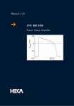
Electrophysiology
Electrochemistry
EPC 800 USB
Patch Clamp Amplifier
If you believe your job is to
make new discoveries...
…discover the EPC 800:
• Patch clamp amplifier with manual or computer controlled operation via USB
• Can be used with any data
acquisition interface with
compatible acquisition soft-
ware
• Low noise headstage optimized for single channel & whole-cell recordings
• True current clamp mode for fast AP recordings
• Automatic or manual
capacitance compensation
HEKA provides the finest instruments today
to achieve the needed progress of tomorrow…
1
EPC 800
Patch Clamp Amplifier
For any researcher who desires manual user control through knobs
and dials, while at the same time, longs for some degree of computer
communication and automatic control, HEKA is excited to release the
EPC 800 USB. This amplifier is truly a unique hybrid patch-clamp amplifier with its design and feature-set primarily based upon the manually controlled EPC 8. The EPC 800 USB is the most flexible patch
clamp amplifier HEKA has ever produced in that it is a stand-alone
amplifier that can be combined with any existing AD/DA interface and
its compatible acquisition software.
Improvements in comparison to the EPC 8:
• Telegraphing outputs for Gain, Bandwidth, Mode & C-Slow
• Automatic Vp-Offset, C-Fast & C-Slow compensation with the simple push of a button
• Improved current monitor filters
• USB 2.0 communication for software control of all amplifier
functions
• Low Frequency Voltage Clamp Mode (LFVC)
• CC+Bridge Mode
• Improved RS Comp Ranges
2
Electrophysiology
Features
Operating Modes of the EPC 800 USB
The EPC 800 USB can be operated in three modes: Local, Local + Telegraphing and Remote. The
decision of which mode to use not only depends on user preference of whether or not to have the
functionality to turn knobs and switches, but also on what data acquisition software and interface the
EPC-800 USB is used with.
1. Local:
• Manual control by use of the knobs and switches on the front panel.
• Vp-Offset, C-Fast and C-Slow compensation can be performed manually or automatically with the push of a button.
• Amplifier can be used with ANY data acquisition interface and its compatible software.
2. Local + Telegraphing:
• Telegraphing outputs on the rear panel for Gain, Filter Bandwidth, Mode and C-Slow.
Telegraphing features can be utilized by use with ANY AD/DA interface having telegraphing inputs.
• Amplifier remains under manual control with use of the knobs and switches on the front panel.
• Ability to perform automatic adjustments of Vp-Offset, C-Fast and C-Slow compensations are
still possible.
3. Remote:
• Commands are sent and received through USB 2.0 communication.
• The EPC 800 USB commands are open source and users are free to write their own interfacing
to the device.
• HEKA offers a dynamic link library (DLL) providing direct access to the amplifier and HEKA
data acquisition interfaces.
• HEKA’s PATCHMASTER software supports all amplifier functionality in remote mode.
• Amplifier can also be used with HEKA’s EPCMASTER software in combination with custom
software or third-party software with the appropriate interface.
• Front panel knobs and switches of the amplifier are inactive, with the exception of the
LCD multi-position switch.
3
EPC 800
Patch Clamp Amplifier
Acquisition Software Options
1. Clampex software:
The EPC 800 USB can be used with pCLAMP / Clampex software.
Using pCLAMP requires the use of one of the series of Digidata
interfaces. Use with older models such as the 1200 require the
amplifier to be used in local mode. Use with more recent models
such as the Digidata 1440A, that are equipped with telegraphing
inputs, enable the EPC 800 USB to be used in a local + telegraphing
mode. In this situation, the filter, gain and C-Slow values are telegraphed and displayed within Clampex.
In local or local + telegraphing modes, the automatic C-Fast and
C-Slow compensations features of the EPC 800 USB can be utilized.
These are performed manually through the front panel and the
results clearly illustrated in the Membrane Test panel of Clampex.
2. PATCHMASTER software:
HEKA’s PATCHMASTER software fully supports the EPC 800 USB in both local and remote modes of
operation on either Windows (7, 2000, XP and VISTA) or Mac OS X operating systems. When using
PATCHMASTER, the amplifier can be combined with any one of the HEKA / InstruTECH series of interfaces (ITC-16, ITC-18, ITC-1600, LIH-1600, LIH 8+8).
When configured in Local mode, the amplifier operates manually with the front panel knobs and
switches of the EPC 800 USB all active. As controls are changed, the same values that are displayed on
the front panel LCD display are read and displayed in the PATCHMASTER amplifier window.
4
Electrophysiology
When in Remote mode, the
controls and knobs of the
EPC 800 USB are inactive. All
amplifier settings, including
automatic capacitance compensations, are fully controlled
through the software. One of
the many powerful features of
PATCHMASTER is that it enables
automatic control of the amplifier
through user-defined protocols.
Detailed information regarding
PATCHMASTER functionality can
be found in the PATCHMASTER
brochure and user’s manual.
3. EPCMASTER software
HEKA’s EPCMASTER software consists of a virtual front panel of the EPC 800 USB. Although the
program has no functions for data acquisition or analysis, it is very useful in that it provides users the
option of setting amplifier parameters from a software panel instead of manually using the front panel
controls. EPCMASTER is provided free of charge and should be used in conjunction with a custom data acquisition system i.e. IGOR Pro, Labview, pCLAMP, etc. The end result is a software controlled version of
the amplifier that is extremely flexible with regard what particular data acquisition interface or software
package it is being used with. This flexibility allows users to easily add an EPC 800 USB to their current
setups without the need to purchase or learn a new data acquisition package.
In this example, EPCMASTER
is being used with a Digidata
1440A and Clampex software,
the EPC 800 USB is now considered to be operated in remote
mode.
4. Custom software
The EPC 800 USB is flexible enough so that it can be integrated into customized experimental systems.
The amplifier USB commands are open source and users are free to write their own interfacing to the
device. HEKA provides a dynamic link library (DLL) which gives access to the amplifier and HEKA data
acquisition interfaces. The DLL can be used with most programming languages, such as C, Pascal,
Delphi and Visual Basic.
5
EPC 800
Patch Clamp Amplifier
Acquisition Modes
Three operating modes are provided: Voltage Clamp (VC), Current Clamp+Bridge (CC+Bridge) and Low
Frequency Voltage Clamp (LFVC).
Voltage Clamp (VC) mode recordings, ideal for recordings from whole-cell, cell-attached, single channel, loose patch or bilayer configurations.
The current clamp mode of the EPC 800 USB is called CC + Bridge. Bridge compensation in current
clamp mode acts in a similar way as RS compensation does in voltage clamp mode. It can be thought
of as an enhanced current clamp mode that fully compensates the voltage drop via the series (access)
resistance of the electrode (RS). In this mode, the stimulus artifact that is typically generated when
injecting current is fully eliminated. The current clamp circuitry of the EPC 800 USB acts as a voltagefollower, thereby increasing the speed and stability of the circuit. Recording and following rapid events
such as fast action potentials (AP) with patch or intracellular electrodes is possible.
The “Low Frequency Voltage Clamp” (LFVC) mode is a modified current clamp mode that allows
for the measurement of potential deflections such as action potentials or synaptic potentials, while
the average potential is kept constant at a value chosen by the user with the LFVCHOLD potentiometer.
The circuit thus works like a current clamp for fast signals and like a voltage clamp for low frequency
signals. To achieve this, the measured membrane potential is low-pass filtered and compared to the
LFVCHOLD potential. Current is injected into the cell to keep the membrane potential at the chosen LFVC
potential. There are five time constants (1, 3, 10, 30 and 100) available for the LFVC mode that specifiy
the speed of regulation. The feedback speed is highly dependent on the Gain Range settings.
C-Fast and C-Slow Compensation
Both C-Fast and C-Slow compensation routines can either be performed manually by turning the knobs
or automatically by pressing the Auto buttons on the front panel. Both C-Fast and C-Slow compensation can be applied in all three headstage gain ranges. The C-Fast range is 0 to 15 pF in all gain ranges.
C-Slow has 30, 100 and 1000 pF ranges.
Multi-parameter Display
An LCD panel can display the following parameter pairs: I / VMon, C-Fast / τ-fast, C-Slow / R-Series, RS
Range / Comp, VP / LFVC, I / VHold, and Noise. The displayed parameters can either be individually
selected via a multi-position switch or automatically set. If the Auto display mode is activated, the LCD
panel will automatically display the value of the control as its modified by the user.
Holding Potentials and VpOffset
Ten-turn potentiometers are available on the front panel for VPOFFSET (± 200 mV), VHOLD (± 500 mV),
IHOLD (± 50 nA or ± 500 pA) and LFVCHOLD (± 200 mV). VPOffset can be adjusted either manually or
automatically by pressing the Auto button.
6
Electrophysiology
Technical Specifications
General
Output Gain
Included Accessories
EPC 800 USB Headstage:
EPC 800 USB Model Circuit:
EPC 800 USB Manual:
Pipette Holder:
USB Cable: Power Cord:
1
1
1
1
1
1
Dimensions Main Unit
D x W x H: (31.1 x 48.3 x 14.5) cm / (12.3 x 19 x 5.7) inch
Weight Main Unit
11.4 kg (24.8 lbs)
(1.5 mm is standard, other diameters available upon request at no additional charge)
(3 meter USB 2.0 shielded cable)
(2 meter IEC type shielded)
Power Supply
Power requirements are 125 W. The logic controlled power supply
automatically switches the voltage range. Operational range is from
90-130V or 210-250V at line frequencies of 50 or 60 Hz.
A shielded transformer minimizes noise pickup from the power line
frequencies.
Ground Lines
Signal ground (GND) is isolated from the chassis by a 10 Ω resistor to
avoid ground loops. GND is accessible via a Banana plug on the front
panel and also via a connector on the headstage.
A Chassis ground (CHAS) is accessible via a Banana plug on the front
panel and is connected to the ground line of the power cord.
Headstage
Dimensions:
Resistors:
low gain range:
medium gain range:
high gain range: D x W x H: (90 x 16.9 x 14.3) mm
(3.54 x 0.67 x 0.57) inch
Three feedback resistors. Gain ranges can be switched during the experiment.
5 MOhm,± 2 μA current range
500 MOhm, ± 20 nA current range
50 GOhm, ± 200 pA current range
Bandwidth (max):
medium & low ranges: 100 kHz
high range: 60 kHz
Noise:
(measured with an open input, 8-pole Bessel filter and 50 GΩ resistor)
DC to 1 kHz < 0.03 pA RMS
DC to 3 kHz < 0.08 pA RMS
DC to 10 kHz < 0.225 pA RMS
Filters
The EPC 800 USB has a filter knob on the front panel with settings
of 0.1, 0.3, 0.5, 0.7, 1, 3, 5, 7, 10, 30 and 100 kHz. It is an integrated
filter comprised of two built-in filters for the current monitor signal.
Filter 1 is a 5-pole, 10 to 100 kHz Bessel pre-filter. Filter 2 is a 4-pole,
tunable 20 kHz Bessel filter. When the front panel knob is set to
either 30 or 100 kHz, filter 2 is bypassed and the signal is straight
filter 1. All of the other filter knob settings are filter 1 + filter 2.
low gain range:
medium gain range:
high gain range:
0.005, 0.01, 0.02, 0.05, 0.1, 0.2 mV/pA
0.5, 1, 2, 5, 10, 20 mV/pA
50, 100, 200, 500, 1000, 2000 mV/pA
Pipette Offset
± 200 mV (automatic or manual adjustment)
Holding Commands
Voltage Clamp:
± 500 mV with front panel knob
± 1 V via external Stim Input
Current Clamp + Bridge:
Low CC Output Gain Range: IHOLD = ± 50 nA
IMAX = ± 100 nA
(available when switching from VC mode in low gain range)
CC Stim Scaling = 10 pA
High CC Output Gain Range: IHOLD = ± 500 pA
IMAX = ± 1 nA
(available when switching from VC mode in either medium or high gain ranges)
CC Stim Scaling = 0.1 pA
Low Frequency Voltage Clamp (LFVC):
± 200 mV
τ of 1, 3, 10, 30 or 100
Capacitance Compensation
C-Fast Compensation:
0 ⇔ 15 pF, 0 ⇔ 8 μs tau
Automatic or manual compensation in all gain ranges
C-Slow Compensation:
Automatic or manual compensation in all gain ranges.
OFF / 30, 100, 1000 pF switch
30 pF range (1.0 ⇔ 30 pF)
100 pF range (1.0 ⇔ 100 pF)
1000 pF range (1.0 ⇔ 1000 pF)
Injection Capacitors:
The C-Fast compensation signal is injected via a 1 pF capacitor. The
C-Slow compensation signals are injected via a 10 pF capacitor in
medium and low gain and via a 1 pF capacitor in high gain range
R-Series:
0.1 MΩ ⇔ 200 MΩ (1000 pF range)
1 MΩ ⇔ 200 MΩ (100 pF range)
5 MΩ ⇔ 200 MΩ (30 pF range)
Series Resistance Compensation
Manual adjustment with range depending on cell capacitance.
Equivalent Time Constants: 2 μs / 10 μs / 100 μs
Range:
0 ⇔ 95%
In current clamp mode:
RS Comp serves as Bridge Compen sation with a range of 0 ⇔ 120%
Telegraphing Outputs
(BNC connections on rear panel)
Gain, Filter Bandwidth, Amplifier Mode, C-Slow
7
Electrophysiology
HEKA Elektronik
Dr. Schulze GmbH
Wiesenstraße 71
D-67466 Lambrecht/Pfalz
Germany
Phone
Fax
Web Site
Email
+49 (0) 63 25 / 95 53-0
+49 (0) 63 25 / 95 53-50
http://www.heka.com
[email protected]
[email protected]
HEKA Electronics Incorporated
47 Keddy Bridge Road
R.R. #2
Mahone Bay, NS B0J 2E0
Canada
Phone
Fax
Web Site
Email
+1 902 624 0606
+1 902 624 0310
http://www.heka.com
[email protected]
[email protected]
HEKA Instruments Inc.
2128 Bellmore Avenue
Bellmore, New York 11710-5606
USA
Phone
Fax
Web Site
Email
+1 516 882 1155
+1 516 467 3125
http://www.heka.com
[email protected]
[email protected]
VKRPK1/1
General notice:
Product names used herein
are for identification purposes
only and may be trademarks of
their respective owners. HEKA
disclaims any and all rights in
those marks.
8
Electrochemistry
We reserve the right to effect
technical changes as development progresses. Special versions are available on request.
Further technical data are provided by a detailed description,
which is available on request.
A guarantee of one year applies
on all instruments.


![HEMA_Schrift-Anschnitt [Konvertiert]](http://vs1.manualzilla.com/store/data/006102622_1-2335e6c1d5fc3f6a8f0ec139ee8644f2-150x150.png)