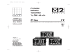
1
on
l
in
ec
om
po
ne
nt
s.
co
m
AUTOMATIONWORX
User Manual
UM EN IB IL TEMPCONTROL 300
Order No.: 2888657
Engineering Tool for Multi-Channel Temperature
Controllers Supporting Modular Extension
IB IL TEMPCON 300 RTD/UTH …
s.
nt
ne
po
om
in
ec
on
l
co
m
AUTOMATIONWORX
User Manual
01/2007
UM EN IB IL TEMPCONTROL 300
Revision:
00
Order No.:
2888657
Designation
om
in
ec
This user manual is valid for:
po
ne
Designation:
nt
s.
co
m
Engineering Tool for Multi-Channel Temperature Controllers
Supporting Modular Extension IB IL TEMPCON 300 RTD/UTH …
Version
Order No.
1.6
2819370
IB IL TEMPCON 300 RTD-PAC
10/20
2819668
IB IL TEMPCON 300 RTD-2MBD-PAC
10/20
2819820
on
l
IB IL TEMPcontrol
for configuring the multi-channel temperature controllers
IB IL TEMPCON 300 RTD-B-PAC
10/20
2819590
IB IL TEMPCON 300 RTD-B-2M-PAC
10/20
2819859
IB IL TEMPCON 300 UTH-PAC
10/20
2819671
IB IL TEMPCON 300 UTH-2MBD-PAC
10/20
2819833
IB IL TEMPCON 300 UTH-B-PAC
10/20
2819613
IB IL TEMPCON 300 UTH-B-2M-PAC
10/20
2819846
7270_en_00
PHOENIX CONTACT
IB IL TEMPcontrol
Please Observe the Following Notes
In order to ensure the safe use of the product described, we recommend that you read this
manual carefully. The following notes provide information on how to use this manual.
User Group of This Manual
The use of products described in this manual is oriented exclusively to qualified application
programmers and software engineers, who are familiar with the safety concepts of
automation technology and applicable standards.
co
m
Phoenix Contact accepts no liability for erroneous handling or damage to products from
Phoenix Contact or third-party products resulting from disregard of information contained
in this manual.
Explanation of Symbols Used
s.
The attention symbol refers to an operating procedure which, if not carefully followed, could
result in damage to hardware and software or personal injury.
ne
nt
The note symbol informs you of conditions that must be strictly observed to achieve errorfree operation. It also gives you tips and advice on the efficient use of hardware and on
software optimization to save you extra work.
po
The text symbol refers to detailed sources of information (manuals, data sheets, literature,
etc.) on the subject matter, product, etc. This text also provides helpful information for the
orientation in the manual.
We Are Interested in Your Opinion
om
We are constantly striving to improve the quality of our manuals.
Should you have any suggestions or recommendations for improvement of the contents
and layout of our manuals, please send us your comments.
on
l
in
ec
PHOENIX CONTACT GmbH & Co. KG
Documentation Services
32823 Blomberg
Germany
PHOENIX CONTACT
Phone
Fax
E-mail
+49 - (0) 52 35 30 0
+ 49 - (0) 52 35 34 18 08
[email protected]
7270_en_00
IB IL TEMPcontrol
General Terms and Conditions of Use for Technical Documentation
Phoenix Contact GmbH & Co. KG reserves the right to alter, correct, and/or improve the
technical documentation and the products described in the technical documentation at its
own discretion and without giving prior notice, insofar as this is reasonable for the user.
The same applies to any technical changes that serve the purpose of technical progress.
nt
s.
co
m
The receipt of technical documentation (in particular data sheets, installation instructions,
manuals, etc.) does not constitute any further duty on the part of
Phoenix Contact GmbH & Co. KG to furnish information on alterations to products and/or
technical documentation. Any other agreement shall only apply if expressly confirmed in
writing by Phoenix Contact GmbH & Co. KG.
Please note that the supplied documentation is product-specific documentation only and
that you are responsible for checking the suitability and intended use of the products in
your specific application, in particular with regard to observing the applicable standards
and regulations.
Although Phoenix Contact GmbH & Co. KG makes every effort to ensure that the
information content is accurate, up-to-date, and state-of-the-art, technical inaccuracies
and/or printing errors in the information cannot be ruled out.
Phoenix Contact GmbH & Co. KG does not offer any guarantees as to the reliability,
accuracy or completeness of the information.
All information made available in the technical data is supplied without any accompanying
guarantee, whether expressly mentioned, implied or tacitly assumed.
po
ne
Phoenix Contact GmbH & Co. KG accepts no liability or responsibility for errors or
omissions in the content of the technical documentation (in particular data sheets,
installation instructions, manuals, etc.).
on
l
in
ec
om
The aforementioned limitations of liability and exemptions from liability do not apply, in so
far as liability must be assumed, e.g., according to product liability law, in cases of
premeditation, gross negligence, on account of loss of life, physical injury or damage to
health or on account of the violation of important contractual obligations. Claims for
damages for the violation of important contractual obligations are, however, limited to
contract-typical, predictable damages, provided there is no premeditation or gross
negligence, or that liability is assumed on account of loss of life, physical injury or damage
to health. This ruling does not imply a change in the burden of proof to the detriment of the
user.
7270_en_00
PHOENIX CONTACT
IB IL TEMPcontrol
Statement of Legal Authority
This manual, including all illustrations contained herein, is copyright protected. Use of this
manual by any third party is forbidden. Reproduction, translation, and public disclosure, as
well as electronic and photographic archiving or alteration requires the express written
consent of Phoenix Contact. Violators are liable for damages.
Phoenix Contact reserves all rights in the event of a patent being granted, in as far as this
concerns software of Phoenix Contact that meets the criteria of technicity or has technical
relevance. Third-party products are always named without reference to patent rights. The
existence of such rights shall not be excluded.
Windows 3.x, Windows 95, Windows 98, Windows NT, Windows 2000, and Windows XP
are trademarks of the Microsoft Corporation.
m
All other product names used are trademarks of the respective organizations.
co
Internet
Up-to-date information on Phoenix Contact products can be found on the Internet at:
s.
www.phoenixcontact.com
nt
Make sure you always use the latest documentation. It can be downloaded at:
ne
www.download.phoenixcontact.com
A conversion table is available on the Internet at:
on
l
in
ec
om
po
www.download.phoenixcontact.com/general/7000_en_00.pdf
PHOENIX CONTACT
7270_en_00
Table of Contents
Functions of Multi-Channel Temperature Controllers .............................................................1-1
1.1
Function Overview ............................................................................................. 1-3
1.1.1
Multi-Channel Temperature Controllers That Support
Modular Extension .............................................................................. 1-4
1.1.2
IB IL TEMPcontrol Engineering Tool .................................................. 1-4
1.1.3
Software-Supported System Configuration ........................................1-4
1.1.4
Control and Actuator Functions .......................................................... 1-4
1.1.5
Input and Output Functions ................................................................ 1-5
1.1.6
Offline Self-Tuning .............................................................................. 1-5
1.1.7
Self-Tuning During Operation
(Self-Tuning at the Setpoint) ...............................................................1-5
1.1.8
Startup Circuit .....................................................................................1-6
1.1.9
Controlled Heating .............................................................................. 1-6
1.1.10 Second Setpoint and Ramp Function .................................................1-6
1.1.11 Boost Function .................................................................................... 1-6
1.1.12 Monitoring Functions ..........................................................................1-7
1.1.13 Alarm and Safety Functions, Alarm Outputs ......................................1-8
1.1.14 Flexible Scanning Rates From 100 ms ............................................... 1-8
1.1.15 Measured Value Correction ................................................................ 1-9
1.1.16 Mass Pressure Acquisition for Extrusion Systems .............................1-9
1.1.17 Function Control via Digital Inputs ......................................................1-9
1.1.18 Signal Wiring ...................................................................................... 1-9
1.1.19 Forcing ................................................................................................1-9
1.1.20 Watchdog .........................................................................................1-10
1.2
Description of the Controller Functions ............................................................ 1-10
1.2.1
Input .................................................................................................. 1-11
1.2.2
Functions .......................................................................................... 1-12
1.2.3
Output ...............................................................................................1-14
in
ec
om
po
ne
nt
s.
co
m
1
Self-Tuning .......................................................................................................1-17
1.3.1
Tuning During Startup ...................................................................... 1-18
1.3.2
Tuning at the Setpoint ...................................................................... 1-18
1.3.3
Tuning During Startup and at the Setpoint .......................................1-18
1.3.4
Step Attempt During Startup .............................................................1-20
1.3.5
Pulse Attempt During Startup ........................................................... 1-20
1.3.6
Sequence for Tuning at the Setpoint ................................................ 1-20
1.3.7
Tuning at the Setpoint for Motor Step Controllers ............................ 1-21
1.3.8
Starting Self-Tuning .......................................................................... 1-22
1.3.9
Aborting Self-Tuning ......................................................................... 1-22
1.3.10 Examples for Self-Tuning Attempts (Inverse Controller,
Heating or Heating/Cooling) .............................................................1-23
1.4
Startup Circuit .................................................................................................. 1-27
1.5
Controlled Setpoint Modification ...................................................................... 1-29
1.5.1
Priorities for Controlled Setpoint Modification ................................... 1-29
1.5.2
Representation of Controlled Setpoint Modification .........................1-30
on
l
1.3
7270_en_00
PHOENIX CONTACT
i
IB IL TEMPcontrol
Heating Current Monitoring (HC Alarm) ........................................................... 1-32
1.7
Closed-Loop Control Circuit Monitoring (Loop Alarm)......................................1-36
1.8
Motor Step Controller ....................................................................................... 1-38
Initial Steps for the Engineering Tool ......................................................................................2-1
Product Description for the Engineering Tool..................................................... 2-1
2.2
System Requirements ........................................................................................2-2
2.3
Additional Documentation ..................................................................................2-2
2.4
Installing the Program ........................................................................................2-2
2.5
Connecting Devices ...........................................................................................2-2
2.6
Starting the Program .......................................................................................... 2-3
2.7
Exiting the Program............................................................................................ 2-3
m
2.1
co
2
1.6
Program Interface ...................................................................................................................3-1
4
Program Functions .................................................................................................................4-1
nt
s.
3
Starting the Program .......................................................................................... 4-1
4.2
"Device Selection" Window ................................................................................4-2
4.3
"Project Info" Window......................................................................................... 4-3
4.4
"Connection Wizard" Window.............................................................................4-4
4.4.1
System Configuration ......................................................................... 4-4
4.4.2
Controller ............................................................................................ 4-8
4.4.3
Inputs .................................................................................................. 4-9
4.4.4
Changeover Signals ......................................................................... 4-11
4.4.5
Outputs ............................................................................................. 4-13
4.4.6
Common Alarms ............................................................................... 4-17
on
l
in
ec
om
po
ne
4.1
ii
PHOENIX CONTACT
4.5
"Parameter" Window ........................................................................................ 4-18
4.5.1
"Configuration" Folder ...................................................................... 4-22
4.5.2
"Parameter" Folder ...........................................................................4-52
4.6
"Output Assignments" Window......................................................................... 4-81
4.7
"Simulation" Window ........................................................................................ 4-82
4.7.1
Input and Output Fields .................................................................... 4-83
4.7.2
Toolbar ............................................................................................. 4-83
4.7.3
Status Bar .........................................................................................4-83
4.7.4
"Process Parameters" Dialog Box ....................................................4-84
4.7.5
"Disturbance" Dialog Box ................................................................. 4-85
4.8
"Operation" Window .........................................................................................4-87
7270_en_00
Table of Contents
4.9
Menus .....................................................................................................................................5-1
"File" Menu .........................................................................................................5-1
5.2
"Edit" Menu.........................................................................................................5-3
5.3
"View" Menu ....................................................................................................... 5-4
5.4
"Device" Menu.................................................................................................... 5-5
5.5
"Extras" Menu..................................................................................................... 5-6
5.5.1
"Language" Menu Item .......................................................................5-6
5.5.2
"Options" Menu Item ........................................................................... 5-6
5.6
"Window" Menu .................................................................................................. 5-8
5.7
"Help" Menu ....................................................................................................... 5-8
nt
s.
co
m
5.1
ne
5
"Trend" Window................................................................................................ 4-93
4.9.1
Text Area .......................................................................................... 4-94
4.9.2
Graphical Area .................................................................................. 4-94
4.9.3
Toolbar ............................................................................................. 4-94
4.9.4
Status Bar .........................................................................................4-95
4.9.5
"Trend Settings" Dialog Box .............................................................4-95
Ordering Data ........................................................................................................................ A-1
B
Appendices............................................................................................................................. B-1
B2
List of Tables ..................................................................................................... B-5
Index ................................................................................................................. B-7
on
l
in
ec
B3
List of Figures.................................................................................................... B-1
om
B1
po
A
7270_en_00
PHOENIX CONTACT
iii
on
l
in
ec
om
po
ne
nt
s.
co
m
IB IL TEMPcontrol
iv
PHOENIX CONTACT
7270_en_00
Functions of Multi-Channel Temperature Controllers
1
Functions of Multi-Channel Temperature Controllers
m
The IB IL TEMPcontrol engineering tool is used to configure, start up, and diagnose multichannel temperature controllers that support modular extension:
– IB IL TEMPCON 300 RTD-PAC (Order No. 2819668)
– IB IL TEMPCON 300 RTD-2MBD-PAC (Order No. 2819820)
– IB IL TEMPCON 300 RTD-B-PAC (Order No. 2819590)
– IB IL TEMPCON 300 RTD-B-2M-PAC (Order No. 2819859)
– IB IL TEMPCON 300 UTH-PAC (Order No. 2819671)
– IB IL TEMPCON 300 UTH-2MBD-PAC (Order No. 2819833)
– IB IL TEMPCON 300 UTH-B-PAC (Order No. 2819613)
– IB IL TEMPCON 300 UTH-B-2M-PAC (Order No. 2819846)
nt
s.
co
As well as compact multi-channel temperature controllers:
– IB IL TEMPCON RTD (Order No. 2819244)
– IB IL TEMPCON RTD-PAC (Order No. 2861771)
– IB IL TEMPCON UTH (Order No. 2819312)
– IB IL TEMPCON UTH-PAC (Order No. 2861807)
ne
IB IL TEMPCON 300 RTD-PAC and IB IL TEMPCON 300 RTD-B-PAC, and
IB IL TEMPCON 300 UTH-PAC and IB IL TEMPCON 300 UTH-B-PAC only differ with
regard to the number of control channels.
po
The ...-2MBD... and ...-2M... versions operate at a transmission speed of 2 Mbps within
the Inline station, while all other multi-channel temperature controllers operate at
500 kbps.
om
For greater clarity, the order designations IB IL TEMPCON 300 RTD-PAC and
IB IL TEMPCON 300 UTH-PAC are used throughout this document.
on
l
in
ec
The user interface of the IB IL TEMPcontrol program differs for
IB IL TEMPCON 300 RTD/UTH … multi-channel temperature controllers that support
modular extension and IB IL TEMPCON RTD/UTH … compact multi-channel
temperature controllers.
7270_en_00
This user manual only describes the versions that support modular extension. For
information on operating the engineering tool with compact versions, please refer to the
IB IL TEMPCONTROL UM E user manual (Order No. 2698915).
PHOENIX CONTACT
1-1
IB IL TEMPcontrol
Type
Order No.
Description
IB IL TEMPCON 300 RTD-PAC
2819668
Six closed-loop control circuits with six inputs for resistance
thermometers, one input for the total current measurement of
heating elements, six digital outputs, supports modular extension
by up to 30 closed-loop control circuits
2819590
IB IL TEMPCON 300 RTD-B-2M-PAC
2819859
IB IL TEMPCON 300 UTH-PAC
2819671
IB IL TEMPCON 300 UTH-2MBD-PAC 2819833
2819613
IB IL TEMPCON 300 UTH-B-2M-PAC
2819846
Eight closed-loop control circuits with eight inputs for
thermocouples, one input for the total current measurement of
heating elements, eight digital outputs, supports modular
extension by up to 30 closed-loop control circuits
Four closed-loop control circuits with four inputs for
thermocouples, one input for the total current measurement of
heating elements, eight digital outputs, cannot be extended
s.
IB IL TEMPCON 300 UTH-B-PAC
Four closed-loop control circuits with four inputs for resistance
thermometers, one input for the total current measurement of
heating elements, six digital outputs, cannot be extended
m
IB IL TEMPCON 300 RTD-B-PAC
co
IB IL TEMPCON 300 RTD-2MBD-PAC 2819820
on
l
in
ec
om
po
ne
nt
For additional technical information, please refer to the terminal-specific data sheets.
They are available on the Internet at www.download.phoenixcontact.com.
1-2
PHOENIX CONTACT
7270_en_00
Functions of Multi-Channel Temperature Controllers
1.1
Function Overview
Inline multi-channel temperature controllers are precise and compact multi-channel
controllers based on microcontrollers, which are used for control tasks in numerous sectors
of industry. They enable you to select simple on/off closed-loop control with a threshold
value switch, digital PID closed-loop control or motor step closed-loop control for each
channel. In addition to the multi-channel controllers that support modular extension
(IB IL TEMPCON 300 RTD/UTH … with up to 30 closed-loop control circuits), controllers
are also available in a compact design.
co
m
A number of features help to considerably increase the control quality, cost-effectiveness,
and operational reliability of supply and production processes. Two integrated procedures
for automatic self-tuning ensure optimum control behavior and short startup times.
Measuring circuit monitoring with its corresponding manual mode function ensures
optimum availability of the control processes.
A user-friendly graphic startup tool, the IB IL TEMPcontrol engineering tool, simplifies the
operation, visualization, and diagnostics of these multi-channel temperature controllers.
po
ne
nt
s.
The multi-channel temperature controller is the core component of the modular multicontroller system. Thanks to the modular system concept, various input and output signals
can be supported. The IB IL TEMPCON 300 ... controller itself is equipped with onboard
inputs and outputs for up to eight controllers. The inputs are available for thermocouples
or for resistance thermometers, the outputs supply 24 V digital signals. These signals
output the continuous manipulated variable of the controller using the pulse/pause ratio
and are controlled with the typical solid-state relay for electrical heaters; or the digital
outputs output the "open" and "close" signal for direct control of a proportional valve with
servomotor. Other I/O signals can be connected to the multi-channel temperature
controllers via corresponding Inline extension terminals.
om
The integrated sensor, heating current, and closed-loop control circuit monitoring is used
to diagnose errors in the overall controlled system.
in
ec
The head of the system is a bus coupler, which enables coupling to various fieldbus
systems. The power supply for the system is also integrated in this bus coupler. In large
systems, a power terminal can be used to cover a higher current requirement for I/O
devices.
on
l
If the current requirement for the logic and/or the analog voltage is exceeded, another
power terminal must be inserted.
7270_en_00
PHOENIX CONTACT
1-3
IB IL TEMPcontrol
1.1.1
Multi-Channel Temperature Controllers That Support
Modular Extension
m
The IB IL TEMPCON 300 RTD-PAC and IB IL TEMPCON 300 UTH-PAC multi-channel
temperature controllers can operate up to six or eight closed-loop control circuits. By
inserting additional temperature measurement terminals (IB IL TEMP …), the system can
be extended by up to a maximum of 30 closed-loop control circuits. The number of
temperature measurement terminals used need be no more than the number of actual
inputs or outputs. A maximum of 60 outputs (analog or digital), 34 analog inputs, and
320 digital inputs can be processed per multi-channel temperature controller. In the
IB IL TEMPcontrol engineering tool, the Inline station must be configured according to the
structure (see Section 4.4, ""Connection Wizard" Window" on page 4-4).
co
IB IL TEMPCON 300 RTD-B-PAC and IB IL TEMPCON 300 UTH-B-PAC can also be
extended by additional temperature measurement terminals. The number of control
channels is always limited to four.
IB IL TEMPcontrol Engineering Tool
nt
s.
1.1.2
po
ne
The IB IL TEMPcontrol engineering tool, which is used to configure, start up, and diagnose
multi-channel temperature controllers, is available as PC software for Windows 2000 and
Windows XP. A notebook equipped with the engineering tool is connected to the controller
via a V.24 (RS-232) interface. IB IL TEMPcontrol also includes clear configuration and
monitoring of the controller system as well as a controller and system simulation.
Software-Supported System Configuration
om
1.1.3
on
l
in
ec
When creating a TEMPCON 300 station, in addition to IB IL TEMPCON 300 RTD-PAC or
IB IL TEMPCON 300 UTH-PAC there are around 20 different Inline I/O terminals to
choose from. The IB IL TEMPcontrol engineering tool can be used to freely adjust the
number of desired closed-loop control circuits (maximum of 30) as well as the combination
of input and output signal types. The system can of course also be configured via the
fieldbus.
Digital Inline extension terminals with two to 16 digital inputs or outputs and analog Inline
extension terminals with one to eight digital inputs or outputs can be selected.
The multi-channel temperature controller automatically checks whether the system
configuration specified via IB IL TEMPcontrol or the fieldbus corresponds to the terminals
that are actually connected.
1.1.4
Control and Actuator Functions
The multi-channel temperature controller can be configured as a signaling device
(threshold value switch with hysteresis), 2-step PID controller, 3-step PID controller, 3-step
PID controller with water evaporation cooling, cascade controller or motor step controller.
In addition, a design as a controller with constant or split signal output (split range) is
possible and bumpless automatic/manual switch-over is available. In manual mode, the
actuator output can be set to any output value.
1-4
PHOENIX CONTACT
7270_en_00
Functions of Multi-Channel Temperature Controllers
1.1.5
Input and Output Functions
IB IL TEMPCON 300 ... controllers are primarily designed to control thermal processes.
Inputs are therefore available for thermocouples (UTH) or for resistance thermometers
(RTD). On the output side, the multi-channel temperature controllers output a continuous
manipulated variable, which is then output via 24 V outputs so that either the solid-state
relays for electrical heaters or proportional valves with servomotor (control valves) are
controlled.
m
To control the solid-state relays, the outputs convert the analog manipulated variable into
a square-wave signal with variable pulse/pause ratio between 0% and 100%. The cycle
time can be set between 0.4 s and 3200 s. This type of control is designed for heating
elements that display corresponding integrational behavior for the heat energy.
Offline Self-Tuning
nt
1.1.6
s.
co
One disadvantage of this feature is that very small or large manipulated variables result in
very short pulse or pause times, which subsequent contactors in particular cannot follow.
In order to prevent this, each output can extend the cycle time in the event of very small or
large manipulated variables. This function is referred to as "tuning of cycle time" and is
enabled by default (see page 4-38 and page 4-61).
po
ne
Offline self-tuning automatically determines the optimum control parameters. This
procedure is activated on request (via the fieldbus or engineering tool) and calculates the
optimum parameters for fast adjustment to the setpoint without overshoot using the delay
time Tu and the rate of change of the controlled system vmax. If a controller has been
configured as a 3-step controller, the self-tuning procedure determines the "cooling"
parameters separately. Self-tuning also operates in combination with the startup circuit.
in
ec
om
Offline self-tuning can be started individually for each channel or together for several
coupled closed-loop control circuits (maximum of 30). This means that optimum
parameters can even be determined for tightly coupled temperature systems. The closedloop control circuits can be combined into groups via the configuration. Using this
procedure, the closed-loop control circuits can be synchronized in up to four different
groups.
on
l
1.1.7
7270_en_00
Self-Tuning During Operation
(Self-Tuning at the Setpoint)
This procedure also determines the optimum control parameters at the setpoint, either on
request or automatically (with specified vibration gradient). Self-tuning at the setpoint
operates without vibrations and with only minimal controlled variable deviation.
PHOENIX CONTACT
1-5
IB IL TEMPcontrol
1.1.8
Startup Circuit
When using, e.g., high-performance heating cartridges with magnesium oxide as the
insulation material, these cartridges must be heated gradually during startup in order to
remove any humidity and to avoid damage. When a startup circuit is selected, the
controller first approaches the startup setpoint (e.g., 95°C) at the set startup
gradient (e.g., 40%). The startup setpoint is held during the selected startup hold time.
Thereafter, the controller approaches main setpoint W, without limiting the gradient.
1.1.9
Controlled Heating
Second Setpoint and Ramp Function
ne
1.1.10
nt
s.
co
m
Controlled heating is the synchronized heating of several closed-loop control circuits. This
function is intended to prevent thermal voltages within a group of heating zones. The multichannel temperature controller detects the zone with the lowest temperature and increases
the setpoint in set increments. Control zones at a higher temperature level wait for the
remaining zones so that controlled heating can be implemented simultaneously for all the
zones. In order to ensure synchronous heating, the multi-channel temperature controller
detects the zone with the lowest rate of rise and limits the increase of other setpoints in the
group to this value.
om
po
A second setpoint (e.g., the reduction setpoint) can be activated via any digital input or via
the fieldbus. Using a setpoint gradient function, which starts every time a setpoint is
modified or the system is restarted, every new setpoint is approached at the set gradient.
1.1.11
Boost Function
on
l
in
ec
The boost function temporarily increases the setpoint, e.g., in order to remove any
remaining material that has "frozen" to tool nozzles used in heating channel controllers.
1-6
PHOENIX CONTACT
7270_en_00
Functions of Multi-Channel Temperature Controllers
1.1.12
Monitoring Functions
Measuring Circuit Monitoring and Manual Mode Function in Response to Measuring
Circuit Errors (Accept Manipulated Variables in the Event of Sensor Break)
Measuring circuit monitoring and the corresponding manual mode function ensure
optimum operational reliability of the control processes.
m
The integrated measuring circuit monitoring checks the inputs for sensor and supply line
breaks, short circuit, and polarity reversal. When measuring circuit monitoring responds to
a fault in the measuring circuit, in addition to the alarms described below, one of the
following manual mode functions for the controller output can be selected in response:
– Pre-defined manipulated variable
– Set manipulated variable to "0" (disable outputs)
– Accept mean manipulated variable
ne
Limit Value Monitoring
nt
s.
co
This function enables production on a system to continue in the event of a measuring circuit
error (e.g., sensor break). The controller then executes the defined function in response to
the measuring circuit error (e.g., output of the mean manipulated variable) and indicates
the error via the fieldbus or at a digital output. As soon as a valid measured value is
detected by the multi-channel temperature controller, it automatically resumes controller
operation.
om
po
With limit value monitoring, one of the following measured values is monitored for
overrange or underrange:
– Actual value
– System deviation
– Setpoint
– Manipulated variable
Up to three limit values can be monitored per channel.
in
ec
The results of limit value monitoring can be output individually at the digital outputs or
together in group alarms, which can then be switched to an output.
on
l
Closed-Loop Control Circuit Monitoring (Loop Alarm)
7270_en_00
Closed-loop control circuit monitoring is used to check the operation of the entire closedloop control circuit. It can be used to detect a situation where a manipulated variable
modification does not result in the corresponding actual value. The alarm can be output,
e.g., via a digital output or as a group alarm.
PHOENIX CONTACT
1-7
IB IL TEMPcontrol
Heating Current Acquisition, Heating Current/Heating Element and Actuator
Monitoring
Every multi-channel temperature controller and every temperature measurement terminal
has an input for measuring the heating current, which can be used to monitor the heating
circuits that are switched via the outputs of the corresponding module.
m
For every eight heating zones (maximum), a current transformer can be connected to the
heating current input of the terminal. The converter signal is rectified on the multi-channel
temperature controller or on the temperature measurement terminal with heating current
input. In addition to acquiring the heating currents, the heating current limits are monitored
for overrange or underrange and the actuator (e.g., solid-state relay) is monitored for short
circuit. If a limit value violation is detected, this information can be output at a digital output
or as a group alarm.
co
Elimination of Heating Current Monitoring Errors Caused by Mains Voltage
Fluctuations
Alarm and Safety Functions, Alarm Outputs
ne
1.1.13
nt
s.
In order to prevent mains voltage fluctuations from affecting the evaluation of heating
current monitoring, the multi-channel temperature controller can be used to acquire the
mains voltage (one phase or all three phases separately). The switch-on threshold for the
heating current alarm is then adjusted according to the actual mains voltage.
on
l
in
ec
om
po
The multi-channel temperature controller features comprehensive alarm handling. Any
alarm signals can be output at digital outputs and/or supplied to the higher-level control
system via the fieldbus. In addition, any alarm messages can be combined via a maximum
of six group alarms. The following alarm messages are available for each channel:
– Relative measured value alarm for monitoring the system deviation (actual value setpoint)
– Absolute measured value alarm for monitoring limit values, regardless of the setpoint
setting
– Relative measured value alarm with alarm suppression (alarm is not active during
startup and in the event of setpoint modifications)
– Loop alarm (closed-loop control circuit monitoring)
– Measuring circuit alarm (sensor error alarm)
– Heating current alarm
1.1.14
Flexible Scanning Rates From 100 ms
The multi-channel temperature controller enables the scanning rate of the closed-loop
control circuit to be freely scaled within a fixed increment. A high degree of flexibility can
thus be achieved when adjusting to the connected systems. This means, for example, that
fast tool heaters can be combined without any problem with slow cylinder heaters. The
smallest adjustable scanning rate is 100 ms. Six closed-loop control circuits can be
detected and calculated, e.g., in 200 ms. IB IL TEMPcontrol offers a user-friendly setting
option for scanning rates for all channels and thus enables the optimum distribution of
CPU resources.
1-8
PHOENIX CONTACT
7270_en_00
Functions of Multi-Channel Temperature Controllers
1.1.15
Measured Value Correction
Measured value correction can be used to correct or scale the measurement. This can also
be performed online via a user-friendly operating page in the IB IL TEMPcontrol
engineering tool.
1.1.16
Mass Pressure Acquisition for Extrusion Systems
Function Control via Digital Inputs
co
1.1.17
m
The multi-channel temperature controller provides inputs for the direct connection of mass
pressure transducers on request.
Signal Wiring
po
1.1.18
ne
nt
s.
Digital inputs can be freely wired with the following functions for any control channels:
– Parameter record switch-over
– Shutdown of all controllers
– Switch-over to the second setpoint
– Boost activation for heating channels
– Automatic/manual switch-over
– Read via the fieldbus
om
Signal Wiring to Digital Outputs
in
ec
A maximum of 60 digital outputs can be "wired" to the following signals:
– Output signal of the controller for heating or cooling (manipulated variable), e.g., for
controlling the actuators using a square-wave signal with variable pulse/pause ratio or
for controlling motor-driven valves
– Any group alarm
– Control via the fieldbus
on
l
Signal Wiring to Analog Outputs
A maximum of 60 analog outputs can be "wired" to the following signals:
– Output signal of the controller for heating or cooling (manipulated variable)
– Output signal of the controller for heating only (manipulated variable)
– Output signal of the controller for cooling only (manipulated variable)
– Actual value (measuring transducer function)
– Setpoint
– Control via the fieldbus
1.1.19
Forcing
All digital and analog outputs not used for closed-loop control can be forced via the
fieldbus. All outputs can be read via the fieldbus.
7270_en_00
PHOENIX CONTACT
1-9
IB IL TEMPcontrol
1.1.20
Watchdog
The multi-channel temperature controller contains a hardware watchdog, which is
triggered internally every 0.25 s (maximum) and triggers a rest in the event of a terminal
firmware malfunction.
1.2
Description of the Controller Functions
s.
co
m
One or more controllers can be activated (up to 30, maximum) in the multi-channel
temperature controller. Each of these controllers is divided into the following function
blocks:
– Input
– Functions
– Output
– User interface
on
l
in
ec
om
po
ne
nt
Figure 1-1 illustrates the basic structure of these temperature controllers for processing
controller functions.
Figure 1-1
1-10
PHOENIX CONTACT
Block diagram
7270_en_00
Functions of Multi-Channel Temperature Controllers
1.2.1
Input
A controller input consists of two components:
– Measured value acquisition
– Signal preprocessing
Measured Value Acquisition
In measured value acquisition, input signals are acquired from the field and are converted
into measured values according to the set sensor type.
Signal Preprocessing
on
l
in
ec
om
po
ne
nt
s.
co
m
In signal preprocessing, the measured values are corrected and filtered before being
transmitted to the actual controller function.
7270_en_00
Figure 1-2
Block diagram of the inputs
PHOENIX CONTACT
1-11
IB IL TEMPcontrol
1.2.2
Functions
Closed-Loop Control System
The closed-loop control system influences the control algorithm according to the states.
The possible states include, for example:
– Automatic mode
– Self-tuning
– Manual mode
Closed-Loop Control
m
In closed-loop control, manipulated variable YPID is calculated using the selected controller
configuration and the set parameters.
co
Setpoint Processing
ne
nt
s.
Setpoint processing is responsible for the following functions:
– Setpoint selection
– Offset correction of the setpoint
– Startup circuit
– Boost function
– Setpoint gradient limit (ramp function)
– Setpoint limit
po
This function block uses the various setpoints (first and second setpoint, startup setpoint,
boost setpoint) to calculate the setpoint to be currently used for closed-loop control. This
value is referred to as the "effective setpoint" SP.
om
Alarm Processing
in
ec
Alarm processing provides three monitoring functions for each control channel, which can
be used to determine whether specific signals in the closed-loop control circuit are within
a specified tolerance range.
on
l
In addition, a closed-loop control circuit monitoring function is available for each control
channel, which generates an alarm message if the controlled variable is not affected
following a modification to the manipulated variable.
1-12
PHOENIX CONTACT
7270_en_00
Functions of Multi-Channel Temperature Controllers
in
ec
om
po
ne
nt
s.
co
m
The signals generated by these functions can be switched to the terminal outputs.
Block diagram of the functions
on
l
Figure 1-3
7270_en_00
PHOENIX CONTACT
1-13
IB IL TEMPcontrol
1.2.3
Output
Signal Distribution
Signal distribution generates the status information for physical signal output through the
selection and logic operations of internal signals.
om
po
ne
nt
s.
co
m
Various alarm signals can be assigned to an output by ORing. Group error messages can
thus be combined (see Section 4.4.6, "Common Alarms" on page 4-17).
Block diagram of the outputs
on
l
in
ec
Figure 1-4
1-14
PHOENIX CONTACT
7270_en_00
Block diagram of the multi-channel temperature controller
om
Figure 1-5
po
ne
nt
s.
co
m
Functions of Multi-Channel Temperature Controllers
Connection Options for the Multi-Channel Temperature Controller
on
l
in
ec
Each input is assigned just one channel. Each channel can be assigned several outputs
for signal output. A 2-step controller requires only one output (for heating) per channel.
However, a 3-step controller must be assigned two outputs per channel, one for heating
and one for cooling.
The connection options are selected in the Connection Wizard (see Section 4.4,
""Connection Wizard" Window" on page 4-4). The setting for the controller used is
described in Section 4.5, ""Parameter" Window" on page 4-18.
Communication via the V.24 (RS-232) Data Interface
The V.24 (RS-232) configuration and data interface is a serial interface according to
EIA 232. It is located on top of the multi-channel temperature controller and is used to
connect a standard PC without additional hardware to the engineering tool.
The IB IL TEMPcontrol engineering tool can be used to fully configure and operate the
multi-channel temperature controller. The engineering tool can access all configuration
data and control parameters.
To handle communication the standardized Modbus protocol is used whereby a data
backup is implemented using CRC.
7270_en_00
PHOENIX CONTACT
1-15
IB IL TEMPcontrol
Connecting the IB IL TEMPcontrol Engineering Tool
Using the V.24 (RS-232) interface, configure the terminal with the IB IL TEMPcontrol
engineering tool via a PC.
The TEMPCON CAB-V24 V.24 (RS-232) cable (Order No. 2819419) is supplied as
standard with IB IL TEMPcontrol. It connects the multi-channel temperature controller and
PC and has a D-SUB connector for the connection to the PC (COM 1 to COM 4) and a jack
connector for the connection to the multi-channel temperature controller (see Figure 1-6).
•
Connect the V.24 (RS-232) cable (TEMPCON CAB-V24, Order No. 2819419, supplied
as standard with IB IL TEMPcontrol) to the configuration interface on the multi-channel
temperature controller.
Connector assignment of the V.24 (RS-232) cable
m
Table 1-1
D-SUB Connector
Top (1)
Pin 2
Middle (2)
Pin 3
Bottom (3)
Pin 5
nt
s.
co
Jack Connector
po
R O L
C O N T
T E M P
on
l
in
ec
om
3
1 2
ne
D -S U B
6 5 1 9 A 2 0 3
Figure 1-6
1-16
PHOENIX CONTACT
Connecting the V.24 (RS-232) interface
7270_en_00
Functions of Multi-Channel Temperature Controllers
1.3
Self-Tuning
The optimum control parameters for a process can be determined through self-tuning. Selftuning can be started and exited from both automatic and manual mode. In addition, selftuning can be active for a startup circuit.
For self-tuning, it is not relevant whether a controller is continuous or switching. The control
behavior can be defined by disabling control parameters before starting tuning.
Control behavior
Control Behavior
Disable
DPID
–
m
Table 1-2
PI
co
PD
P
td
ti
ti and td
nt
s.
Prior to self-tuning, you must specify which parameter record is to be optimized. "Process
at rest" monitoring is performed at all times during tuning.
ne
The relevant process is in the idle state if actual value PV is in a tolerance range of ±0.5%
of the selected measuring range for over 60 s. If this range is exceeded, the time counter
that monitors this process is set to zero and the monitoring time must be restarted.
po
"Process at rest" extended monitoring does not monitor the constant controlled variable,
but the constantly changing input variable X (gradient).
After being started by the operator, the controller performs (or, in the case of group selftuning, the controllers perform) an adaptation test and uses the system characteristics to
calculate the parameters for fast adjustment to the setpoint without overshoot. If enabled
in the configuration, the following parameters can be optimized during self-tuning:
om
Adaptation test
Self-tuning
in
ec
Table 1-3
on
l
Parameter Record 1
Parameter Record 2
Pb1: proportional band 1 (heating)
Pb1: proportional band 1 (heating)
ti1: integral action 1 (heating)
ti1: integral action 1 (heating)
td1: derivative action 1 (heating)
td1: derivative action 1 (heating)
t1: min. cycle time 1 (heating)
Pb2: proportional band 2 (cooling)
Pb2: proportional band 2 (cooling)
ti2: integral action 2 (cooling)
ti2: integral action 2 (cooling)
td2: derivative action 2 (cooling)
td2: derivative action 2 (cooling)
t2: min. cycle time 2 (cooling)
7270_en_00
PHOENIX CONTACT
1-17
IB IL TEMPcontrol
For information about setting the parameters, please refer to ""Parameter... Channel
Data" Folder, "Controller" Item" on page 4-56.
The behavior of self-tuning in connection with the startup circuit is described in
Section 1.1.8, "Startup Circuit" on page 1-6.
The multi-channel temperature controller offers three types of tuning:
– Tuning during startup
– Tuning at the setpoint
– Tuning during startup and at the setpoint
s.
co
m
Since control parameters are only ever at their optimum setting for a limited range of the
states that the controlled system can enter, various procedures can be selected depending
on the requirements. If the controlled system behaves very differently in the startup area
and directly at the setpoint, parameter records 1 and 2 can be optimized differently.
Depending on the system state it is possible to switch between the parameter records.
Tuning During Startup
nt
1.3.1
po
ne
Tuning during startup requires a certain interval to be observed between the actual value
and setpoint. Using this interval the controller can evaluate the controlled system during
adjustment to the setpoint and thus calculate the control parameters. This procedure
optimizes the closed-loop control circuit from the start condition through to the setpoint and
thus covers a large area of closed-loop control.
Tuning at the Setpoint
om
1.3.2
on
l
in
ec
Tuning at the setpoint is where the controller outputs an error to the controlled system. This
occurs due to a temporary modification to the manipulated variable. The actual value
modified by this pulse is evaluated. The detected system data is converted into controller
parameters and stored in the controller. This procedure optimizes the closed-loop control
circuit directly at the setpoint. The advantage of this procedure is the small system
deviation during tuning.
1-18
PHOENIX CONTACT
1.3.3
Tuning During Startup and at the Setpoint
If self-tuning is activated during operation and the current actual value is below 90% of the
setpoint to be reached, tuning is carried out during startup. The gradient of the actual value
must be constant for one minute (process at rest) before a step or pulse attempt is
performed.
7270_en_00
Functions of Multi-Channel Temperature Controllers
Tuning during startup (left) and at the setpoint (right)
om
Figure 1-7
po
ne
nt
s.
co
m
If the actual value is above 90% of the setpoint to be reached, tuning is carried out at the
setpoint. The actual value is set to the setpoint. If the process is in the idle state a pulse
attempt is performed.
Where:
on
l
in
ec
Range = rnGH - rnGL = upper control range - lower control range
7270_en_00
PHOENIX CONTACT
1-19
IB IL TEMPcontrol
1.3.4
Step Attempt During Startup
For the step attempt during startup the following condition applies:
– Tune = 0 and sufficient setpoint reserves are available or
– Tune = 2
The controller outputs a 0% manipulated variable or Y. Lo and waits until the process is in
the idle state. A manipulated variable step of 100% is then output. The controller attempts
to calculate the optimum control parameters from the system response. If successful the
optimized parameters are accepted and therefore set to the setpoint.
co
m
For a 3-step controller the "cooling process" then follows. Once the first step has been
carried out as described above, a manipulated variable of -100% (100% cooling capacity)
is output based on the setpoint. Once the optimized "cooling parameters" have been
determined, the setpoint is used for control with the optimized parameters.
Pulse Attempt During Startup
s.
1.3.5
nt
For the pulse attempt during startup the following condition applies:
– Tune = 1 and sufficient setpoint reserves are available
ne
The controller outputs a 0% manipulated variable or Y.Lo and waits until the process is in
the idle state. A short pulse of 100% is then sent to the output (Y = 100) and returned. The
controller attempts to calculate the optimum control parameters from the system response.
If successful the optimized parameters are accepted and therefore set to the setpoint.
on
l
in
ec
1.3.6
om
po
For a 3-step controller the "cooling process" then follows. Once the first step has been
carried out as described above and compensated to the setpoint, the "heating manipulated
variable" is maintained and a cooling pulse (100% cooling capacity) is output. Once the
"cooling parameters" have been determined, the setpoint is used for control with the
optimized parameters.
Sequence for Tuning at the Setpoint
The controller sets itself to the setpoint with its current parameters. From the compensated
state, the controller performs a pulse attempt. This pulse increases the manipulated
variable by a maximum of 20% so as to generate a slight undershoot of the actual value.
If in the compensated state the manipulated variable is too small for a reduction, an
increase of 20%, maximum is carried out.
The changing controlled system is analyzed and the calculated parameters are saved in
the controller. The setpoint is used for control with the optimized parameters.
Depending on the current state, for a 3-step controller either the "heating parameters" or
the "cooling parameters" are then optimized. These two tuning processes are started
independently of one another.
1-20
PHOENIX CONTACT
7270_en_00
Functions of Multi-Channel Temperature Controllers
1.3.7
Tuning at the Setpoint for Motor Step Controllers
The pulse attempt for motor step controllers can be performed without position response.
If no response is present, the controller internally calculates the position of the actuator by
modifying an integrator with the set motor runtime. It is therefore essential that the motor
runtime (tt) is specified precisely as the time between the limit stops.
Through the position simulation the controller knows whether it must output the pulse up
or down. After applying the mains voltage, the position simulation is at 50%. If the motor
has been modified once slightly by the set motor runtime, an adjustment is made, i.e., the
position always corresponds to the simulation.
om
po
ne
nt
s.
co
m
An adjustment is always made if the actuator has been modified by the motor runtime (tt)
without pause, regardless of whether manual or automatic mode is active. Each
interruption of the modification aborts the adjustment. If at the start of self-tuning no
adjustment has yet been made, this is carried out automatically whereby the motor is
automatically shut down once.
on
l
in
ec
Figure 1-8
7270_en_00
Tuning at the setpoint for motor step controllers
If the limits of adjustment have not been reached within ten hours, this can result in a
greater deviation between the simulation and actual position. The controller would first
have to carry out a small adjustment at the start of tuning, i.e., close the actuator once by
20% and then open it by 20%. The controller then knows that it has a 20% manipulated
variable reserve for the attempt.
PHOENIX CONTACT
1-21
IB IL TEMPcontrol
1.3.8
Starting Self-Tuning
Aborting Self-Tuning
co
1.3.9
m
Start conditions:
– In order to evaluate the controlled system, a stable state must be assumed. Therefore
once self-tuning is started the controller waits until the process has entered a stable
state (PiR = Process at rest).
The idle state is reached once the actual value oscillation is less than ±0.5% of rnGH rnGL.
– At the start of self-tuning during startup, an interval of 10% is required for "upper
setpoint range" (SP.Hi) ("upper setpoint limit") - "lower setpoint range" (SP.Lo) ("lower
setpoint limit"). Since the values should always be within the control range, there are
no restrictions if the values have been set correctly.
s.
Self-tuning can be aborted by the operator or by the controller.
Self-tuning can be aborted at any time via the engineering tool or by a command via the
fieldbus. If the controller switches to manual mode once self-tuning has been started, selftuning will be aborted. Following an abort the controller continues to operate with the old
parameter values.
Controller abort
In the event of control-related conditions that prevent successful self-tuning, the controller
aborts the self-tuning process. The controller continues to operate with the parameters
valid prior to the start of self-tuning. If self-tuning was started from manual mode, following
the abort of self-tuning the controller assumes the last valid manipulated variable.
Table 1-4
Causes of aborts and error messages
Error Status
Description
Measures
No error
3
Incorrect direction of operation
Reconfigure controller (inverse ↔ direct)
4
No response from controlled
variable
Closed-loop control circuit may not be closed: check sensors,
connections, and process
5
Low turning point
Increase "upper output range" Y.Hi ("upper manipulated variable
limit") or reduce "lower output range" Y.Lo ("lower manipulated
variable limit")
Risk of setpoint being exceeded
(parameter determined)
If necessary increase (inverse) or decrease (direct) setpoint; start from
lower actual value
7
Manipulated variable step too
small
(ΔY < 5%)
Increase "upper output range" Y.Hi ("upper manipulated variable
limit") or reduce "lower output range" Y.Lo ("lower manipulated
variable limit") If pulse procedure is selected, the sign bit must be
modified.
8
Setpoint reserve too small
Increase (inverse) or reduce (direct) setpoint or reduce setpoint setting
range
9
Pulse attempt failed
Closed-loop control circuit may not be closed: check sensors,
connections, and process
on
l
in
ec
0
6
1-22
om
po
ne
nt
Operator abort
PHOENIX CONTACT
–
7270_en_00
Functions of Multi-Channel Temperature Controllers
1.3.10
Start: Heat output enabled: self-tuning with step attempt during startup
Heat output enabled
nt
Figure 1-9
s.
co
m
1.
Examples for Self-Tuning Attempts (Inverse Controller,
Heating or Heating/Cooling)
po
Start: Heat output disabled: self-tuning with step attempt during startup
on
l
in
ec
om
2.
ne
Heat output Y is disabled (1). When the modification of actual value X is constant for one
minute (2), the heat output is enabled (3). The self-tuning attempt is completed at the
turning point and setpoint W is set with the new parameters.
Figure 1-10
Heat output disabled
The controller waits 1.5 minutes (1). Heat output Y is enabled (2). The self-tuning attempt
is completed at the turning point and setpoint W is set with the new parameters.
7270_en_00
PHOENIX CONTACT
1-23
IB IL TEMPcontrol
Tuning at the setpoint with pulse attempt
Tuning at the setpoint
s.
Figure 1-11
co
m
3.
po
3-step controller for step attempt and tuning at the setpoint
on
l
in
ec
om
4.
ne
nt
The controller sets itself to the setpoint. When the system deviation is constant for a
specific time (1) (i.e., the interval between the actual value and setpoint is constant), the
controller outputs an increased manipulated variable pulse (20%, maximum) (2). When the
controller has determined its parameters from the actual value curve (3), it switches to
closed-loop control with the new parameters.
Figure 1-12
3-step controller
The parameters for heating and cooling are determined in a test. The heat output is
enabled (1). The Pb1, ti1, td1, and t1 heating parameters are determined at the turning
point. They are set to the setpoint (2). When the system deviation is constant, the controller
outputs a cooling manipulated variable step (3). When the controller has determined its
Pb2, ti2, td2, and t2 cooling parameters from the actual value curve (4), it switches to
closed-loop control with the new parameters (5).
1-24
PHOENIX CONTACT
7270_en_00
Functions of Multi-Channel Temperature Controllers
Manual tuning
Manual tuning
po
Figure 1-13
ne
nt
s.
co
m
5.
Y = Manipulated variable
Yh = Setting range
om
Tu = Delay time (s)
Tg = Recovery time (s)
on
l
in
ec
Xmax = Maximum value of the controlled system
The tuning guide can be used with devices whose control parameters are not to be set
using self-tuning. The time curve for controlled variable X following a step modification to
manipulated variable Y can be used for this. In practice it is often not possible to include
the full step response (from 0% to 100%), as the controlled variable must not exceed
specific values. Values Tg and Xmax (step from 0% to 100%) or Δt and ΔX (part of the step
response) can be used to calculate the maximum rate of rise vmax.
v = Xmax/Tg = ΔX/Δt = maximum rate of rise of the controlled variable
The required control parameters can be specified by rule of thumb from the values
determined for the delay time Tu for the maximum rate of rise vmax and the characteristic
K. In the event of oscillation as the setpoint is approached, increase Pb1.
If you wish to tune a controller manually, you must also determine what control behavior
is correct for the controlled system.
For information on this, please refer to the UM EN IB IL TEMPCON 300 FUNCTION
user manual (Order No. 2698846).
7270_en_00
PHOENIX CONTACT
1-25
IB IL TEMPcontrol
Table 1-5
Adjustment guide
Characteristic Control Process
Error
Startup Process
Pb1 higher
More highly attenuated Slower adjustment Slower energy removal
Pb1 lower
Less highly attenuated
Faster adjustment
td1 higher
Less highly attenuated
Stronger response Earlier energy removal
td1 lower
More highly attenuated Weaker response
ti1 higher
More highly attenuated Slower adjustment Slower energy removal
ti1 lower
Less highly attenuated
Rule of thumb
Later energy removal
Faster energy removal
m
Table 1-6
Faster adjustment
Faster energy removal
Pb1
td1
1.7 x K
2 x Tu
2 x Tu
PD
0.5 x K
Tu
OFF
PI
2.6 x K
OFF
P
K
Motor step
controller
1.7 x K
ti1
6 x Tu
OFF
OFF
Tu
2 x Tu
ne
nt
s.
co
Control Behavior
PID
po
K = vmax x Tu
on
l
in
ec
om
For 2-step and 3-step controllers, the switching time must be set to t1/t2 ≤ 0.25 x Tu.
1-26
PHOENIX CONTACT
7270_en_00
Functions of Multi-Channel Temperature Controllers
1.4
Startup Circuit
For some sensitive systems it may be necessary for these systems to be heated gradually,
e.g., when using heating cartridges with magnesium oxide.
m
The heating cartridges have a hygroscopic insulation material and the heat output based
on their physical size is very high. If this type of heating element were to be set to full power
immediately, the temperature would increase very quickly and the humidity would vaporize
immediately, i.e., the heating cartridge would explode. The startup circuit with the
"maximum manipulated variable for approaching the startup setpoint", "setpoint for
startup", and "startup time" adjustable parameters provides effective protection against this
type of overheating (see ""Configuration... Channel Data" Folder, "Setpoint" Item" on
page 4-48 and ""Parameter... Channel Data" Folder, "Setpoint" Item" on page 4-77).
co
The first setpoint (can only be set in the visualization or via the fieldbus) must be within the
limits of SP0 and SP100. The startup setpoint can also be set above or below the limits of
SP0 and SP100. The second setpoint can also be set above or below the limits of SP0 and
SP100.
nt
s.
The startup circuit uses the lowest of the following three setpoints: startup setpoint, first
setpoint, and second setpoint. It is automatically activated when the actual value falls more
than 40 K* below the startup setpoint. If the second setpoint is not activated, the lower
value from the first setpoint and the startup setpoint is selected.
po
ne
If the second setpoint is activated and is below the startup setpoint, the second setpoint is
used as the startup setpoint. The startup manipulated variable limit, however, is active.
This is indicated at the manipulated variable, which is restricted to the value of the startup
manipulated variable until the second setpoint (as the startup setpoint) is reached.
om
In this case, once the startup setpoint has been reached the hold time is not active, the
second setpoint can be increased immediately. The startup hold time is only activated
when the startup setpoint has actually been used for startup.
in
ec
If the first setpoint is activated (the second setpoint is disabled) and is below the startup
setpoint, the first setpoint is used as the startup setpoint. When this temperature is
reached, the hold time is also disabled, i.e., the setpoint can be modified immediately. The
hold time starts when the actual value is at least 1 K below the startup setpoint.
on
l
An active startup circuit cannot be disabled.
Manual mode can be enabled at any time and the manipulated variable can be set higher
or lower than the startup manipulated variable. When manual mode is disabled (and when
the startup circuit is still active) the manipulated variable behaves as follows:
– If the manual manipulated variable is greater than the startup manipulated variable,
the manipulated variable that is output immediately returns to the value of the startup
manipulated variable.
– If the manual manipulated variable is less than the startup manipulated variable, the
manipulated variable that is output increases to the value of the startup manipulated
variable.
*
7270_en_00
This is true when the first or second setpoint is normally above the startup
setpoint. It is not useful to select a startup setpoint that is above the first or second
setpoint.
PHOENIX CONTACT
1-27
IB IL TEMPcontrol
When the controller is switched off, the startup circuit is interrupted. When the controller is
switched on again, a new test is performed to determine whether the actual value is more
than 40 K* below the startup setpoint. If this is the case the startup circuit is continued,
otherwise (xw < 40 K) the startup circuit is terminated.
Startup Circuit and Self-Tuning
For information about setting the parameters, please refer to ""Parameter... Channel
Data" Folder, "Setpoint" Item" on page 4-77.
m
If self-tuning is started under the conditions of an active startup circuit (actual value more
than 40 K* below the startup setpoint), self-tuning starts at the startup gradient. As the
startup circuit is not enabled, the setpoint for self-tuning is not the startup setpoint, but the
first or second setpoint – depending on which setpoint is enabled.
nt
s.
co
If the system parameters are found before reaching the startup setpoint, self-tuning is
terminated and the startup process is continued with the newly found parameters,
i.e., startup circuit is executed to the end. If, however, the parameters are not determined
until the startup setpoint has been exceeded, the startup process is not fully executed, the
hold time is omitted. Complete self-tuning is carried out at the startup gradient. The limited
gradient is not enabled until tuning has been completed.
on
l
in
ec
om
po
ne
Self-tuning must not be carried out when the startup circuit is active, as incorrect
parameters can occur due to the limited gradient.
*
1-28
PHOENIX CONTACT
This is true when the first or second setpoint is normally above the startup
setpoint. It is not useful to select a startup setpoint that is above the first or second
setpoint.
7270_en_00
Functions of Multi-Channel Temperature Controllers
1.5
Controlled Setpoint Modification
This "automatic" temperature ramp function prevents mechanical voltages within a group
of control zones, which can occur as a result of heating at different speeds. The
TEMPCON 300 station automatically detects the zone with the lowest rate of rise and thus
controls all zones equally to the set setpoints. This is performed independently of the
current actual values, i.e., control zones that have already been heated may wait at a
higher temperature level for the remaining cooler zones so that controlled heating can be
implemented simultaneously for all the zones.
In addition to controlled startup, controlled reduction is also possible. For each individual
channel it must be specified whether this is to be controlled.
s.
co
m
The setpoint reference function is controlled via a trigger signal. The signal can be
operated via the fieldbus interface or via the engineering tool. Following activation, the
trigger signal is automatically reset after at least one minute. This delay time is necessary
in order to activate the controlled function from the compensated state, i.e., there is time to
modify the setpoints without the controlled function ending automatically.
ne
nt
For information about setting the parameters, please refer to Section 4.8, ""Operation"
Window" on page 4-87, under""Parameter... Device" Folder, "General" Item" on
page 4-54 and under ""Parameter... Channel Data" Folder, "Setpoint" Item" on
page 4-77.
Priorities for Controlled Setpoint Modification
po
1.5.1
om
Active controlled setpoint modification and other settings that affect the setpoint result in
the following priorities:
Controlled Setpoint Modification and Startup Circuit
in
ec
The startup setpoint is reached in a controlled state with the value set under "startup
manipulated variable". Once the startup hold time has elapsed, the main setpoint is also
started up in a controlled state.
on
l
Controlled Setpoint Modification and Boost Increasing
7270_en_00
As controlled setpoint modification is already disabled (all zones have reached the target
setpoint), boost increasing is not approached in a controlled state.
Controlled Setpoint Modification and Setpoint Gradient
The target setpoint is approached in a controlled state with the maximum manipulated
variable set under "setpoint ramp".
PHOENIX CONTACT
1-29
IB IL TEMPcontrol
Representation of Controlled Setpoint Modification
in
ec
om
po
ne
nt
s.
co
m
1.5.2
on
l
Figure 1-14
1.
The temperature actual value of channel 1 (controller 1) is 10°C.
The temperature actual value of channel 2 (controller 2) is 40°C.
2.
Channels 1 and 2 are to be heated in a controlled state to a setpoint of 50°C.
A delta of 3 K has been set under "Offset of lead setpoint" (Gef.Del) (see
""Parameter... Device" Folder, "General" Item" on page 4-54).
At first glance the setpoint is 13°C for channel 1 and 40°C for channel 2.
3.
The setpoint for channel 1 is now increased in increments of 3 K until the controlled
actual value of channel 1 is the same as channel 2, 40°C.
4.
From 40°C the setpoints for both channels are increased simultaneously in
increments of 3 K and the temperature actual values are adjusted to the setpoints
accordingly.
5.
6.
1-30
PHOENIX CONTACT
Representation of controlled setpoint modification
The actual values of both channels reach the setpoint temperature of 50°C almost
simultaneously and controlled heating is finished.
7270_en_00
Representation of controlled setpoint modification over time
po
Figure 1-15
ne
nt
s.
co
m
Functions of Multi-Channel Temperature Controllers
Internal Implementation
om
The reference function is implemented internally by the reference setpoints modified in the
target setpoint direction. When controlled setpoint modification is activated, the actual
values of the channels to be controlled are checked.
Scenario C:
on
l
Scenario B:
If the actual value of a channel is above the target setpoint, control of it is set to the new
target setpoint. For 3-step controllers the cooling function is activated. For 2-step
controllers the controller is switched off and set to the new setpoint.
in
ec
Scenario A:
If the actual value of a channel is below the reference setpoint, the channel is set to the
reference setpoint. The reference setpoint is then increased by the set delta (Gef.Del). This
process is repeated until the set target setpoint is reached.
If the actual value of a channel is between the reference setpoint and the target setpoint,
the setpoint of this channel is set to the channel-specific actual value. This setpoint
remains set until it is overtaken by the reference setpoint. The setpoint of this channel is
now increased in increments by the set delta (Gef.Del) until the actual value has reached
the target setpoint.
When the target setpoint is reached, controlled setpoint modification is disabled and the
controller uses the setpoint.
If a new setpoint is specified, controlled setpoint modification does not start automatically,
instead controlled setpoint modification must first be activated (Gef.Sig). You then have
one minute to modify the setpoints of at least two controllers (setting greater than the value
of the set delta (Gef.Del)).
7270_en_00
PHOENIX CONTACT
1-31
IB IL TEMPcontrol
1.6
Heating Current Monitoring (HC Alarm)
Every multi-channel temperature controller and every temperature measurement terminal
has an input for measuring the heating current. This is used to monitor the heating circuits
that are switched via the outputs of the corresponding terminal. For measurement, during
active closed-loop control all the outputs are disabled to check whether all the power
switches disconnect. All the outputs are then enabled one after the other and the current
of the relevant heating element is measured. The heating currents of the individual
channels can be read via the fieldbus. In addition, the heating currents are monitored by
heating current monitoring to ensure the limit values are maintained.
m
Heating current monitoring is a function that runs at terminal level. The heating current
input can only be used to acquire the currents of the heaters that are switched by the
outputs of the same terminal.
nt
s.
co
With heating current monitoring, eight heating outputs (UTH) or six outputs (RTD) can be
monitored with a current transformer. Multi-channel temperature controllers and
temperature measurement terminals have the required total current input for this. Up to six
"heating current groups" can be processed in one Inline station, and they can be
implemented with various current transformers. In addition to the multi-channel
temperature controller, a further five temperature measurement terminals with their own
heating current input can be connected.
po
ne
Thanks to the flexibility of the system various current measurement groups can be
implemented: if heating current acquisition of the individual zones is so diverse that a
useful evaluation is not possible, the zones with low current consumption can be combined
in one terminal and therefore in one current converter. The heaters of the next higher
"heating current group" are combined in another terminal, etc.
om
If a controller output is distributed over several (hardware) outputs from different terminals,
synchronous switching of the related outputs is ensured, as open-loop control is
implemented centrally by the multi-channel temperature controller.
on
l
in
ec
Heating current measurement, however, is not synchronous, as the open-loop control of
heating current measurement is implemented separately in every terminal. This is why
heating current measurement of a three-phase current load is not possible without the
neutral conductor (N). In this case (e.g., delta connection) the three-phase current load
must be switched via an output (with three power switches) and a three-phase current
converter (see Figure 1-16 on page 1-33). If the heating elements are operated in a star
connection with neutral conductor (N), the heating current can be implemented with a
single-phase current converter (see Figure 1-17 on page 1-34).
1-32
PHOENIX CONTACT
7270_en_00
om
po
ne
nt
s.
co
m
Functions of Multi-Channel Temperature Controllers
Heating current monitoring with three-phase current converter and a solidstate relay (delta connection)
on
l
in
ec
Figure 1-16
7270_en_00
PHOENIX CONTACT
1-33
om
po
ne
nt
s.
co
m
IB IL TEMPcontrol
in
ec
Figure 1-17
Heating current monitoring with single-phase current converter and three
solid-state relays (star connection)
on
l
Since the heating currents are assigned to the outputs, the Connection Wizard is used to
set the monitoring type and specify the limit values (see Section 4.4.5, "Outputs" on
page 4-13).
The heating currents can be checked in an adjustable cycle time. All corresponding
configured outputs (up to the output to be checked) are disabled independently of closedloop control and the heating current is measured. This time is configured in the
parameterization (see ""Configuration... HC Monitoring" Folder, "HC Basic Unit" Item" on
page 4-23).
Starting with the set second value, a monitoring measurement is made in this increment,
i.e., the individual channel is measured according to channel number + 1 (for short-circuit
measurement) x cycle time. The selected time should not be too short as a heater is
relatively insusceptible to problems and does not have to be checked frequently.
Furthermore, due to the disconnection of the heating circuits during measurement, the
control quality, especially in fast systems, is reduced.
The switch-on cycle for heating current monitoring is the time it takes for an output to be
switched through. During this time all the other outputs that belong to this terminal are
disabled.
1-34
PHOENIX CONTACT
7270_en_00
Functions of Multi-Channel Temperature Controllers
The heating current limit values can be entered manually or automatically: the heating
currents are measured continuously during operation. If the heating current limit values are
to be entered automatically, a trigger signal must be set, which is used to store the current
measured heating currents as heating current limit values. In addition a tolerance is taken
into consideration, which reduces or increases the thresholds at which heating current
monitoring should respond.
on
l
in
ec
om
po
ne
nt
s.
co
m
Depending on the application, it is possible to monitor for values that are too high (overload
test) or values that are too low (underload test). The actuator is monitored for short circuits
for both settings. The "underload" setting is normally selected, as heating elements
become highly resistant over time or burn out.
7270_en_00
PHOENIX CONTACT
1-35
IB IL TEMPcontrol
1.7
Closed-Loop Control Circuit Monitoring (Loop
Alarm)
m
Closed-loop control circuit monitoring can be activated individually for every controller.
Here the overall closed-loop control circuit is monitored together with its elements:
– Temperature sensor
– Contact
– Fuse
– Heater or cooling
– Cables
Principle
nt
s.
co
With a manipulated variable (output variable) of 100%, the actual value must increase.
During a time of 2 x Tn1, the actual value must change by at least 1% of the setpoint setting
range (SP.Hi - SP.Lo) with a manipulated variable of 100%. This method can only be used
for controllers with I component, as it works with the integral action (Tn) – this represents
around 99.5% of all applications.
L2
L3
N
1
D
2
4
2
1
11
2
22
1
2
1
2
Fuses
Contacts
11
11
1
22
22
2
on
l
1
2
om
3
in
ec
1
po
ne
L1
3
33
33
33
3
4
44
44
44
4
Heater
Sensors
7270A017
Figure 1-18
1-36
PHOENIX CONTACT
Loop alarm
7270_en_00
Functions of Multi-Channel Temperature Controllers
All errors that occur in a closed-loop control circuit are monitored:
– Sensor short circuit
– Sensor polarity reversal
– Sensor break
– Sensor does not have thermal contact with the heater
– Cable break
– Controller failure
– Contact failure
– Failure of the fuse or (cable) power
m
Once closed-loop control circuit monitoring is enabled, it is continuously active.
An operational closed-loop control circuit behaves as follows:
s.
co
When starting up the cold machine, the operating time is 100% and the temperature
increases. When the setpoint temperature is reached, the operating time is less than
100% and monitoring is ready. In the event of a setpoint increase, the system deviation
increases, the operating time is still 100%, and the temperature increases.
ne
nt
For slow systems, a loop alarm may be triggered when switching on the machine
or systems, as the temperature increase is below the specifications required for
the loop alarm. This alarm disappears automatically when the temperature
increase is sufficient or the manipulated variable falls below 5% of the maximum
value.
om
po
If an error occurs at any point in the closed-loop control circuit, the temperature falls even
though the system deviation (xw) and therefore manipulated variable Y1 increase. If Y1 has
reached 100%, a measurement is taken to determine whether the temperature has
changed in the required direction during 2 x Tn1. If this is not the case, a closed-loop control
circuit alarm (loop alarm) is triggered. The alarm is indicated no earlier than with the delay
of 2 x Tn1.
on
l
in
ec
The example above refers to inverse controllers (heating), it also applies to direct
controllers (cooling).
7270_en_00
The loop alarm is automatically reset when the manipulated variable falls 5% below the
maximum value (usually to 95%) and the temperature then increases by at least 1% (1%
of the measured value range of the selected sensor) during time 2 x Tn1. The loop alarm
can also be reset manually by switching off the controller.
If the error is still present when the controller is switched on again, the loop alarm is again
triggered after 2 x Tn1.
The loop alarm cannot be used with signaling devices and motor step controllers:
– With signaling devices there are no integral actions and the manipulated variable
cannot increase to 100%.
– With motor step controllers the total manipulated variable is not output as the output
variable, but only its modifications, the actuating pulse.
PHOENIX CONTACT
1-37
IB IL TEMPcontrol
1.8
Motor Step Controller
The motor step controller function is used specifically for closed-loop control circuits in
which valves with actuators are used as actuators, the motors of which are controlled
directly. The motor opens the valve as long as it is actuated with the "open" signal. Relays
are actuated via outputs Y1 and Y2, which control the right and left rotation of the motor
(open or close the valve).
xw
Controller
Motor step
implementation
Open (Y1)
co
W
m
As long as an output sends the signal, the valve continues to open or close. If the valve
has reached its setpoint position according to the controller, the motor step controller
function disables the corresponding output. If the controller does not output a signal, the
electrical actuator remains in the position reached. The valve remains, e.g., 40% open, if
it is not controlled by the controller.
Closed
(Y2)
s.
X
Y
Controlled
system
7270A018
Motor step closed-loop control with control valve in the closed-loop control
circuit
po
Figure 1-19
ne
nt
Heated water
in
ec
om
The motor step controller function operates without confirmation of the actual position of
the valve. Instead it calculates the valve position indirectly via the time during which the
actuator is actuated. This means that only drives that open and close at the same speed
can be used. In addition, the motor step controller function requires the time that the
actuator takes to open the valve (from fully closed to fully open) as a parameter.
on
l
With motor step controllers a minimum pulse length (tP) (minimum operating time) can be
set. The smallest pulse length is 100 ms. The minimum pulse length has a direct effect on
the positioning accuracy of the actuator and therefore on the control accuracy to be
expected (see Figure 1-20 on page 1-39).
1-38
PHOENIX CONTACT
Unlike a heater, which operates at the maximum heat output immediately following switch
on and is switched off immediately following shutdown, actuators require a certain amount
of time until the valve is open.
7270_en_00
Functions of Multi-Channel Temperature Controllers
Example for Controlling a Control Valve During Temperature Controller Startup With
the Motor Step Controller Function
co
m
Time curve for the controlled
variable
in
ec
om
po
ne
nt
s.
Valve opening
on
l
Figure 1-20
7270_en_00
Example for controlling a control valve during temperature controller
startup with the motor step controller function
PHOENIX CONTACT
1-39
on
l
in
ec
om
po
ne
nt
s.
co
m
IB IL TEMPcontrol
1-40
PHOENIX CONTACT
7270_en_00
Initial Steps for the Engineering Tool
2
Initial Steps for the Engineering Tool
2.1
Product Description for the Engineering Tool
The IB IL TEMPcontrol engineering tool can configure all parameters (online and offline),
simulate the controlled system, display the main process parameters, and provide
diagnostic functions for important process states.
This manual helps you to parameterize a multi-channel temperature controller that
supports modular extension.
co
m
It is assumed the user has knowledge and experience in the operation of PCs and
Microsoft Windows operating systems.
Download
nt
s.
The IB IL TEMPcontrol software can be obtained as follows:
– As a download at www.download.phoenixcontact.com by entering Order No. 2819370
– On CD-ROM by ordering the CD AX SOFTWARE LIB software library
(Order No. 2819749) from Phoenix Contact
ne
License
po
Without a license key IB IL TEMPcontrol can only run as a demo version. In the demo
version you can enter all the settings, however a device cannot be connected, i.e., only
a simulation is possible.
•
If you do not yet have a license key, please order one from Phoenix Contact using
order designation IB IL TEMPcontrol (Order No. 2819370).
Enter the license key in the corresponding field in IB IL TEMPcontrol. All the program
functions will then be enabled.
in
ec
•
om
With a license key IB IL TEMPcontrol is a fully functional program without any limitations
to the functions.
on
l
Scope of Supply
7270_en_00
The following are supplied as standard with IB IL TEMPcontrol (Order No. 2819370):
– License key
– Interface cable
The TEMPCON CAB-V24 interface cable (Order No. 2819419) can also be ordered
separately.
PHOENIX CONTACT
2-1
IB IL TEMPcontrol
2.2
System Requirements
Software
The program can be operated under Microsoft Windows 95, 98, NT, XP, and 2000.
s.
Additional Documentation
nt
2.3
co
The hardware requirements are as follows:
– 75 MHz Pentium processor
– 16 MB of RAM
– 50 MB of available hard disk space
– SVGA 800 x 600 monitor resolution
– Mouse
– CD-ROM drive
m
Hardware
Start Microsoft Windows.
Start the setup program ("Tempcontrol.exe").
om
•
•
Installing the Program
po
2.4
ne
Additional documentation is listed in A, "Ordering Data".
in
ec
Setup guides you through the installation and creates a program group called
"Phoenix Contact".
on
l
2.5
2-2
PHOENIX CONTACT
•
Connecting Devices
Connect the IB IL TEMPCON 300 UTH-PAC (for thermocouples) or the
IB IL TEMPCON 300 RTD-PAC (for resistance thermometers) to a free PC interface
(COM 1 to COM 4) via an interface cable.
For more detailed information about setting the PC interface, please refer to Section 4.5,
""Parameter" Window" on page 4-18.
7270_en_00
Initial Steps for the Engineering Tool
2.6
•
Starting the Program
Start the IB IL TEMPcontrol program by clicking on the
program icon.
Once started, a welcome window is displayed, which requests an existing project, the last
project or a new project.
2.7
Exit the IB IL TEMPcontrol program via the "File... Exit" menu item. A safety prompt is
displayed, which reminds you to save any unsaved data.
on
l
in
ec
om
po
ne
nt
s.
co
m
•
Exiting the Program
7270_en_00
PHOENIX CONTACT
2-3
on
l
in
ec
om
po
ne
nt
s.
co
m
IB IL TEMPcontrol
2-4
PHOENIX CONTACT
7270_en_00
Program Interface
3
Program Interface
The program interface includes the following:
1. Title bar
2. Menu bar
3. Toolbar
4. Workspace
5. Status bar
Title Bar
m
The file name is displayed in the title bar next to the program name.
co
Menu Bar
s.
Each menu item has a drop-down window, which contains functions. The dialog windows
are displayed by selecting functions with the mouse or keyboard.
Figure 3-1
Toolbar
ne
nt
Toolbar
om
po
In the toolbar you can switch to another window, open new files or save files. The individual
windows also have toolbars, which are described in more detail in the relevant sections of
the user manual.
The toolbar can be toggled on or off in the "View... Toolbar" menu.
Toolbar Functions
"Connection Wizard" Window
Open
"Parameter" window
Save
"Output Assignments" window
on
l
in
ec
New
7270_en_00
Mail
"Simulation" window
Print
"Operation" window
"Project Info" window
"Trend" window
About…
PHOENIX CONTACT
3-1
IB IL TEMPcontrol
Workspace
The workspace is the area between the toolbar and the status bar.
On program startup, the "Project Info", "Connection Wizard", and "Simulation" windows are
automatically launched in the workspace (see Figure 3-2 on page 3-2).
The following windows can be displayed in the workspace:
General information, such as the project name, operator, date, and description.
Connection Wizard
System configuration, activation of controller channels, assignment of inputs and outputs,
and specification of input and output variants.
Parameter
Various setting options for the selected input variants and the selected controller channels.
Output Assignments
Display of the outputs and their assignments.
Simulation
Simulation of an IB IL TEMPCON 300 RTD/UTH … with inputs and outputs without having
to connect a device.
Operation
Specification of the controller settings (controller control) in online mode, display of alarms,
self-tuning of closed-loop control circuits, and correction of measured values.
Trend
Graphical representation of the time curve (trend) for input and output signals and the
internal processing values.
on
l
in
ec
om
po
ne
nt
s.
co
m
Project Info
Figure 3-2
Workspace with Project Info, Connection Wizard, and Simulation windows
For more detailed information about the windows, please refer to Section 4, "Program
Functions" on page 4-1.
3-2
PHOENIX CONTACT
7270_en_00
Program Interface
The contents of the Parameter (Parameterization) and Simulation windows depend on the
selected input variant, RTD or UTH.
To switch to the "Operation" and "Trend" windows, a connection must first be established
to the device.
Status Bar
The status bar contains information about the current status, what is displayed in the
window, and additional related information.
on
l
in
ec
om
po
ne
nt
s.
co
m
The corresponding status bars for the windows indicate, e.g., whether a simulation is
running or a whether there is a connection between the PC and device.
•
In the "View" menu click on "Status Bar" to toggle it on or off.
7270_en_00
PHOENIX CONTACT
3-3
on
l
in
ec
om
po
ne
nt
s.
co
m
IB IL TEMPcontrol
3-4
PHOENIX CONTACT
7270_en_00
Program Functions
4
Program Functions
4.1
Starting the Program
Welcome window with options
nt
Figure 4-1
s.
co
m
The IB IL TEMPcontrol engineering tool with the
icon is located in the
"Phoenix Contact" program group in the Windows start menu.
ne
When IB IL TEMPcontrol is started, a welcome window with three options is displayed.
Open an existing project
po
A project that has already been saved is opened. A dialog box appears, where *.tct. files
can be opened.
om
Open the last project
The project last saved is opened.
in
ec
Create a new project
on
l
A new project is created. The input variant type is requested in the "Device Selection"
window.
7270_en_00
PHOENIX CONTACT
4-1
IB IL TEMPcontrol
4.2
"Device Selection" Window
An input variant (device) can only be selected when a new project is being created.
Otherwise, the input variants from the last project or the selected saved project are applied.
The following input variants can be selected:
Basic Unit
Input Variant
Explanation
TEMPCON
UTH (thermocouple)
Thermocouple, eight inputs
RTD (Pt100)
Resistance thermometer (Pt100),
six inputs
T4/RTD (4 inputs, Pt100)
Resistance thermometer (Pt100),
four inputs
Thermocouple, eight inputs
s.
T8/UTH (8 inputs,
thermocouple)
m
Thermocouple, four inputs
co
TEMPCON 300 T4/UTH (4 inputs,
thermocouple)
Resistance thermometer (Pt100),
six inputs
nt
T6/RTD (6 inputs, Pt100)
po
ne
All versions can be configured as 2-step controllers, 3-step controllers, star/delta switches
or motor step controllers (in the "Parameter" ("Parameterization") window), see
""Configuration... Channel Data" Folder, "Controller" Item" on page 4-33.
om
The user interface of the IB IL TEMPcontrol program differs for
IB IL TEMPCON 300 RTD/UTH … multi-channel temperature controllers that support
modular extension and IB IL TEMPCON RTD/UTH … compact multi-channel
temperature controllers.
on
l
in
ec
This user manual only describes the versions that support modular extension. For
information on operating the engineering tool with compact versions, please refer to the
IB IL TEMPCONTROL UM E user manual (Order No. 2698915).
Figure 4-2
Device selection
The "Project Info", "Connection wizard", and "Simulation" windows open automatically
when one of the input variants is selected.
Here, the parameter data is preset with default values, which can be modified.
4-2
PHOENIX CONTACT
7270_en_00
Program Functions
4.3
"Project Info" Window
button.
"Project Info" window
ne
Figure 4-3
nt
s.
co
m
The "Project Info" window can be toggled on or off with the
on
l
in
ec
om
po
In this window, general information about the current project can be entered.
7270_en_00
PHOENIX CONTACT
4-3
IB IL TEMPcontrol
4.4
"Connection Wizard" Window
The Connection Wizard can be opened with the
button or via the "View... Connection
wizard" menu item. It provides assistance when adding extension terminals and when
assigning the inputs and outputs of the multi-channel temperature controller.
System Configuration
on
l
in
ec
om
po
ne
nt
s.
co
m
4.4.1
Figure 4-4
System configuration with the Connection Wizard
The system hardware is configured in the "System configuration" tab. The multi-channel
temperature controller selected under "Device Selection", which functions as the master of
the TEMPCON 300 station, is always set as item "0".
All communication regarding the fieldbus, closed-loop control system, management of
inputs and outputs, alarms, etc. is implemented via this CPU. The terminals below are
extension terminals and cannot be operated alone.
A TEMPCON 300 station always starts with an IB IL TEMPCON 300 RTD/UTH … multichannel temperature controller.
The components of the TEMPCON 300 station must be assigned in the system
configuration in the same order as their actual hardware slot.
The various system component types are listed on the left-hand side of the window, while
the available versions are listed on the right-hand side.
4-4
PHOENIX CONTACT
7270_en_00
Program Functions
The following Inline extension terminals can be selected:
Digital Input Modules
IB IL 24 DI 2-PAC (2 digital inputs)
IB IL 24 DI 4-PAC (4 digital inputs)
IB IL 24 DI 8-PAC (8 digital inputs)
IB IL 24 DI 16-PAC (16 digital inputs)
Analog Input Modules
IB IL 24 AI 8 SF-PAC (8 analog inputs)
co
IB IL 24 TEMP 2 UTH-PAC (2 thermocouple inputs)
m
IB IL 24 AI 2 SF-PAC (2 analog inputs)
Digital Output Modules
nt
IB IL 24 DO 2-PAC (2 digital outputs)
s.
IB IL 24 TEMP 2 RTD-PAC (2 resistance inputs)
IB IL 24 DO 4-PAC (4 digital outputs)
ne
IB IL 24 DO 8-PAC (8 digital outputs)
IB IL 24 DO 16-PAC (16 digital outputs)
po
IB IL 24/230 DOR1/W-PAC (1 relay output)
IB IL 24/230 DOR4/W-PAC (4 relay outputs)
om
Analog Output Modules
IB IL AO 1/SF-PAC (1 analog output)
in
ec
IB IL AO 2/U/BP-PAC (2 analog outputs)
I/O Modules
IB IL TEMP 6 RTD HEI 1 DO6-PAC (I/O module resistance thermometer)
on
l
IB IL TEMP 8 UTH HEI 1 DO8-PAC (I/O module thermocouple)
7270_en_00
IB IL TEMP 4 UTH HEI 1 DO4-PAC (I/O module thermocouple)
When you click on one of the groups in the left-hand window, the individual variants of this
group are displayed in the top right window.
•
Insert the desired terminal in the bottom right window by clicking on the
button
(Add entry) or double-clicking on the terminal in the TEMPCON 300 station at the next
free slot.
PHOENIX CONTACT
4-5
IB IL TEMPcontrol
Editing the TEMPCON 300 Station
The TEMPCON 300 station can be edited by clicking on the following:
Add entry: Inserts the terminal in the station
Remove entry: Removes the terminal from the station
Move entry up: Moves the terminal up one position within the station
Move entry down: Moves the terminal down one position within the station
Order of Terminals in the TEMPCON 300 Station
m
A TEMPCON 300 station always starts with an IB IL TEMPCON 300 RTD/UTH … multichannel temperature controller. Its assignment is therefore fixed and it cannot be moved
or removed.
co
Create a separate main circuit for each analog terminal.
s.
If this is not possible in your application and you are using analog terminals in a main
circuit together with other terminals, place the analog terminals after all the other
terminals at the end of the main circuit.
nt
Please observe the derating curve for the relevant terminals and the terminal-specific
data sheet.
po
ne
Heating current monitoring can only be carried out in relation to the multi-channel
temperature controller (No. 0) or via additional IB IL TEMP ... HEI ... temperature
measurement terminals (see ""Configuration... HC Monitoring" Folder, "HC Basic Unit"
Item" on page 4-23).
on
l
in
ec
om
All other analog input and output terminals can be configured as inputs or outputs for
controllers, but they do not support heating current acquisition. If heating current
acquisition is also to be carried out for these channels, appropriate temperature
measurement terminals (IB IL TEMP ... HEI ...) must be used. These provide the same I/O
function as a multi-channel temperature controller.
4-6
PHOENIX CONTACT
7270_en_00
Program Functions
Terminals with a high current requirement, e.g., 8-fold digital output terminals with high
load, should be assigned to a low position due to their internal voltage drop.
Table 4-1
Current consumption of Inline terminals
I From UL
Maximum
[mA]
I From UANA
[mA]
I From US
Maximum
[mA]
IB IL TEMPCON 300 RTD-PAC
150
30
500
IB IL TEMPCON 300 RTD-2MBD-PAC
160
30
500
IB IL TEMPCON 300 UTH-PAC
150
30
600
IB IL TEMPCON 300 UTH-2MBD-PAC
160
30
600
IB IL TEMPCON 300 RTD-B-PAC
150
IB IL TEMPCON 300 RTD-B-2M-PAC
160
500
30
500
150
30
600
160
30
600
150
30
500
150
30
600
IB IL TEMP 4 UTH HEI1 DO4-PAC
150
30
600
IB IL AI 2/SF
45
13
–
50
30
–
45
11
–
IB IL TEMP 2 UTH
45
11
–
IB IL AO 1/SF
30
50
–
IB IL AO 2/U/BP
33
25
–
IB IL 24 DI 2
35
–
500
IB IL 24 DI 4
40
–
1000
IB IL 24 DI 8
50
–
2000
IB IL 24 DO 2
33
–
1000
IB IL 24 DO 4
44
–
2000
IB IL 24 DO 8
60
–
4000
IB IL 24 DO 16
90
–
8000
IB IL 24/230 DOR1/W
60
–
Relay
IB IL 24/230 DOR4/W
190
–
Relay
IB IL TEMP 6 RTD HEI1 DO6-PAC
IB IL AI 8/SF
on
l
in
ec
om
po
IB IL TEMP 2 RTD
ne
nt
IB IL TEMP 8 UTH HEI1 DO8-PAC
s.
IB IL TEMPCON 300 UTH-B-2M-PAC
co
30
IB IL TEMPCON 300 UTH-B-PAC
7270_en_00
m
Type
PHOENIX CONTACT
4-7
IB IL TEMPcontrol
Controller
s.
Controller
nt
Figure 4-5
co
m
4.4.2
om
po
ne
Once you have assembled the TEMPCON 300 station, activate the individual controllers
(channels) in the "Controller" tab and divide the available computing time between the
existing channels:
– Maximum of 30 channels for IB IL TEMPCON 300 RTD-PAC,
IB IL TEMPCON 300 RTD-2MBD-PAC, IB IL TEMPCON 300 UTH-PAC, and
IB IL TEMPCON 300 UTH-2MBD-PAC
– Maximum of four channels for IB IL TEMPCON 300 RTD-B-PAC,
IB IL TEMPCON 300 RTD-B-2M-PAC, IB IL TEMPCON 300 UTH-B-PAC, and
IB IL TEMPCON 300 UTH-B-2M-PAC
The computing time is divided according to the following principle:
on
l
in
ec
A controller that is scanned every 3200 ms requires 0.8% of the computing power of the
microprocessor. If the same controller is to be scanned every 1600 ms, the required
computing power is doubled. At a scanning rate of 100 ms, the load per channel is 25.6%.
•
Click on the corresponding checkbox (channel number and desired scanning rate).
The total processor load ("load of timeslot") appears in the top row. If this
exceeds 100% and not all of the controllers have been integrated yet, the scanning
rate has to be extended for one or more controllers.
4-8
PHOENIX CONTACT
Channels that are set to "off" are disabled.
7270_en_00
Program Functions
Inputs
Inputs
po
Figure 4-6
ne
nt
s.
co
m
4.4.3
Assign the inputs to the channels in the "Inputs" tab.
in
ec
om
In the example above, the eight thermocouple inputs have been assigned to the first eight
channels of the multi-channel temperature controller. A further two thermocouple inputs,
connected to terminal 2, have been assigned to channels 9 and 10. The analog input of
terminal 1 is used to measure the mains voltage of L1 (to correct the threshold value for
heating current monitoring).
on
l
In the "Tk" column, an input for temperature measurement can be assigned to the external
temperature compensation.
7270_en_00
For inputs that are assigned to terminals but not used, proceed as follows:
– Thermocouple: Short circuit
– Voltage: Short circuit
– Current: Open
– Heating current: Open
– Resistance thermometer: Termination with a resistor that is within the selected
measuring range
PHOENIX CONTACT
4-9
Configuration and parameterization of an input
co
Figure 4-7
m
IB IL TEMPcontrol
on
l
in
ec
om
po
ne
nt
s.
By double-clicking on the relevant input, a window opens to configure and parameterize
this input (see ""Configuration... Channel Data" Folder, "Input" Item" on page 4-41 and
""Parameter... Channel Data" Folder, "Input" Item" on page 4-75).
4-10
PHOENIX CONTACT
7270_en_00
Program Functions
Changeover Signals
Changeover signals
nt
Figure 4-8
s.
co
m
4.4.4
Assign the digital inputs to control the control functions in the "Changeover signals" tab:
Activates the second setpoint
Par2
Activates the second parameter record
Coff
Switches off the controller (only the controller output is switched off, all other
functions, alarms, sensor breaks, etc. continue to operate)
Man
Activates the boost function with the relevant set parameters
om
Boost
po
ne
W2
Switches to manual mode
on
l
in
ec
The controller channel to be controlled via a digital input is specified during
parameterization (see ""Configuration... Channel Data" Folder, "Logic" Item" on
page 4-46).
7270_en_00
The relevant function is activated if a signal corresponding to the configuration of the digital
inputs is present at the input or if the switch-over function has been activated via the bus.
An active digital input has priority over bus switch-over. In the event of an inactive digital
input, the bus can be switched.
Unused inputs on a digital module can remain open.
It is not possible to activate the control of a controller function from various inputs of digital
input terminals. However, several controller control functions can be actuated by one
digital output.
PHOENIX CONTACT
4-11
IB IL TEMPcontrol
The closed-loop control system has an internal effect on two different function blocks with
different priorities:
– Coff, Man, and Par2 affect the function block for the controller function
– W2 and Boost affect the function block for setpoint processing
Controller Function
Priority
Coff
1
2
None*
m
Man
Par2
When the controller is switched off or is set to manual mode, parameter switchover has no effect.
If Coff and Man are reset and Par2 remains set, the second parameter record is
set. The controller now operates with parameter record 2.
s.
co
*
Function
W2
Boost
Priority
1
2*
po
The boost function only applies to the first setpoint.
For the second setpoint, the setpoint cannot be increased using the boost
function.
on
l
in
ec
om
*
ne
Function
nt
Setpoint Processing
4-12
PHOENIX CONTACT
7270_en_00
Program Functions
Outputs
Outputs
om
Figure 4-9
po
ne
nt
s.
co
m
4.4.5
on
l
in
ec
Assign the outputs to the corresponding controller (channel) in the "Outputs" tab. The
controller outputs can be freely assigned, even across terminals, e.g., the 16 outputs of
eight 3-step controllers (heating/cooling) can be on an output terminal with 16 digital
outputs and the outputs of the multi-channel temperature controller can be used as alarm
outputs.
•
Double-click on an output field.
A pull-down menu appears with the assignment options for this output.
7270_en_00
The following options for assigning the control outputs are available for digital output
terminals:
Y1
– Output of manipulated variable 1 (typical: heating)
– For motor step controllers only: Output of signal → Open valve
Y2
– For 3-step controllers only: Output of manipulated variable 2 (typical:
cooling)
– For motor step controllers only: Output of signal → Close valve
Lim1
Limit value signal 1 (see ""Parameter... Channel Data" Folder, "Limit" Item" on
page 4-79)
Lim2
Limit value signal 2
Lim3
Limit value signal 3
Loop
Closed-loop control circuit alarm (see Section 1.7, "Closed-Loop Control
Circuit Monitoring (Loop Alarm)" on page 1-36)
PHOENIX CONTACT
4-13
IB IL TEMPcontrol
Alarm messages "LimGr1" to "LimGr6" and "forcing" can be assigned to a digital output in
the "device" field.
An alarm message cannot be assigned to a digital output, it can only be forced.
"LimGr1" to "LimGr6" are alarm messages that are configured in the "Common alarms" tab.
The following options for assigning the control outputs are available for analog output
terminals:
Output of the analog signal for current manipulated variable Y1 (typical:
heating)
Yout2
Output of the analog signal for current manipulated variable Y2 (typical:
cooling, only useful for 3-step controllers)
YPID
Output of the analog signal for the current manipulated variable
Xeff
Output of the analog signal for the current effective controlled variable (actual
value)
Weff
Output of the analog signal for the current effective reference variable
xw
Output of the analog signal for the current system deviation
on
l
in
ec
om
po
ne
nt
s.
co
m
Yout1
4-14
PHOENIX CONTACT
Figure 4-10
•
Configuration and parameterization of an output
Double-click on the relevant output.
A window opens to configure and parameterize this output.
7270_en_00
Program Functions
Type of OUT (O.Typ)
This setting is only significant if the output signal is an analog signal. The signal type
indicates which signal is generated as an output variable (e.g., current output
0 mA ... 20 mA or voltage output 0 V ... 10 V).
Direction of Operation (O.Act)
This setting is only significant if the output signal is a digital signal. Here the direction of
operation of the switching output is specified.
Direct: The output switches to high potential, if the corresponding alarm is present
(corresponds to an "N/O contact" relay setting).
m
Inverse: The output switches to low potential, if the corresponding alarm is present
(corresponds to an "N/C contact" relay setting).
s.
co
This setting should not be confused with the controller direction of operation. The
controller direction of operation is not changed here, just that of the output signal.
The setting should not be used if heating or cooling equipment is switched via the
relevant output using pulse width modulation.
nt
For information on changing the controller direction of operation, please refer to
""Parameter... Channel Data" Folder, "Controller" Item" on page 4-56.
ne
Heating Current Alarm (HC.ALMode)
po
This setting is only significant for multi-channel temperature controllers and temperature
measurement terminals.
om
It is used to specify whether the heating current is to be monitored for values that are too
high (overrange + short circuit) or values that are too low (underrange + short circuit). The
actuator is monitored for short circuits for both settings. The "underrange + short circuit"
setting is normally selected, as heating elements become highly resistant over time or burn
out.
in
ec
Transformer Ratio (Tr.Rat)
on
l
So that the heating current is displayed in the correct scale, the ratio of the connected
current transformer must be set here.
Example: The converter has a ratio of 1000:1. Tr.Rat is set to 1000. Therefore a measured
current of 15 mA flows in the heating current input at a load current of 15 A.
Used Line Conductor (Phase 1)
The switch-on threshold for the heating current alarm can be adjusted in the event of a
fluctuating mains voltage at the relevant heating current.
The phase conductor (line conductor) to which the heater for this output is connected is
specified here. For a three-phase heater that is switched by an output it is not possible to
use all three phase conductors for corrections, instead one phase conductor must be
selected.
In order to use this function, scale mains voltage correction (see ""Parameter... System"
Folder, "Line Conductor 1" Item" on page 4-53).
7270_en_00
PHOENIX CONTACT
4-15
IB IL TEMPcontrol
Scaling 0% (Out0) and Scaling 100% (Out100)
This setting is only significant if an analog output signal is used.
Both values are used to scale an analog output. Here, the controller manipulated variable
(0% ... 100%) can be converted into an effective output manipulated variable.
m
If, e.g., in the event of an analog actuator it must be ensured that the valve is closed at
a 0% manipulated variable and is completely open at a 100% manipulated variable,
proceed as follows for scaling:
•
Set Out0 to 5%, i.e., at a controller manipulated variable of ≤ 5% a 0% real
manipulated variable is specified at the physical output.
•
Set Out100 to 95%, i.e., at a controller manipulated variable of ≥ 95% a 100% real
manipulated variable is specified at the physical output.
co
This ensures that the valve is actually closed and, likewise, its maximum opening state is
reached.
Heat Current Limit (HC.LimX)
ne
nt
s.
The heating current limit value for the relevant output is entered here. This value can also
be initialized automatically for all outputs. If the "trigger heating current" signal is set during
operation, the actual measured heating currents ± the tolerance (HC.Tol) are applied as
the limit value. If "underrange + short circuit" was previously set under heating current
alarm, the threshold for the heating current limit value is reduced by the tolerance value. If
"overrange + short circuit" was set, the threshold is increased.
po
The trigger signal is valid for all channels, i.e., the heating current limit value is initialized
for all measured outputs.
on
l
in
ec
om
Additional values for heating current monitoring can be set in the "Parameter... HC
monitoring" ("Parameterization... HC monitoring") window (see ""Configuration... HC
Monitoring" Folder, "HC Basic Unit" Item" on page 4-23).
4-16
PHOENIX CONTACT
7270_en_00
Program Functions
Common Alarms
Common alarms
nt
Figure 4-11
s.
co
m
4.4.6
ne
Every TEMPCON 300 station has six group alarms, which can be assigned to seven
different alarms.
po
By clicking on the desired alarm fields, group alarms can be configured for the relevant
channels and different types of alarm can be present on a channel. Group alarms are
various alarms that have been ORed.
on
l
in
ec
Fail
om
The following alarms can be selected:
7270_en_00
Alarm messages that refer to the inputs of terminals.
The following are indicated:
– Thermocouple: Overrange of the measuring range, sensor break,
interrupt, polarity reversal (when the sensor temperature is 30 K
below the lower measuring range limit of the relevant thermocouple)
– Resistance thermometer: Overrange of the measuring range,
interrupt, short circuit
– Standardized signal, unipolar: Overrange of the measuring range
– Standardized signal, bipolar: Overrange of the measuring range,
underrange of the measuring range
– Standardized signal 4 mA ... 20 mA: Overrange of the measuring
range, underrange of the measuring range (< 3.2 mA), cable break
Lim1, Lim2,
Lim3
Limit value signal X (see ""Parameter... Channel Data" Folder, "Limit"
Item" on page 4-79)
Loop alarm
Closed-loop control circuit monitoring (see Section 1.7, "Closed-Loop
Control Circuit Monitoring (Loop Alarm)" on page 1-36)
HC alarm
Heating current monitoring (see Section 1.6, "Heating Current Monitoring
(HC Alarm)" on page 1-32)
SSR alarm
Contact short circuit
PHOENIX CONTACT
4-17
IB IL TEMPcontrol
4.5
"Parameter" Window
button or via the "View...
in
ec
om
po
ne
nt
s.
co
m
The "Parameter" window can be toggled on or off with the
Parameter" menu item.
on
l
Figure 4-12
"Parameter" window
The layout of the "Parameter" window is similar to that of Windows Explorer. The tree
structure is divided into the "Configuration" and "Parameter" folders.
"Configuration" folder
In the "Configuration" folder, the relevant controller, input, etc. are assigned to the project.
"Parameter" folder
In the "Parameter" folder the items selected under "Configuration" are assigned
appropriate values.
For parameters where a value can be entered in the "Value" column, the upper and lower
limits must be specified in the "Range" column.
4-18
PHOENIX CONTACT
7270_en_00
Program Functions
Explanation of the toolbar:
Load data from device
Store data to device
Connection to device
Device information
Copy a channel
Change channels
Load Data From Device
in
ec
om
po
ne
nt
s.
co
m
Toolbar:
on
l
Figure 4-13
7270_en_00
"Load data from device" window
The data last saved to the EEPROM is loaded in the IB IL TEMPcontrol program by
clicking on the button or selecting the "Device... Load data from device" menu item. It is
only necessary to execute this option when a device is connected.
In the simulation, the project last opened is opened.
PHOENIX CONTACT
4-19
IB IL TEMPcontrol
Store Data to Device
Toolbar:
The parameters that were set for the relevant controller are saved to the EEPROM of the
connected device by clicking on the button or selecting the "Device... Save data to device"
menu item.
Connection
Toolbar:
in
ec
om
po
ne
nt
s.
co
m
A connection to the selected input variant is established by clicking on the button or
selecting the "Device... Connection to device" menu item.
"Connection" window
on
l
Figure 4-14
4-20
PHOENIX CONTACT
7270_en_00
Program Functions
Copy a Channel
Toolbar:
Copying channels from one to another means that the set parameters of one channel are
copied to another. For example, it is also possible to only copy the parameters of the
controller, input or output.
Change Channels
Toolbar:
nt
"Copy" window
ne
Figure 4-15
s.
co
m
This command is used if several channels with the same parameters are to be used.
on
l
in
ec
om
po
The toolbar or the "Edit... Channel" menu item (except in the "Device" item in the
"Configuration" and "Parameter" folders) can be used to switch between channels.
7270_en_00
PHOENIX CONTACT
4-21
IB IL TEMPcontrol
"Configuration" Folder
om
po
ne
nt
s.
co
m
4.5.1
in
ec
Figure 4-16
Tree structure of the "Configuration" folder
on
l
The "Configuration" folder is used for the parameterization of input variants.
4-22
PHOENIX CONTACT
The variants of the relevant controller, inputs, outputs, etc. are assigned here (e.g., sensor
type, direction of operation of the outputs, behavior in the event of a sensor error).
Please note that the number of sensor types in the "Input" item can vary depending on
the input variant (two possible sensor types for RTD and eleven for UTH).
7270_en_00
Program Functions
om
po
ne
nt
s.
co
m
"Configuration... HC Monitoring" Folder, "HC Basic Unit" Item
on
l
in
ec
Figure 4-17
Configuration menu in the "Configuration... HC monitoring" folder,
"HC basic unit" item
Heating current monitoring monitors the total current through the connected heaters using
a current transformer. In order to determine the current in an individual heating circuit, all
but one of the monitored heaters are switched off cyclically for a short period. The total
current therefore corresponds to the load current in the enabled heating circuit. In this way
all outputs to be monitored are tested alternately. A current transformer can be used to
monitor eight outputs (six outputs for the RTD version).
In addition, a measurement is taken where all the heaters are switched off (to test the
power switch and solid-state relay). This checks whether the leakage current that is still
flowing is less than 3% of the measuring range (< 1.5 mA). In the event of a higher
measured value, an error (SSR alarm) is indicated.
Cycle time for heat current
check (Hc.Cy)
7270_en_00
The scan cycle time for heating current monitoring is set here. Starting with the set second
value, a monitoring measurement is recorded in this increment, i.e., the individual channel
is measured according to channel number + 1 (to test the power switch and solid-state
relay) x the set cycle time.
PHOENIX CONTACT
4-23
IB IL TEMPcontrol
Switch on cycle for heat
current check (HC.Ti)
The time it takes for the output to be checked to be switched through is set with this item.
This value can be increased starting from its minimum value (200 ms) in increments of
100 ms. The current measurement for heating current monitoring is 100 ms and is carried
out at the end of the set time. The time acts as a transient reaction for the signal.
m
The value to be set depends on the following parameters:
– The type of contact.
Contactors, especially power contactors have a longer switching time and therefore
require a higher value for switch-on cycles. This value can be disregarded for solidstate relays.
– The transient recovery of the current converter used.
Converters with integrated measuring transducer require a longer time until the
measured value has settled at the output.
co
Generally this value should be set as low as possible, as during this time the other outputs
are disabled and closed-loop control is therefore faulty.
The monitoring cycle time can be specified as follows:
s.
Cycle time [s] = Hc.Cy [s] x (number of monitored heating circuits + 1)
nt
The occurrence or elimination of an error is detected at the latest once this time has
elapsed.
ne
During current measurement the "heating" outputs are temporarily set to a state that does
not correspond to the current process state. Closed-loop control is therefore adversely
affected.
po
The effect on the process is smaller if the value of Hc.Cy is increased, as the
measurements are taken less frequently. Please note that the response time for heating
current measuring is also increased.
on
l
in
ec
om
Additional values for heating current monitoring can be set in the "basic unit" field in the
Connection Wizard (see "Outputs" on page 4-13).
4-24
PHOENIX CONTACT
7270_en_00
Program Functions
om
po
ne
nt
s.
co
m
"Configuration... HC Monitoring" Folder, "Correction" Item
in
ec
Figure 4-18
on
l
Standard voltage (U.norm)
7270_en_00
"Configuration... HC monitoring" folder, "Correction" item
When heating current monitoring is carried out, current fluctuations occur in the event of a
fluctuating mains voltage. If the current limit values are very close to the current at the
nominal value this can result in false alarms.
In this window, specify the desired mains voltage, which acts as the basis for
compensating the switch-on threshold for heating current monitoring.
PHOENIX CONTACT
4-25
IB IL TEMPcontrol
om
po
ne
nt
s.
co
m
"Configuration... HC Monitoring" Folder, "Line Conductor 1" Item
Input signal of module
(InpMod)
on
l
Input number (InpInd)
in
ec
Figure 4-19
Sensor type (S.tYP)
Configuration menu in the "Configuration... HC monitoring" folder,
"Line conductor 1" item
The analog input terminal that is used to acquire the mains voltage of line conductor 1
(phase conductor 1) is specified here.
The input for the above analog input terminal is selected here.
Different numbers of inputs are available depending on the input terminal.
The pull-down menu lists the analog input variables for which the input terminal can be
configured. Signal acquisition uses this parameter to determine which sensor type or which
type of input signal is connected to the terminals. The input signals can be scaled.
If the set sensor type is incorrect, this can result in serious measuring errors and
inadequate control results.
Therefore carefully check the S.tYP setting on every startup.
Forcing
In this case, forcing must not be activated, as a real measured value is used.
For the settings for line conductor 2 and 3 (phase conductor 2 and 3), proceed
accordingly.
4-26
PHOENIX CONTACT
7270_en_00
Program Functions
om
po
ne
nt
s.
co
m
"Configuration... Device" Folder, "General" Item
Configuration menu in the "Configuration... Device" folder, "General" item
in
ec
Figure 4-20
Basic settings that apply to all channels are made in the "General" item.
Unit (Unit)
on
l
Switching 50/60 Hz (FrEq)
Controller off after power
on (StMod)
7270_en_00
Depending on the existing supply voltage the mains frequency is set to 50 Hz or 60 Hz
here.
Signal acquisition is modified according to the set mains frequency so that sinusoidal
interference couplings of the specified mains frequency are compensated.
The unit is set to °C (Celsius) or °F (Fahrenheit) here. If necessary, the unit can also be
masked out.
Here you can specify whether the controller is switched off or returns to its previous state
after power on. The controller must then be switched on via the interface.
PHOENIX CONTACT
4-27
IB IL TEMPcontrol
om
po
ne
nt
s.
co
m
"Configuration... Device" Folder, "Digital Inputs" Item
in
ec
Figure 4-21
Configuration menu in the "Configuration... Device" folder,
"Digital inputs" item
on
l
The digital inputs are assigned to the control functions for the multi-channel temperature
controller in this item.
Input module for switching
to SP2 (M.SP2)
The terminal from which switch-over to the second setpoint is issued is selected here.
Input for switching to SP2
(I.SP2)
The input that activates the second setpoint is selected here.
Function of input
switching to SP2 (Fn.SP2)
The switching behavior for the selected input is selected here:
4-28
PHOENIX CONTACT
0: direct
The second setpoint is activated when 24 V (high) are present at
the input.
1: inverse
The second setpoint is activated when 0 V (low) are present at the
input.
2: toggle key
function
The first pulse enables the second setpoint and the next pulse
disables it again (the minimum pulse length is 100 ms).
7270_en_00
Program Functions
Forcing input switching to
SP2 (f.SP2)
The way in which the second setpoint is processed by the selected input is set here.
Disabled
The value is read by the digital input.
Enabled
The value for this input is specified by an external control.
The terminal from which switch-over to the second parameter record is issued is selected
here.
Input for parameter
switching (I.Pid2)
The input that activates the second parameter record is selected here.
Function of input
parameter switching
(Fn.Pid2)
The switching behavior for the selected input is selected here:
The second parameter record is activated when 24 V (high) are
present at the input.
1: inverse
The second parameter record is activated when 0 V (low) are
present at the input.
2: toggle key
function
The first pulse enables the second parameter record and the next
pulse disables it again (the minimum pulse length is 100 ms).
nt
s.
co
0: direct
ne
The way in which the second parameter record is processed by the selected input is set
here.
Disabled
The value is read by the digital input.
Enabled
The value for this input is specified by an external control.
po
Forcing input parameter
switching (f.Pid2)
m
Input module for
parameter switching
(M.Pid2)
The terminal that switches off the controller is selected here.
Input for controller offswitching (I.Coff)
The input that switches off the controller is selected here.
Function of input
controller off-switching
(Fn.Coff)
The switching behavior for the selected input is selected here:
on
l
in
ec
om
Input module for controller
off-switching (M.Coff)
Forcing input controller
off-switching (f.Coff)
7270_en_00
0: direct
The controller is switched off when 24 V (high) are present at the
input.
1: inverse
The controller is switched off when 0 V (low) are present at the
input.
2: toggle key
function
The first pulse switches off the controller and the next pulse
switches it on again (the minimum pulse length is 100 ms).
The way in which controller shutdown is processed by the selected input is set here.
Disabled
The value is read by the digital input.
Enabled
The value for this input is specified by an external control.
PHOENIX CONTACT
4-29
IB IL TEMPcontrol
Input module for boost
function (M.booS)
The terminal that is used to enable the boost function is selected here.
Input for boost function
(I.booS)
The input that enables the boost function is selected here.
Function of input boost
function (Fn.booS)
The switching behavior for the selected input is selected here:
1: inverse
The boost function is enabled when 0 V (low) are present at the
input.
2: toggle key
function
The first pulse enables the boost function and the next pulse
disables it again (the minimum pulse length is 100 ms).
co
m
The boost function is enabled when 24 V (high) are present at the
input.
The way in which the boost function is processed by the selected input is set here.
The value is read by the digital input.
Enabled
The value for this input is specified by an external control.
s.
Disabled
nt
Forcing input boost
function (f.booS)
0: direct
The terminal that is used to switch between automatic and manual mode is selected here.
Input for switching a/m
(I.mAn)
The input that is used to switch between automatic and manual mode is selected here.
Function of input for
switching a/m (Fn.mAn)
The switching behavior for the selected input is selected here:
om
0: direct
po
ne
Input module for switching
a/m (M.mAn)
in
ec
1: inverse
2: toggle key
function
on
l
Forcing input for
switching a/m (f.mAn)
4-30
PHOENIX CONTACT
Automatic mode switches to manual mode when 24 V (high) are
present at the input.
Automatic mode switches to manual mode when 0 V (low) are
present at the input.
The operating mode changes on every pulse (the minimum pulse
length is 100 ms).
The way in which switch-over is processed by the selected input is set here.
Disabled
The value is read by the digital input.
Enabled
The value for this input is specified by an external control.
7270_en_00
Program Functions
om
po
ne
nt
s.
co
m
"Configuration... Device" Folder, "External TC" Item
on
l
in
ec
Figure 4-22
Configuration menu in the "Configuration... Device" folder,
"External TC" item
Three different types of temperature compensation can be selected:
1. Internal temperature compensation
2. Measurement of the reference junction via an input of the TEMPCON 300 station
3. External temperature compensation using a thermostat
Internal Temperature Compensation
To activate the internal (integrated) temperature compensation set "input signal of module"
to "0: none" and "forcing" to "0: disabled".
Measurement of the Reference Junction via an Input of the TEMPCON 300 Station
The equalizing cable is installed as far as a control box. The control box is connected to
the TEMPCON 300 station via a copper cable, which measures the temperature in the
control box and forwards it to the other channels via the internal bus.
This measurement may only be carried out with a resistance thermometer, otherwise
adequate accuracy cannot be ensured and temperature compensation is still required for
a thermocouple measurement.
7270_en_00
PHOENIX CONTACT
4-31
IB IL TEMPcontrol
External Temperature Compensation Using a Thermostat
This type of temperature compensation is based on a control box being used at a known,
constant temperature. The equalizing cable is installed as far as the control box. The
control box and the TEMPCON 300 station are connected via copper cables.
In order to use this process, the temperature value of the thermostat must be "forced" in
addition to the external temperature compensation of the input. Set "forcing" to
"1: enabled".
Heating Current Measurement With Compensation for Mains Voltage Fluctuations
m
If heating current measurement is to be carried out with compensation for mains voltage
fluctuations, the analog input terminal for measuring the mains voltage is configured in this
window.
The terminal for temperature recording for compensation is selected here.
Input number (InpInd)
The input to which the sensor is connected is selected here.
Sensor type (S.tYP)
The input variable for which the input of the terminal is configured is selected here.
Forcing
The forcing function is only activated for external temperature compensation via a
thermostat.
on
l
in
ec
om
po
ne
nt
s.
co
Input signal of module
(InpMod)
4-32
PHOENIX CONTACT
7270_en_00
Program Functions
om
po
ne
nt
s.
co
m
"Configuration... Channel Data" Folder, "Controller" Item
in
ec
Figure 4-23
on
l
Cycle time for channel X
(Cycle X)
7270_en_00
Configuration menu in the "Configuration... Channel data" folder,
"Controller" item
The time specified here is defined in the "Controller" tab of the Connection Wizard, where
a semi-graphical method is used to determine an optimum setting between the required
and available cycle time. This result can be canceled out here by (inadvertently) entering
a different value to the one specified.
Therefore only modify the cycle time for the channel in this item if it is possible to predict
what effect this will have.
PHOENIX CONTACT
4-33
IB IL TEMPcontrol
Control behavior (C.Fnc)
This parameter is used to define the controller. The following settings are possible:
0: signaler (on/off
controller)
(signaling device)
On/off controller or signaling device with one output.
The on/off controller or the signaling device switches over when
the actual value is outside the band defined by the
hysteresis/hystereses by the setpoint amount.
1: PID controller (2- PID controller (e.g., heating) with a continuous output signal, which
point and
is either output as a pulse width modulated (PWM) signal at a
continuous)
digital output (e.g., to control an electric heater) or at an analog
output.
PID controller with star/delta switch-over (partial/full load switchover).
co
2: D/Y switch-over
m
The PID controller can respond quickly to changes in system
deviation and typically does not have a lasting system deviation.
s.
The PID controller with star/delta switch-over operates like the
normal PID controller. It also continuously outputs the manipulated
variable at its output Y1. In addition, it generates an output signal
to switch the heating elements from star to delta.
ne
nt
Y2 is the changeover contact for star/delta (D/Y). Actuator output
Y1 is used to control the heater. By switching from star to delta
connection, the heat output is increased by factor 3.
po
The delta connection is used as long as the actual value has a
greater interval to the setpoint than is specified in the d.SP
parameter. If the value specified under d.SP is not reached, the
star connection is enabled and control is set to the setpoint.
on
l
in
ec
om
3: 2 x PID (3-point
and continuous)
4-34
PHOENIX CONTACT
4: 3-point stepping
controller
(motor step
controller)
2 x PID controller (e.g., heating/cooling) with a common actual
value and two continuous output signals.
These output signals are either output as a PWM signal at a digital
output or directly at an analog output. One controller operates
when the actual temperature is below the setpoint (heating) and
the other controller operates when the actual temperature is above
the setpoint (cooling).
PID controller with special output function for the direct control of
values with servomotor.
Outputs Y1 and Y2 are used to control the relay, which can be used
to rotate the servomotor to the left or to the right (open or close).
7270_en_00
Program Functions
In the event of step-type modifications to the setpoint, large manipulated variables may be
present in slow controlled systems such as temperature controllers, which put stress on
the actuator elements and stimulate vibrations in the control system. In order to prevent
this, controlled variable X is selected as the input for the fast D component and not system
deviation xw.
Effect of the D component on controlled variable X
om
po
ne
nt
s.
Figure 4-24
co
m
Effect of the D component
(C.dif)
on
l
Direction of operation
(C.Act)
7270_en_00
Effect of the D component on system deviation xw
in
ec
Figure 4-25
The direction of operation is used to specify whether heating is to be carried out (0: inverse)
or whether cooling is to be carried out (1: direct). Usually the direction of operation is
inverse, i.e., the manipulated variable increases as the actual value (the temperature)
decreases. The controller must counteract the decrease in temperature by increasing the
heat output.
PHOENIX CONTACT
4-35
IB IL TEMPcontrol
Behavior at sensor break
(FAIL)
In the event of sensor errors (sensor break), operation switches from closed-loop control
to open-loop control and a pre-configured manipulated variable is output. The controller is
initialized when the "sensor break" state is exited.
Behavior at sensor break specifies how the relevant controller output should behave in the
event of sensor break.
All the outputs controlled by this controller are disabled.
1: switch to Y2
In the event of sensor break, all outputs assigned to the controller
or channel switch to the manipulated variable, which was entered
under ""Parameter... Channel Data" Folder, "Controller" Item" on
page 4-56 as the second manipulated variable Y2.
2: mean correcting
value
The controller outputs the mean manipulated variable in the event
of sensor break. During normal operation the mean value of the
manipulated variable is continuously determined. In the event of
good closed-loop control this value does not fluctuate too much. If
the manipulated variable has not fluctuated by more than an
adjustable percentage in the last five minutes, the controller
outputs this mean value of the manipulated variable in the event of
sensor break. If in the event of sensor break the manipulated
variable was not stable after five minutes, the controller disables
the manipulated variable.
When switching to the second setpoint SP.2, cooling is not set. If closed-loop control
without cooling is selected, the controller does not use additional energy to set itself to the
second setpoint. If "standard" is selected, the actual value is reduced to the second
setpoint with additional energy (cooling).
po
Cooling with SP.2 (SP.2C)
ne
nt
s.
co
m
0: outputs off
om
There are two options for reaching the second (lower) setpoint:
This setting is used to approach the second setpoint with cooling.
1: not admitted
(not permitted)
If the machine temperature is to be reduced to the second setpoint
in the event of longer stoppages, it is not necessary to use the
cooling function. The machine reaches the second setpoint
through natural cooling, which is then held through closed-loop
control.
in
ec
on
l
Switching behavior
(CYCL)
0: admitted
(permitted)
The switching behavior of the output function is set here, which converts the analog
manipulated variable into a square-wave signal with variable pulse/pause ratio (operating
time OT). If "2 x PID (3-point and continuous)" ("2 x PID (3-step and continuous)") is
selected as the control behavior, a further two variants for water cooling can be selected
here for cooling.
Phoenix Contact cannot generally recommend one method over the other for converting
the analog manipulated variable into a square-wave signal (standard or with constant
cycle) as this depends on the machine and the user philosophy.
4-36
PHOENIX CONTACT
7270_en_00
Program Functions
0: standard
The standard method is used for heating. With this setting, the (set) minimum cycle time
is only reached with an operating time (OT) of 50%. In the event of a short operating time,
the "off time" is extended and in the event of a long operating time, the "on time" is
increased, resulting in a "bath-tub curve".
The advantage of this method is that the number of operating cycles (contactors) is
minimized automatically. A small disadvantage is that the system can be somewhat
unstable when approaching its limits (very long or very short operating time) (see
Figure 4-42 on page 4-61).
1: linear water cooling
(only with "2 x PID (3-point
and continuous)" control
behavior)
For cooling, a special algorithm is used for cooling with water. Cooling is usually only
enabled from a set actual temperature, as no evaporation can occur at low temperatures
with the associated cooling effect. This therefore prevents damage to the system.
2: non-linear water cooling
(only with "2 x PID (3-point
and continuous)" control
behavior)
With this method, it must be noted in particular that the cooling intervention is usually
much more noticeable than the heating intervention. This can result in unfavorable
behavior during the transition from heating to cooling. The cooling curve ensures that the
intervention at 0% to -70% of the manipulated variable is very weak.
nt
s.
co
m
The "cooling" pulse length is set with the t.on parameter and is fixed for all manipulated
variables. The t.oFF parameter can be used to specify the "off time". The maximum
effective cooling manipulated variable is calculated as follows:
t.on/(t.on + t.oFF) x 100%
ne
In addition, the manipulated variable increases very quickly to the maximum possible
cooling capacity. The F.H2O parameter (see page 4-63) can be used to modify the
curvature of this characteristic curve.
po
For heating the setting is "0: standard".
The enabling of cooling depends on the actual temperature.
With this method, a constant cycle is always used. The pulse length can be set up to the
value set under the tP parameter (see page 4-61) or can reduce the minimum cycle time
of the multi-channel temperature controller (100 ms).
om
3: with constant cycle
on
l
in
ec
For smaller manipulated variables that require a shorter pulse than the value set under
tP, the pulse is suppressed. The values of suppressed pulses are added together as long
as the sum of pulses is ≥ the length of tP, only then is a pulse with the length of the sum
of the values output.
7270_en_00
If closed-loop control requires an even lower operating time, this is "accumulated" over
several cycles and then output, i.e., there can be several cycles with just "off times". In
turn, the same also applies for short switch-off times.
PHOENIX CONTACT
4-37
IB IL TEMPcontrol
Loop alarm (LP.AL)
The "closed-loop control circuit monitoring" function is activated here (loop alarm, see
Section 1.7, "Closed-Loop Control Circuit Monitoring (Loop Alarm)" on page 1-36).
Group self-tuning (AdtG)
Group self-tuning is where several controllers (channels) are tuned together. This is
suitable for systems that are completely independent of one another (time savings
compared to individual self-tuning) and is essential for systems that are thermally coupled
close to one another, e.g., heaters at cylinders in injection molding machines. It is not
possible to start several group self-tuning operations together. However, the individual
groups can be started (quickly) in succession.
Here the assignment of controller to group self-tuning operation is determined (see
Section 1.3, "Self-Tuning" on page 1-17).
co
m
For a group self-tuning operation, self-tuning is started together, i.e., the idle condition
must be met for all controllers before group self-tuning is started. It can take longer than
one minute until all the controllers in the group have met the idle condition, especially on
machines that are still warm. Once started, each controller is optimized.
nt
s.
The message about the result is collected internally in the multi-channel temperature
controller and is output when the last self-tuning operation is completed or aborted. If selftuning could not be completed one hour after it was started, regardless of the reason, it is
aborted and the old parameters are maintained.
om
Tuning is used to determine the system parameters.
0: automatic tuning
in
ec
Tuning of cycle time t1, t2
(Adt0)
po
ne
Group self-tuning only coordinates startup tuning, regardless of whether the step or pulse
procedure is selected. Cooling tuning of a 3-step controller is also coordinated as it is part
of startup tuning. Tuning at the setpoint (heating or cooling) is not coordinated. The start of
an existing group self-tuning operation immediately starts tuning at the setpoint and all
controllers without tuning at the setpoint must meet the conditions of step tuning before
they can be started together.
When tuning of cycle time is disabled, the values for "min. cycle
time 1" and "min. cycle time 2" are used, which are set in the
"Parameter... Channel data... Controller" folder (see page 4-61).
on
l
1: no tuning
The system parameters are automatically inserted in the
corresponding parameter record by the program after tuning and
the controller continues closed-loop control to the entered setpoint
using these new values.
4-38
PHOENIX CONTACT
7270_en_00
Program Functions
Auto-tuning mode (Tune)
The type of tuning for the relevant controller is specified here (tuning during startup or at
the setpoint).
A distinction is made between tuning during startup and tuning at the setpoint. Since
control parameters are only ever at their optimum setting for a limited range of the
controlled system, various procedures can be selected according to the requirements. It is
possible for the startup area and the area around the setpoint to use two different
parameter records, if the controlled system behaves very differently in the two areas. The
parameter records are switched via the interface or via a digital input. In the startup area,
the first parameter record is optimized, after switching to the second parameter record this
is then optimized.
Sufficient setpoint
reserves are available*
Tune = 1
–
Tune = 2
Always step attempt
during startup
Tuning at the Setpoint
Sufficient setpoint
reserves are not
available
Sufficient setpoint
reserves are not
available
–
–
ne
nt
Sufficient setpoint
reserves are available*
For inverse controller when: actual value < (setpoint - (10% of rnGH - rnGL))
For direct controller when: actual value > (setpoint - (10% of rnGH - rnGL))
po
*
–
s.
Tune = 0
Pulse Attempt During
Startup
co
Step Attempt During
Startup
m
The criteria used to select the tuning procedure are as follows:
During startup, tuning is carried out with a step attempt and tuning
at the setpoint is permitted with a pulse.
1: impulse function
at startup and
setpoint
During startup, tuning is carried out with a pulse attempt and tuning
at the setpoint is permitted with a pulse. If the system deviation is
less than 10% of the setpoint range, a pulse attempt is performed
at the setpoint in both cases.
2: only step
function with
startup
Tuning is only carried out with a step attempt during startup.
on
l
in
ec
om
0: step function at
startup + impulse
function at setpoint
7270_en_00
PHOENIX CONTACT
4-39
IB IL TEMPcontrol
Start of auto-tuning (Strt)
Tuning can always be started by the user on request. This parameter can also be used to
enable the automatic start of tuning under the following conditions:
– On power on
– On detection of an actual value oscillation
0: only manual
Tuning can only be started manually via the engineering tool or via
a machine control system. Tuning is only carried out once.
1: automatic +
manual
Tuning is started automatically on every power on of the machine
or when the actual value oscillates (more than 4% of the control
range and if the manipulated variable fluctuates by more
than 20%).
co
m
Tuning can also be started manually. This tuning method should be
used very sensibly, as the time-consuming self-tuning procedure is
carried out on every machine power on, even if nothing has been
modified on the system.
nt
s.
For additional information about these functions, please refer to Section 1.3, "SelfTuning" on page 1-17.
The behavior of the TEMPCON 300 station in the event of a bus error is set here.
ne
Reaction at bus error
(B.FAIL)
The TEMPCON 300 station does not respond to a bus error and
continues to operate as before. Closed-loop control and error
evaluation operate as before with the error-free bus, the only
difference is that no error messages can be sent to the control
system.
om
po
0: none
The TEMPCON 300 station switches to the state that has been
configured in the event of a sensor error.
2: controller off
All outputs are disabled.
in
ec
1: like sensor error
on
l
Lower control range
(rnGL) and upper control
range (rnGH)
4-40
PHOENIX CONTACT
These two variables only have an internal meaning and are used as the basis for selftuning.
The two values, rnGL and rnGH, should be set so that they correspond to the controller
operating range. By reducing the control range, the sensitivity of the self-tuning procedure
can be increased.
7270_en_00
Program Functions
om
po
ne
nt
s.
co
m
"Configuration... Channel Data" Folder, "Input" Item
in
ec
Figure 4-26
Configuration menu in the "Configuration... Channel data" folder,
"Input" item
on
l
The limit values of the inputs set here are configured under ""Parameter... Channel Data"
Folder, "Input" Item" on page 4-75.
Input signal of module
(InpMod)
The input terminal that is assigned to the channel for temperature recording is selected
here.
Input number (InpInd)
The input to which the sensor is connected is selected here.
The settings for "input signal of module" and "input number" have already been made in
the Connection Wizard (see page 4-9).
7270_en_00
PHOENIX CONTACT
4-41
IB IL TEMPcontrol
Sensor type (S.tYP)
The input variable for which the input of the terminal is configured is selected here.
Various sensor types can be selected depending on the input variant. For the RTD
resistance thermometer there is only one possible sensor type, while for the UTH
thermocouple there are eleven (see Table 4-2).
Table 4-2
Choice of sensor types
RTD Resistance Thermometer
UTH Thermocouple
Pt 100 (-200°C ... +850°C)
Type L (-100°C ... +900°C)
Type J (-100°C ... +1200°C)
Type K (-100°C ... +1350°C)
m
Type N (-100°C ... +1300°C)
Type S (0°C ... +1760°C)
co
Type R (0°C ... +1760°C)
Type T (-200°C ... +400°C)
s.
Type C (0°C ... +2315°C)
nt
Type D (0°C ... +2315°C)
Type E (-100°C ... +1000°C)
ne
Type B (0/100°C ... +1820°C)
When forcing analog inputs, this is specified a fixed or variable value by the control system,
which is then further processed by the TEMPCON 300 station accordingly. For
example, the temperature of an external thermostat (for temperature compensation) can
be specified at an input.
External TC (Ext.TC)
This row can only be edited if a terminal with thermocouple inputs has been selected. The
type of temperature compensation is specified here for the relevant input. The settings for
external temperature compensation under the "... Device... External TC" item (see
page 4-31 and page 4-55) are valid for the entire TEMPCON 300 station. In theory it is
possible to operate with internal and external temperature compensation in a
TEMPCON 300 station, however this is not very practical.
on
l
in
ec
om
po
Forcing
4-42
PHOENIX CONTACT
7270_en_00
Program Functions
Measured value correction
(X.korr)
The enabling of two measured value adjustments is selected here.
0: no correction
With this setting, the actual value cannot be adjusted. The
"unmodified measured value" is used without correction.
1: 2-point
correction
(2-step correction)
2-step correction can be used to make corrections to the actual
value, which were caused by the unfavorable installation of the
actual value detector, for example, or the tolerances of several
actual value detectors can be corrected.
m
A maximum of two values can be corrected for each controller:
rotation and/or parallel offset of the curve. Here you simply
specify whether a correction is to be made. The actual correction
values can only be specified in the visualization, as this is where
the "unmodified measured values" are displayed.
on
l
in
ec
om
po
ne
nt
s.
co
This corrected actual value curve is used for all further calculations
(system deviation, alarms, limit values, etc.) for the affected
channel. In addition, the "unmodified measured value" is available
via the fieldbus and the engineering tool.
Figure 4-27
7270_en_00
Measured value correction
PHOENIX CONTACT
4-43
IB IL TEMPcontrol
The visualization enables "online" measured value correction to be performed, i.e., all
current actual values (X1in/X2in) are displayed. A corresponding entry in X1out/X2out can
be used to correct this value to the desired (e.g., determined with a precision instrument)
value.
on
l
in
ec
om
po
ne
nt
s.
co
m
Since only two values can be corrected, there is a risk that greater deviations can occur
in the event that a value is outside the correction range. If both correction values are in
the higher range, greater deviations can occur in the lower range. Vice versa, corrections
in the lower range can cause a greater deviation in the upper measuring range (see
Figure 4-28).
4-44
PHOENIX CONTACT
Figure 4-28
Deviations with measured value correction
A measured value correction is only stored in the TEMPCON 300 station once it has been
carried out. To back up this data that has required a relatively large amount of effort to
create, load it via an upload from the device to the PC and use it in the form of a *.tct file
as the basis for subsequent additions and modifications.
7270_en_00
Program Functions
2: scaling
If the actual value detector is a measuring transducer with
standardized signal output (e.g., weight → 0 V ... 10 V), this input
can be enabled to scale the physical variable. (Only scaling is
enabled at this point. The scaling is basically written to the device
by the engineering tool, while a measured value correction is only
written on request ("apply measured value correction")).
2-step correction is an online scaling function, while scaling is an
offline 2-step correction. The controller in the TEMPCON 300
station does not distinguish between scaling and measured value
correction.
on
l
in
ec
om
po
ne
nt
s.
co
m
Scaling is carried out in the engineering tool and always
transmitted to the controller. A measured value correction is
carried out in the visualization (operating page) in the controller
itself and is only available in the controller once it has been
performed. The data can only be accessed in the engineering tool
once it has been uploaded.
7270_en_00
PHOENIX CONTACT
4-45
IB IL TEMPcontrol
om
po
ne
nt
s.
co
m
"Configuration... Channel Data" Folder, "Logic" Item
in
ec
Figure 4-29
Configuration menu in the "Configuration... Channel data" folder,
"Logic" item
on
l
The "Logic" item is used to specify whether and in which of the five closed-loop control
system options each controller participates.
2nd setpoint (SP.2)
The source of the control signal for activating the second setpoint is specified here.
Automatic/manual
switching (mAn)
This parameter is used to activate an external control signal for switching between
automatic and manual mode (see also page 4-30).
Controller off (C.oFF)
The source of the control signal for switching off the controller is specified here. When
switching off, all the outputs of the relevant controller are disabled.
Boost function (booS)
The source of the control signal for activating the boost function is specified here: the
setpoint is increased by the value SP.bo for the time t.bo. The boost function temporarily
increases the setpoint.
Parameter switch-over
(Pid.2)
The source of the control signal for switching between the two parameter records is
specified here. The second parameter record contains a complete record for Pb
(= proportional band), ti (= integral action), and td (= derivative action) for both heating and
cooling. All other control parameters, e.g., cycle times, apply for both parameter records.
4-46
PHOENIX CONTACT
7270_en_00
Program Functions
The following setting options are available for each of these functions:
The function can only be switched via the fieldbus.
1: digital input
The function can be activated via the fieldbus as well as via the
digital input. The digital input has priority during power on. If it is set
for a specific function, the interface has no effect. If the digital input
is disabled, the function can be activated by the interface.
on
l
in
ec
om
po
ne
nt
s.
co
m
0: interface only
7270_en_00
PHOENIX CONTACT
4-47
IB IL TEMPcontrol
om
po
ne
nt
s.
co
m
"Configuration... Channel Data" Folder, "Setpoint" Item
on
l
Setpoint processing
(SP.Fn)
in
ec
Figure 4-30
Configuration menu in the "Configuration... Channel data" folder,
"Setpoint" item
The type of setpoint processing is selected here.
0: no startup
function
No startup circuit is used, regardless of whether a fixed setpoint or
slave controller is used.
1: standard +
startup
The startup circuit is a special function for temperature control,
e.g., for heating elements with hygroscopic insulation material.
These heating elements are heated gradually in order to remove
any humidity and to avoid damage. During the startup circuit, a
relatively low startup setpoint is compensated with a restricted
startup manipulated variable and is held for the startup hold time.
At the end of the startup circuit the setpoint and manipulated
variable are enabled.
If cascade control is used (fixed setpoint/slave controller), the
startup circuit only takes effect for the slave controller.
The values for the startup circuit are entered in the "Parameter...
Channel data" folder in the "Setpoint" item (see page 4-78).
4-48
PHOENIX CONTACT
7270_en_00
Program Functions
This controller is reconfigured as a slave controller here, i.e., the manipulated variable of
another controller is used as the setpoint of a controller. The source for the setpoint is
clearly defined by the signal type and the channel.
The setpoint is specified via the visualization or a control system.
The controller is a fixed setpoint controller.
1: Y1 analog
The controller is a slave controller (cascade) with controller output
Y1 analog to another controller as the setpoint. This is the
manipulated variable of a controller if the system deviation is
negative (actual value < setpoint), e.g., for heating.
2: Y2 analog
The controller is a slave controller (cascade) with controller output
Y2 analog to another controller as the setpoint. This is the
manipulated variable of a controller if the system deviation is
positive (actual value > setpoint), e.g., for cooling.
3: YPID
The controller is a slave controller (cascade) with controller output
YPID of another controller as the setpoint. This is the total
manipulated variable of a controller.
co
m
0: Weff
s.
Type of input signal
(TypEing)
y
Y1
Y2
in
ec
om
po
ne
nt
Y1 and Y2 can only accept positive values, YPID can accept positive and negative
values.
on
l
xw
YPID
w
7270A024
Figure 4-31
7270_en_00
Type of input signal
PHOENIX CONTACT
4-49
IB IL TEMPcontrol
Signal source channel
(ChnSrc)
The channel from which the setpoint for this controller is to come is defined here.
Controllers that are not used can also be selected. In this case there is no controller
cascade.
in
ec
om
po
ne
nt
s.
co
m
"Configuration... Channel Data" Folder, "Limit" Item
on
l
Figure 4-32
Configuration menu in the "Configuration... Channel data" folder,
"Limit" item
Up to three limit value monitoring functions can be activated per channel here.
A limit value alarm is not necessarily an alarm message, it can also be used to activate
controller or machine actions.
With up to 30 controllers there are up to 90 monitoring functions, whose results are
indicated at digital outputs and can be grouped into group alarms.
In addition, the signal source for the individual limit value monitoring function can be
selected here.
4-50
PHOENIX CONTACT
7270_en_00
Program Functions
This limit value monitoring is deactivated.
1: measurement
value
The measured value of this channel is monitored for limit value
violation. If the limit value is exceeded or not reached an alarm is
triggered. This is reset automatically when the measured value is
in the valid range again (including hysteresis).
2: measurement
value with latch
The measured value of this channel is monitored for limit value
violation. If the limit value is exceeded or not reached an alarm is
triggered. This is not reset automatically when the measured value
is in the valid range again, instead the alarm remains and must be
reset manually.
m
0: switched off
Monitoring of the actual value (actual value = absolute alarm).
1: control deviation
The system deviation as an alarm variable represents a relative
alarm. It monitors the deviation from the setpoint. This value must
therefore be provided with a sign bit under "Parameter".
2: deviation +
suppression
As for "1: control deviation" ("1: system deviation xw"), however,
during system startup, for example, the alarm is suppressed until
the actual value enters the valid range (setpoint minus hysteresis).
The alarm function is then set to ready and an alarm is triggered
the next time the actual value is underrange.
nt
om
in
ec
5: correcting
variable
6: deviation to SP
internal
on
l
s.
0: process value
4: setpoint
7270_en_00
co
The variable that is to be monitored with the limit value is selected here.
ne
Source of limit X (Src.X)
The limit value monitoring function is activated (e.g., with or without saving) or deactivated
here.
po
Function of limit X (Fcn.X)
Monitoring of the setpoint (cascade control: if the setpoint for a
slave controller rises above a specific level, the error can be
present at the master controller).
Monitoring of manipulated variable YPID (e.g., an increase in the
manipulated variable – under otherwise the same conditions – can
indicate a reduction in the heat output, the failure of a phase
conductor, corrosion of the heating element, etc.).
Monitoring of the system deviation from the internal setpoint.
System deviation xw (actual value - internal setpoint) = Relative
alarm for internal setpoint
The internal setpoint is used here, which is the target setpoint,
e.g., for a ramp, not the changing effective setpoint Weff.
PHOENIX CONTACT
4-51
IB IL TEMPcontrol
"Parameter" Folder
om
po
ne
nt
s.
co
m
4.5.2
in
ec
Figure 4-33
Tree structure of the "Parameter" folder
on
l
The "Parameter" folder is used for entering specific values for settings, i.e., limit values,
times, inputs, etc. can be defined specifically in this folder.
4-52
PHOENIX CONTACT
Default values are specified, which can be modified according to your requirements. The
values to be defined depend on the settings made in the "Configuration" folder.
7270_en_00
Program Functions
om
po
ne
nt
s.
co
m
"Parameter... System" Folder, "Line Conductor 1" Item
Configuration menu in the "Parameter... System" folder,
"Line conductor 1" item
in
ec
Figure 4-34
on
l
The voltage transducer is scaled here, which is used to correct the threshold for the heating
current limit value for heating current monitoring. The scaling depends on the voltage
transducer that is used.
Example:
A mains voltage transducer has the following scaling:
207 V AC corresponds to 7.2 V DC and 253 V AC corresponds to 8.8 V DC.
Lower input value (InP1)
This value is the input value of the lower scaling point (value of the mains voltage that
corresponds to the lower measuring limit – 207 V AC here).
Lower output value
(OuLP1)
This value is the display value of the lower scaling point (value that the voltage transducer
outputs at its lower measuring range limit – 7.2 V DC here).
Upper input value (InHP1)
This value is the input value of the upper scaling point (value of the mains voltage that
corresponds to the upper measuring limit – 253 V AC here).
Upper output value
(OuHP1)
This value is the display value of the upper scaling point (value that the voltage transducer
outputs at its upper measuring range limit – 8.8 V DC here).
In turn, the same applies for line conductors 2 and 3.
7270_en_00
PHOENIX CONTACT
4-53
IB IL TEMPcontrol
om
po
ne
nt
s.
co
m
"Parameter... Device" Folder, "General" Item
on
l
Offset of lead setpoint
[phys.] (Gef.Del)
Configuration menu in the "Parameter... Device" folder, "General" item
in
ec
Figure 4-35
The parameter for the controlled setpoint modification is set here.
The value to be set here corresponds to the increment of the reference setpoint, by which
the controlled setpoint – starting from the lowest actual value of the controller involved – is
increased one increment at a time until the target setpoint is reached (default value:
5.000 [-]).
Channels at the setpoint (target setpoint ± delta), receive the target setpoint directly with
Fail or OFF. If the delta is set higher, the target setpoint is reached slightly faster, however,
in this case this can result in greater deviations between the actual values of all channels.
This topic is described in Section 1.5, "Controlled Setpoint Modification" on page 1-29.
Heating current tolerance
in % (Hc.Tol)
4-54
PHOENIX CONTACT
The tolerance of the heating current limit values is entered here. With the "underrange +
short circuit" setting in the "Output X" dialog box in the Connection Wizard, the threshold
for the heating current limit value is reduced. With the "overrange + short circuit" setting,
the threshold is increased.
7270_en_00
Program Functions
om
po
ne
nt
s.
co
m
"Parameter... Device" Folder, "External TC" Item
in
ec
Figure 4-36
Configuration menu in the "Parameter... Device" folder, "External TC" item
on
l
If a measuring transducer with standardized signal is used to record the reference junction
temperature of an external temperature compensation, scaling can be carried out here
(standardized signal → temperature).
Lower input value
(InLTk)
This is the value of the standardized signal at the lower limit (e.g., 4 mA).
Lower output value
(OuLTk)
This is the temperature value that corresponds to the lower input value (e.g., 0°C).
Upper input value
(InHTk)
This is the value of the standardized signal at the upper limit (e.g., 20 mA).
Upper output value
(OuHTk)
This is the temperature value that corresponds to the upper input value (e.g., 60°C).
7270_en_00
If the system is designed for °F, enter the corresponding Fahrenheit values here (see
""Configuration... Device" Folder, "General" Item" on page 4-27).
PHOENIX CONTACT
4-55
IB IL TEMPcontrol
om
po
ne
nt
s.
co
m
"Parameter... Channel Data" Folder, "Controller" Item
on
l
in
ec
Figure 4-37
Configuration menu in the "Parameter... Channel data" folder, "Controller"
item
The actual control parameters are set in this window. These depend on the settings made
in the "Configuration" folder. If the data of the controlled system is known, it can be entered
manually here. Otherwise the system parameters can be determined using the self-tuning
feature (see Section 1.3, "Self-Tuning" on page 1-17).
The value of the relevant parameter is entered in the "Value" column. The upper and lower
limits (of the possible value range) are specified in the "Range" column.
Parameters that can be disabled must be enabled in the "on" column before entering the
value. When disabled, the entered value is set to "off". Internally "off" means that the
parameter receives the value 32000.
Figure 4-37 shows that only one proportional band, one integral action and one derivative
action, and one minimum cycle time can be set, for example, because a 2-step controller
was selected as the control behavior in the "Configuration... Channel data" folder.
If, e.g., a 3-step controller is selected, proportional band 1 and 2, integral and derivative
actions 1 and 2, and minimum cycle time 1 and 2 can be set, as in contrast to a 2-step
controller the 3-step controller can control heating as well as cooling.
4-56
PHOENIX CONTACT
7270_en_00
Program Functions
The relevant unit is provided in square brackets:
[phys]
This value uses the unit of measurement configured for this
controller. If, e.g., the controller is connected to a thermocouple
and the unit is °C, the proportional band is also specified in °C. If
the controller is designed for pressure regulation (using a
measuring transducer), the proportional value is in bar.
[s], [min]
The unit of measurement for this value is seconds or minutes.
[%]
This percentage value refers to the final range that has been
selected for this variable.
on
l
in
ec
om
po
ne
nt
s.
co
m
For 3-step controllers (heating/cooling), parameters with index "1" refer to heating and
parameters with index "2" refer to cooling.
7270_en_00
PHOENIX CONTACT
4-57
IB IL TEMPcontrol
Proportional band 1 (Pb1,
heating) and proportional
band 2 (Pb2, cooling)
This value is used to indirectly set the gain factor Kp of the multi-channel temperature
controller (see formula on page 4-59), as it modifies the gradient of the transmission
function.
The proportional band is used for P controllers to specify by what value the controlled
variable must deviate from the reference variable in order to modify the manipulated
variable across the entire range.
The proportional component of a controller generates manipulated variable Y, which
increases in proportion to the controlled variable (direct direction of operation). For inverse
direction of operation, the manipulated variable falls in proportion to the controlled variable.
YP
2
Y.Hi
nt
s.
3
co
m
1
Pb
om
po
ne
x
Figure 4-38
Y.Lo
7270A025
Proportional band
in
ec
Pb = Proportional band
1 = Inverse direction of operation (heating)
2 = Direct direction of operation (cooling)
on
l
3 = Setting range
4-58
PHOENIX CONTACT
With a real controller, the manipulated variable cannot accept all high or low values. The
possible setting range is limited. Therefore the proportional relationship only applies as
long as the theoretically required manipulated variable is within the setting range. If the
manipulated variable resulting from the proportional relationship is outside the setting
range, the maximum (Y.Hi) or the minimum (Y.Lo) manipulated variable is generated. In
this case there is no proportional relationship. The set of all controlled variable values, for
which a manipulated variable can be produced according to a proportional relationship, is
referred to as the proportional band.
7270_en_00
Program Functions
The characteristic gain factor for a P controller Kp corresponds to the linear gradient in
Figure 4-38 and is calculated from the set parameter values according to the following
formula:
Kp = (Y.Hi - Y.Lo)/Pb
The gain factor Kp increases if a smaller value is set for Pb1 or Pb2. The control process
is therefore faster, but the closed-loop control circuit is more prone to overshoots, as a
result of which its stability can be adversely affected.
Please also observe the settings for the working point Y.0 (see page 4-68).
m
The integral behavior of the controller (I component) is influenced by the integral action.
The integral behavior is always activated in addition to the P component (proportional
component). A correcting intervention is performed immediately in the system by the P
component, which is proportional to the system deviation. The I component removes the
lasting deviation at the P component.
co
Integral action 1
(ti1, heating) and integral
action 2 (ti2, cooling)
s.
The integral action is the time an I controller requires to make the same modification to the
manipulated variable that a PI controller would make due to its P component.
nt
The shorter the set integral action, the faster the I component responds.
If the integral action is too short → controller is prone to vibrations
ne
If the integral action is too long → controller is slow and takes a long time to adjust
in
ec
om
po
x
t
on
l
x
YI
YP
ti
Figure 4-39
t
7270A026
Integral action
YI = I component
YP = P component
The I component of the controller is deactivated when the ti1 or ti2 parameter is disabled.
7270_en_00
PHOENIX CONTACT
4-59
IB IL TEMPcontrol
Derivative action 1 (td1,
heating) and derivative
action 2 (td2, cooling)
The derivative action is used to indirectly activate and modify the D component (differential
component) of the controller. The derivative action is the time a P controller requires to
make the same modification to the manipulated variable at the constant modification speed
of the system deviation, which a PD controller would make immediately due to its D
component. The D component responds more, the faster the modification of the
manipulated variable and the longer the derivative action is set.
If the derivative action is too short → D component has virtually no effect
If the derivative action is too long → controller is prone to vibrations
s.
co
m
x
t
t
7270A027
Derivative action with step function as input
om
Figure 4-40
po
ne
nt
x
on
l
in
ec
x
t
x
td
Figure 4-41
t
7270A028
Derivative action with ramp function as input
The D component of the controller is deactivated when the td1 or td2 parameter is disabled.
4-60
PHOENIX CONTACT
7270_en_00
Program Functions
Min. cycle time t1 (for
heating) and min. cycle
time t2 (for cooling)
The set cycle time t1 is valid for a manipulated variable to the value of 50% and the cycle
time t2 is valid for a value of -50%. With smaller or larger manipulated variables, the cycle
time is extended to such an extent that very short switch-on or switch-off pulses cannot
occur.
The shortest pulses result from a quarter of t1 or t2.
If the cycle time is not to be optimized, this must be entered in the configuration (default
setting: adjustment of the cycle time through tuning, but also if the manipulated variable
value is < 5%).
Cycle time depending on the manipulated variable (standard characteristic
curve)
po
Figure 4-42
ne
nt
s.
co
m
The characteristic curve is referred to as a "bath-tub curve".
om
t/t1 = Relative cycle time
Y = Manipulated variable
This setting is only significant if the "with constant cycle" parameter has been selected as
the switching behavior (CYCL) of the controller.
on
l
in
ec
Min. pulse length (tP)
Signal postprocessing in the output function includes the suppression of very short
switching pulses, which cannot be implemented correctly by electromechanical switching
elements, for example. If, in the event of small manipulated variables, the theoretical
operating or switch-off time is shorter than the value entered in tP, this pulse is suppressed
but "noted".
The length of the suppressed pulse is added to the length of the next pulse. Pulse
suppression is continued until a pulse length has accumulated, which is greater than the
value specified for tP.
The cycle time corresponds to the time that was set under "min. cycle time t1".
7270_en_00
PHOENIX CONTACT
4-61
IB IL TEMPcontrol
m
Typical Curve for the Manipulated Variable
po
ne
nt
s.
co
Theoretical Pulse Curve
on
l
in
ec
om
Manipulated Variable Y at the 24 V Output of the Multi-Channel Temperature Controller
4-62
PHOENIX CONTACT
Figure 4-43
Effect of the tP parameter on the pulse width modulation of the output
signal
7270_en_00
Program Functions
Pulse water cooling (t.on)
This setting is only significant if a 3-step controller has been selected and "linear water
cooling" or "non-linear water cooling" has been selected as the switching behavior (CYCL).
For water cooling the water pulse time is set in this row. This setting greatly depends on
the machine used and can only be determined through attempts. The switch-on pulse
length is constant for all manipulated variables. Only the switch-off time is modified when
changing the manipulated variable.
The times can only be modified in the increment of the scanning function of the controller
(0.05 s). In this operating mode, entered values are rounded to the next higher "increment
value".
This setting is only significant if a 3-step controller has been selected and "linear water
cooling" or "non-linear water cooling" has been selected as the switching behavior (CYCL).
co
Min. pulse pause (t.oFF)
m
The length of the "water cooling" switch-on pulse can be a minimum of 0.1 s and a
maximum of 3200 s.
nt
s.
The minimum time between two water cooling pulses is set here. This value greatly
depends on the machine used and can only be determined through attempts. The value of
t.oFF specifies the shortest permissible switch-off time for the cooling signal. Since the
operating time is constantly the time set under t.on and the switch-off time must not be
shorter than the time set under t.oFF, the following relationship exists:
When cooling, no manipulated variables can be output that are greater than:
ne
t.on/(t.on + t.oFF) x 100%
For non-linear water cooling, this parameter can be used to modify the curvature of the
output characteristic curve. The cooling intervention is usually much more noticeable than
the heating intervention, which results in unfavorable behavior during the transition
between heating and cooling. Using this parameter a non-linear characteristic curve can
attenuate the cooling capacity as follows:
om
po
Characteristic water
cooling (F.H2O)
on
l
in
ec
For F.H2O = 1 with manipulated variables up to -70%
For F.H2O = 2 with manipulated variables up to around -80%
For F.H2O = 0.5 with manipulated variables up to around -60%
7270_en_00
PHOENIX CONTACT
4-63
IB IL TEMPcontrol
Yeff
70
60
50
4
40
m
3
30
co
2
10
s.
20
-80
-70
-60
-50
-40
-30
-20
-10
0
Y [%]
7270A031
Output characteristic curve for water cooling
po
Figure 4-44
-90
ne
0
-100
nt
1
1 = Non-linear water cooling, F.H2O = 2
om
2 = Non-linear water cooling, F.H2O = 1
3 = Non-linear water cooling, F.H2O = 0.5
in
ec
4 = Linear water cooling (can be selected in the CYCL parameter)
Yeff = Effective manipulated variable
Y = Manipulated variable
on
l
t.on = Pulse water cooling
Min. temperature (E.H2O)
t.oFF = Min. pulse pause
This setting is only significant if a 3-step controller has been selected and "linear water
cooling" or "non-linear water cooling" has been selected as the switching behavior (CYCL).
The lower temperature limit at which water cooling should begin operating is set here.
Cooling is only enabled when the actual temperature is greater than E.H2O. If water
cooling operates with evaporation, it is not useful to set the minimum temperatures
below 100°C. This function, which can be disabled, should prevent system damage. The
best way to determine the value is through attempts.
4-64
PHOENIX CONTACT
7270_en_00
Program Functions
Neutral zone (SH)
The meaning of the SH parameter depends on the selected control behavior.
The neutral zone is a symmetrical value around the setpoint, in which the actuators are not
active.
Please note that if the neutral zone is too large, this reduces the control sensitivity. Try
to determine the optimum between switching frequency and control sensitivity through
attempts.
m
For 3-step controllers, when switched off, the controller for holding the setpoint can be
switched continuously in quick succession between heating and cooling. This increases
energy consumption and the switching elements are put under excessive strain. To
attenuate this behavior, a "neutral zone" can be defined in which the actuators are not
active. In order to protect the contacts and to maintain a smooth actual value curve, this
value should not be too small.
nt
ne
SP
s.
co
YPID
x
7270A033
Neutral zone (SH) for a 3-step controller
om
Figure 4-45
po
SH
on
l
in
ec
For D/Y controllers, the SH parameter is used to set the switching hysteresis for star/delta
switch-over. On falling controlled variable X, the controller switches from star to delta, if the
interval between controlled variable X and setpoint SP is greater than the sum of d.SP
("additional contact D/Y") and SH.
Figure 4-46
Δ
Y
7270_en_00
Neutral zone (SH) for a D/Y controller
Delta connection
Star connection
PHOENIX CONTACT
4-65
IB IL TEMPcontrol
Hysteresis low (HYS.L)
and hysteresis high
(HYS.H)
These values are only valid if "signaler (on/off controller)" (signaling device)" is set as the
control behavior (C.Fnc). The switching hysteresis does not have to be set symmetrically.
HYS.L is the switching hysteresis that is below the setpoint, HYS.H is above the setpoint.
If either of the two values is not required, it can be set to "0".
W
Y1
0
HYS.H = 0
W
s.
Y1
X
co
HYS.L
m
1
ne
nt
1
0
om
Y1
po
HYS.L = 0
HYS.H
X
HYS.H
X
W
in
ec
1
on
l
0
Motor travel time (tt)
Figure 4-47
HYS.L
7270A035
Representation of the hysteresis at the signaling device
This setting is only significant if "3-point stepping controller" ("motor step controller") is set
as the control behavior (C.Fnc).
At the motor step controller the manipulated variable is modified, whereby a servomotor is
controlled with both signal Y1 (for opening) and signal Y2 (for closing) for a defined time in
order to open or close a valve with greater effect. The actuating time should be proportional
to the modification of the manipulated variable.
To calculate the required control times, the controller has to know internally how long the
servomotor needs in order to travel from one end stop to another.
The motor travel time (servomotor runtime) can be set between 3 s and 3200 s.
4-66
PHOENIX CONTACT
7270_en_00
Program Functions
Additional contact D/Y
(d.SP)
This setting is only significant if "D/Y switch-over" is set as the control behavior (C.Fnc).
The D/Y controller uses two switching outputs to operate a three-phase heater connected
to a 3-phase network in the following states:
– "Disabled"
– "Enabled in star connection (Y)"
– "Enabled in delta connection (D)"
Actuator output Y1 is used to switch the heater on and off. The behavior is similar to that
of a basic PID controller (2-step controller). Actuator output Y2 is used to control the switchover between star and delta connection (see Figure 4-46 „Neutral zone (SH) for a D/Y
controller“).
co
m
During startup the heater is operated in the delta connection. In contrast to the star
connection, the delta connection has three times the power. If the system deviation
decreases, the reduced power (star connection) is enabled and by this means controlled
down to the setpoint. The interval for this preliminary contact to the setpoint can be set in
this row.
ne
This setting is only significant if "switch to Y2" is set in the event of sensor errors.
The "correcting variable" (second manipulated variable) is not related to the cooling
manipulated variable (Y2) of a 3-step controller. Y2 is a constant alternate manipulated
variable, which is output in the event of a sensor error. Depending on the setting at B.FAIL
(configuration of bus error behavior), the alternate manipulated variable is also output in
the event that the Inline interface fails.
om
po
Correcting variable (Y2)
(second manipulated
variable)
nt
s.
If the interval is less than the proportional range, it is possible that the controller may start
clocking in the "delta" setting. If, e.g., an interval of -40 is entered in this field and a setpoint
of 200 is specified during operation, the heater is operated in delta mode up to 160°C. At
160°C it switches from delta to star mode.
in
ec
If a positive alternate manipulated variable is entered, it is output via Y1 (heating contact).
If a negative value is entered, it is output via Y2 (cooling contact) and if a zero is entered,
both outputs are disabled.
on
l
For this setting, please also note which control behavior has been selected:
– For a 3-step controller the manipulated variable range is between -10% and +10%.
– For a 2-step controller the manipulated variable range is between 0% and +100%.
7270_en_00
PHOENIX CONTACT
4-67
IB IL TEMPcontrol
Manipulated variable
range
The following two parameters have top priority after "controller off". Manipulated variables
Y1 and Y2 can never exceed the entered values.
The setting range can be set to a value > 100%, so that 100% can be safely output in
normal operation.
The manipulated variable range is used to limit the outputs of the controller to a specific
level. This can be necessary if heating or cooling is greatly over dimensioned and full
power on has too great an effect.
Lower output range (Y.Lo) (Lower manipulated variable limit)
The limit for the lower manipulated variable is entered here. When using a 3-step
controller, the lower limit must be set to a negative value.
m
Upper output range (Y.Hi) (Upper manipulated variable limit)
co
Similar to the lower manipulated variable limit, the limit for the upper manipulated variable
is entered here.
The dedicated P controller does not generate manipulated variables if there is no system
deviation. Therefore, when using a dedicated P controller a system deviation remains,
which is usually compensated with an I controller. In the "working point" field, the system
deviation in a working point can be minimized by setting an offset increase for the P
controller. This entry is not the absolute value that is to be output, but a percentage offset.
The value to be set depends on the controlled system and must be determined through
attempts.
on
l
in
ec
om
po
ne
nt
s.
Working point (Y.0)
Figure 4-48
4-68
PHOENIX CONTACT
Working point
Pb
Proportional band
1
Direct direction of operation (cooling) without offset
2
Direct direction of operation (cooling) with offset
Y.0
Offset setting
7270_en_00
Program Functions
This setting is only significant if a 3-step controller is set as the control behavior.
For a 3-step controller, the output signal of the PID controller, manipulated variable Y, is
divided into two separate outputs, which are physically output. This is done so that two
separate actuators can be controlled, e.g., a valve for cooling water and a solid-state relay
for a heater. This results in two separate transmission functions for both outputs, where
one output (Y1) applies the positive part of the manipulated variable and the second output
(Y2) applies the negative part of the manipulated variable.
om
po
ne
nt
s.
co
m
Overlap actuator heating
(Ovl.H) and overlap
actuator cooling (Ovl.C)
Figure 4-49
Transmission function (internal output Y) of the 3-step controller
Physical output Y2 applies the negative part of the transmission function
Physical output Y1 applies the positive part of the transmission function
on
l
in
ec
1
2
3
Transmission function of the 3-step controller
As the positive manipulated variable increases, output signal Y1 (heating) increases in
proportion. As the negative manipulated variable increases, output signal Y2 (cooling)
increases in proportion.
This parameter can be used to offset the characteristic curve of the output signal in a
positive and negative direction using the value range of the manipulated variable. The
characteristic curve originates in the manipulated variable entered here.
If the behavior of cooling equipment in the lower setting range is non-linear, this can be
compensated by offsetting the "cooling characteristic curve" into the lower positive setting
range (heating). As a result, "cooling output" Y2, which, e.g., activates a valve for water
cooling, is already activated with the entered positive manipulated variable. In the area in
which the characteristic curves for outputs Y1 and Y2 overlap, heating and cooling are
carried out simultaneously.
7270_en_00
PHOENIX CONTACT
4-69
IB IL TEMPcontrol
Overlap actuator heating (Ovl.H)
If a positive value is specified for this parameter, this results in a "dead zone" between the
origin and the manipulated variable set here. In this area output Y1 does not control a
signal, i.e., heating is not carried out.
If a negative value is specified for this parameter, the characteristic curve is offset in the
cooling setting range.
Overlap actuator cooling (Ovl.C)
If a negative value is specified for this parameter, this results in a "dead zone" between the
origin and the manipulated variable set here. In this area output Y2 does not control a
signal, i.e., cooling is not carried out.
2.1
3.1
nt
s.
1.1
co
The following examples illustrate the settings.
m
If a positive value is specified for this parameter, the characteristic curve is offset in the
heating setting range.
Cooling
(Y2)
-100%
Ovl.C = Ovl.H =
-10%
30% 100%
Y
-100%
po
100%
ne
Y
-100%
Heating
(Y1)
Cooling
(Y2)
Heating
(Y1)
Ovl.H =
-20%
Heating
(Y1)
om
-100%
Y1
100%
Cooling
(Y2)
Y
Y2
-100%
Heating
(Y1)
Heating (Y1) and
cooling (Y2)
Y1, Y2
2.2
on
l
Y2
in
ec
Y1, Y2
Y1, Y2
3.2
Y1
Ovl.C = Ovl.H =
100%
-10%
30%
Cooling
(Y2)
Y
Cooling
(Y2)
Dead zone
1.2
Ovl.C =
30% 100%
Heating
(Y1)
Dead zone
Y2
Y
-100%
Ovl.H =
-20%
Y1
Ovl.C =
100%
30%
Y
Cooling
(Y2)
Heating
(Y1)
Heating (Y1) and
cooling (Y2)
7270A038
Figure 4-50
4-70
PHOENIX CONTACT
Examples for the offset of the output characteristic curve over the setting
range
7270_en_00
Program Functions
1.1, 2.1, and 3.1
Representation of the set manipulated variable value range of the controller.
1.2, 2.2, and 3.2
Representation of analog output signals Y1 and Y2 according to the manipulated variable (Y) of the
controller.
1.1 and 1.2
Overlap actuator heating (Ovl.H) = 0
Overlap actuator cooling (Ovl.C) = 0
Default setting:
Output Y1 controls a signal in the manipulated variable range (Y) of the controller from 0% to 100%.
2.1 and 2.2
m
Output Y2 controls a signal in the manipulated variable range (Y) of the controller from
0% to -100%.
Overlap actuator heating (Ovl.H) = 30
co
Overlap actuator cooling (Ovl.C) = -10
s.
Output Y1 controls a signal in the manipulated variable range (Y) of the controller from
30% to 100%.
nt
Output Y2 controls a signal in the manipulated variable range (Y) of the controller from
-10% to -100%.
Neither heating nor cooling is carried out in the range from -10°C to +30°C.
ne
Due to the positive offset of the "heating characteristic curve", maximum output signal Y1 is 70% of
the original signal.
3.1 and 3.2
po
Due to the negative offset of the "cooling characteristic curve", maximum output signal Y2 is 90% of
the original signal.
Overlap actuator heating (Ovl.H) = -20
om
Overlap actuator cooling (Ovl.C) = 30
Output Y1 controls a signal in the manipulated variable range (Y) of the controller from
-20% to 100%.
in
ec
If no system deviation is preset, the manipulated variable is zero. In this case, the controller
operates with 20% heat output. In the manipulated variable range between 80% and 100%, the
controller heats with a full output signal.
on
l
Output Y2 controls a signal in the manipulated variable range (Y) of the controller from
30% to -100%.
If no system deviation is preset, the manipulated variable is zero. In this case, the controller
operates with 30% cooling capacity.
Heating and cooling are carried out simultaneously in the range from -20% to 30%.
7270_en_00
PHOENIX CONTACT
4-71
IB IL TEMPcontrol
Max. mean value (Ym.H)
This parameter is only significant if "mean correcting value" is selected as the behavior in
the event of sensor errors (FAIL).
The Ym.H setting is used to specify an upper limit for the output of mean manipulated
variables in the event of sensor errors. This limit only takes effect as long as the error state
stops.
The mean value limit is:
– Between 0% and 100% for a 2-step controller
– Between -100% and +100% for a 3-step controller
m
The preset value of 5% is often too low for the application. Therefore, always check this
setting if output of the mean manipulated variable is selected.
This parameter is only significant if "switch to mean value" is selected as the behavior in
the event of sensor errors (FAIL).
co
Max. deviation mean
(L.Ym)
This setting is only significant if setpoint processing with startup function (index SP.Fn = 1)
is set.
ne
Startup actuating value
(Y.St)
nt
s.
To determine the mean manipulated variable that is output in the event of a sensor error,
system deviation xw may only change by the value set here within one minute. This setting
ensures that random fluctuations in the manipulated variable are not included in the mean
value calculation.
po
The startup circuit efficiently heats the machine. The maximum manipulated variable is set
here, which is to be used for heating to the startup setpoint (SP.St). Once the startup hold
time has elapsed, manipulated variable limits Y.Lo and Y.Hi are operated.
om
The startup actuating value can be set as follows:
– Between 0% and 100% for a 2-step controller
– Between -100% and +100% for a 3-step controller
in
ec
In all applications that use the startup functions check whether the startup manipulated
variable is high enough.
With the preset startup actuating value of 20%, the required startup setpoint cannot be
reached in certain applications.
on
l
Factor for pulse height
(F.Yop)
This setting is only significant if the controller is set to "step function at startup + impulse
function at setpoint" or "impulse function at startup and setpoint" auto-tuning mode.
With self-tuning after the pulse procedure, the (additional) output pulse is 20% of the
maximum manipulated variable for heating and 15% of the maximum manipulated variable
for cooling. If higher or lower pulses are required depending on the system, the pulses can
be modified with the factor entered here (e.g., a factor of 1.4 generates a manipulated
variable step of 28%).
Heating pulse = 20% x factor
Cooling pulse = 15% x factor
With negative values, the manipulated variable is reduced by the pulse.
Values between -0.1 and +0.1 are not permitted (automatically corrected to -1 or +1).
Monitoring time process at
rest (T.Pir)
4-72
PHOENIX CONTACT
This setting is only significant if the controller is set to "step function at startup + impulse
function at setpoint" or "impulse function at startup and setpoint" auto-tuning mode. For the
step procedure, the monitoring time is always 1 minute.
7270_en_00
Program Functions
"Process at rest" monitoring is performed at all times. For the pulse procedure, the process
is in the idle state if actual value X is in a tolerance range of ±0.5% of the selected control
range (rnGH - rnGL) for longer than the period T.Pir.
For the step procedure, "process at rest" extended monitoring does not monitor the
constant controlled variable, but the constantly changing input variable X (gradient).
Since tuning according to the pulse procedure can also be carried out on warm machines
(tuning at the setpoint), it can take longer than 1 minute to achieve "process at rest". The
default value is 10 minutes.
Pulse attempt (O.Hk)
This setting is only significant if "2 x PID (3-point and continuous)" ("2 x PID (3-step and
continuous)") (index C.Fnc = 3) is set as the control behavior.
co
m
As only either heating or cooling can be optimized with the pulse attempt, this index must
be used to specify which of the two possible pulse attempts is to be performed for the 2 x
PID controller. Both attempts cannot be performed directly one after the other.
The currently active process is optimized with this setting.
Depending on which side of the 3-step controller is enabled when
tuning is started and is therefore active, the heating parameters are
optimized in heating mode and the cooling parameters are
optimized in cooling mode. The mean value of the manipulated
variable is maintained as the "base load" and the "factor for pulse
height" (F.Yop) is specified as the pulse at the output.
1: heating attempt
The heating parameters are optimized with this setting. The (PiR)
manipulated variable is "frozen" and continues to be output. If
heating is active, the pulse is specified with the correct sign bit at
the heating manipulated variable. If cooling is active, the pulse is
output as an additional (simultaneous) heating manipulated
variable.
om
po
ne
nt
s.
0: active process
In turn, the same applies as for the heating attempt.
on
l
in
ec
2: cooling attempt
7270_en_00
PHOENIX CONTACT
4-73
IB IL TEMPcontrol
om
po
ne
nt
s.
co
m
"Parameter... Channel Data" Folder, "Parameter Set 2" Item
on
l
in
ec
Figure 4-51
Configuration menu in the "Parameter... Channel data" folder,
"Parameter set 2" item
For some systems, the system parameters differ under different conditions. Heaters made
from certain alloys for instance behave differently at low temperatures compared to when
they are near the working point (setpoint). This is why every controller in the
TEMPCON 300 station has two parameter records. They are completely independent of
one another and can be optimized, edited, and implemented individually or as a group. The
fieldbus or a control input of a digital input module can be used to switch from one
parameter record to another (see ""Configuration... Channel Data" Folder, "Logic" Item" on
page 4-46).
The second set of system parameters are entered in this window. Alternatively, the
parameters can also be entered automatically via self-tuning.
The settings for Pb22, ti22, and td22 are only significant if a 3-step controller has been
selected as the controller.
Proportional band 1 (Pb12,
heating) and proportional
band 2 (Pb22, cooling)
4-74
PHOENIX CONTACT
For settings, see "Proportional band 1 (Pb1, heating) and proportional band 2 (Pb2,
cooling)" on page 4-58.
7270_en_00
Program Functions
Integral action 1
(ti12, heating) and integral
action 2 (ti22, cooling)
For settings, see "Integral action 1 (ti1, heating) and integral action 2 (ti2, cooling)" on
page 4-59.
Derivative action 1
(td12, heating) and
derivative action 2
(td22, cooling)
For settings, see "Derivative action 1 (td1, heating) and derivative action 2 (td2, cooling)"
on page 4-60.
on
l
in
ec
om
po
ne
nt
s.
co
m
"Parameter... Channel Data" Folder, "Input" Item
Figure 4-52
Configuration menu in the "Parameter... Channel data" folder,
"Input" item
The limit values of the inputs that were specified under ""Configuration... Channel Data"
Folder, "Input" Item" on page 4-41 are configured in this item.
7270_en_00
PHOENIX CONTACT
4-75
IB IL TEMPcontrol
Lower and upper input and
output value
The setting for these parameters is only significant if "scaling" is set as measured value
correction (X.korr). The input and output values can either be offset in parallel or their
gradient modified, or both at the same time.
Lower input value (InL)
InL is the input value of the lower scaling point. Depending on the sensor type, the input
values can be scaled to the display values at parameter level. The input value of the lower
scaling point is specified as an electrical variable, e.g., 4 mA.
Lower output value (OuL)
m
OuL is the lower value of the physical variable that corresponds to the lower input value.
Depending on the sensor type, the input values can be scaled to the display values at
parameter level. The display value of the lower scaling point can be modified, e.g., 4 mA
is displayed as 2 [pH].
co
Upper input value (InH)
nt
Upper output value (OuH)
s.
InH is the upper value of the physical variable that corresponds to the upper input value.
Depending on the sensor type, the input values can be scaled to the display values at
parameter level. The input value of the upper scaling point is specified as an electrical
variable, e.g., 20 mA.
ne
OuH is the display value of the upper scaling point. Depending on the sensor type, the input
values can be scaled to the display values at parameter level. The display value of the
upper scaling point can be modified, e.g., 20 mA is displayed as 12 [pH].
This parameter is a filter time constant that is set in seconds. Each input has a first-order
digital (software) low pass filter for suppressing system-specific disturbances on the input
cables. The higher the value the better the filter effect, but also the longer the input signals
are delayed.
Offset of TC (OffTk)
Deviations in temperature compensation can occur as a result of the unfavorable
installation of a TEMPCON 300 station near sources of heat. This error can be
compensated by the value entered in this row. The entry is a relative value, which can be
positive or negative.
on
l
in
ec
om
po
Filter time (t.F)
4-76
PHOENIX CONTACT
7270_en_00
Program Functions
om
po
ne
nt
s.
co
m
"Parameter... Channel Data" Folder, "Setpoint" Item
in
ec
Figure 4-53
Configuration menu in the "Parameter... Channel data" folder,
"Setpoint" item
on
l
The following two values specify the setting range of the setpoint. The second setpoint is
not affected by this limitation. It can be set to any value regardless of the limits.
For safety reasons and due to the self-tuning feature, the upper setpoint limit should be set
as low as possible (self-tuning only starts when the interval between the current actual
value and the set setpoint is at least 10% of the "upper setpoint range" ("upper setpoint
limit") minus the "lower setpoint range" ("lower setpoint limit")).
The values set correspond to the mechanical limit stops of analog controllers.
Lower setpoint range
(SP.LO)
This parameter specifies the lower limit of the adjustable setpoint.
The setpoint cannot be set lower than this value.
Upper setpoint range
(SP.Hi)
This parameter specifies the upper limit of the adjustable setpoint.
The setpoint cannot be set higher than this value.
7270_en_00
PHOENIX CONTACT
4-77
IB IL TEMPcontrol
2nd setpoint (SP.2)
This second setpoint is generally used to keep the machine or system at a lower
temperature level during longer stoppages (standby mode). It can be enabled or disabled
by a digital signal or via the fieldbus. There is no time limit. The second setpoint is not
subject to the adjustable setpoint limits.
Setpoint ramp (rSP)
The setpoint gradient is used in order to reach the setpoint gradually (efficiently).
Regardless of the speed of the system, the setpoint is increased time-dependently (the
actual value follows at the speed of the system). If the setpoint is modified or the system is
restarted, the function starts at the current actual value and approaches the new setpoint
at the set gradient. If the startup circuit is activated, the controller first approaches the
startup setpoint at the set startup actuating value.
co
m
By setting the checkbox to "on", a setpoint gradient is enabled and the entry in the "Value"
column specifies the rate of rise of the setpoint. When the gradient is enabled, the value
can be modified during operation via the fieldbus.
The boost increasing feature is used to increase the setpoint temporarily. The boost
setpoint is entered in direct proportion to the process setpoint. Although the parameter
refers to "increasing", negative values can also be set, as the controlled system can also
have a "direct" direction of operation.
Boost duration (t.bo)
The boost time specifies the duration of the boost increasing function. When the time t.bo
has elapsed, boost increasing switches back to setpoint SP.
Setpoint for startup
(SP.St)
This entry is approached at a specifically reduced manipulated variable when the setpoint
startup circuit is active.
Startup time (t.St)
The startup setpoint is held during the time set here. The controller then approaches the
main setpoint. The startup circuit can be used as a protective measure against overheating
for sensitive systems, which have to be heated gradually (see ""Configuration... Channel
Data" Folder, "Setpoint" Item" on page 4-48).
Controlled heat-up (Gef)
This parameter is used to set participation in controlled setpoint modification. The
"controlled heat-up" ("controlled setpoint modification") function can be used to set several
zones to a new (target) setpoint with minimal deviations between the actual values, e.g., to
prevent thermal voltages. This means that the zone that dates back the furthest defines the
current setpoint specification.
on
l
in
ec
om
po
ne
nt
s.
Boost increasing (SP.bo)
4-78
PHOENIX CONTACT
0: no leading
Setpoint modifications for this channel are not controlled.
1: leading
This channel participates in controlled setpoint modification.
For more detailed information about controlled setpoint modification, please refer to
Section 1.5, "Controlled Setpoint Modification" on page 1-29.
7270_en_00
Program Functions
om
po
ne
nt
s.
co
m
"Parameter... Channel Data" Folder, "Limit" Item
on
l
in
ec
Figure 4-54
Configuration menu in the "Parameter... Channel data" folder,
"Limit" item
Up to three limit value monitoring functions can be configured for every controller in the
TEMPCON 300 station (see ""Configuration... Channel Data" Folder, "Limit" Item" on
page 4-50). The individual limit values for these monitoring functions are parameterized
here.
Lower limit (L.X) and upper
limit (H.X)
If the limit values entered here are observed, an alarm signal is not displayed in the "Alarm"
window. However, if these limit values are exceeded or not reached, the engineering tool
triggers an alarm, which indicates that the set value is not within the configured limits. This
alarm can also be read back via the fieldbus. The entered values can be freely selected
and are not linked to any limits, e.g., measuring range of the sensor, setpoint range, etc.
Hysteresis (HYS.X)
The hysteresis is the interval between the switching points (heating and cooling, open and
closed) and is specified in K (Kelvin). The hysteresis specifies the tolerance range around
the limit value. The value at the upper limit must fall by this amount or the value at the lower
limit value must increase by this amount for the limit value alarm to be reset or be able to
be reset.
7270_en_00
PHOENIX CONTACT
4-79
IB IL TEMPcontrol
Absolute Limit Value Monitoring:
With this function, the entry under L.X is handled as an absolute value, i.e., the switching
point of the alarm remains constant regardless of the specified setpoint. The entry under
L.X does not automatically have to be below the setpoint. Values above the setpoint can
also be entered. In turn, the same also applies for H.X.
Relative Limit Value Monitoring:
m
With this function, the entry under L.X is handled as a relative value, i.e., the switching
point of the alarm moves in the event of a setpoint modification. The entry under L.X does
not automatically have to be below the setpoint. Values above the setpoint can also be
entered. The alarm point is only below the setpoint when a minus symbol is used. In turn,
the same also applies for H.X.
co
Two low and two high alarms or one low and one high alarm can be triggered for an alarm.
If two low or two high alarms are selected, both alarms can be read and evaluated via the
fieldbus, only one alarm message is available via the engineering tool.
on
l
in
ec
om
po
ne
nt
s.
Only one alarm bit is available, regardless of whether an overrange or underrange of the
limit value is present.
4-80
PHOENIX CONTACT
7270_en_00
Program Functions
4.6
"Output Assignments" Window
button or via the
in
ec
om
po
ne
nt
s.
co
m
The "Output Assignments" window can be toggled on or off with the
"View... Output assignment" menu item.
on
l
Figure 4-55
"Output Assignments" window
The outputs together with the corresponding forcing addresses are displayed in this
window.
Move entry up: Moves the terminal up one position in the station and modifies
its forcing address accordingly.
Move entry down: Moves the terminal down one position in the station and
modifies its forcing address accordingly.
The output assignments should not be modified for existing projects, otherwise incorrect
outputs may be forced by the higher-level control system.
7270_en_00
PHOENIX CONTACT
4-81
IB IL TEMPcontrol
4.7
"Simulation" Window
button or via the "View...
om
po
ne
nt
s.
co
m
The "Simulation" window can be toggled on or off with the
Simulation" menu item.
"Simulation" window
in
ec
Figure 4-56
on
l
This window displays the front of the multi-channel temperature controller as well as the
inputs and outputs of the controller and the connected terminals.
4-82
PHOENIX CONTACT
7270_en_00
Program Functions
4.7.1
Input and Output Fields
The configured terminals are identified in the header at the top ("device", "1", "2", etc.).
The category of the inputs and outputs is identified in the second header ("Inp" for inputs
and "Out" for outputs).
The analog and digital inputs and outputs appear in the rows.
Modifying the Input and Output Values
m
The digital output fields can be modified by clicking on them. The analog input fields
normally contain the output values calculated from the system simulation.
•
To modify the value of an analog input, right-click on the input. The input changes color
(yellow) and the desired value can be entered. Click again to return to the system
simulation.
nt
s.
co
Any values can be specified as simulated input values in the analog input fields. Numerical
entries are interpreted as physical values, i.e., the entry 248 corresponds, e.g., to a
temperature of 248°C. If the number is preceded by a #, the values are interpreted as
standardized signals. This provides the option of simulating a current of, e.g., 12.4 mA for
an input with 0 mA ... 20 mA, whereby "#12.4" is entered in the corresponding input field.
This is useful for testing scaling parameters.
Toolbar
po
4.7.2
ne
An input error is simulated by entering an "F".
om
Turbo: Enables or disables turbo mode. In turbo mode, the controller simulation
does not run at the controller cycle time, but as fast as is supported by the PC
performance. This mode is useful for simulating long processes, e.g., selftuning.
in
ec
Pause: Enables or disables pause mode. In pause mode, the controller
simulation and the system simulation are paused.
Power On: Enables or disables the controller simulation.
on
l
System parameters: Calls the "Process Parameters" dialog box
(see page 4-84).
Disturbance: Calls the "Disturbance" dialog box (see page 4-85).
4.7.3
Status Bar
The time that has elapsed so far for the controller simulation is displayed in the status bar.
If the simulation is in turbo mode, the time elapses faster and, in addition, the speed of
turbo mode is displayed as a factor compared to the normal time.
7270_en_00
PHOENIX CONTACT
4-83
IB IL TEMPcontrol
4.7.4
"Process Parameters" Dialog Box
button.
"Process Parameters" dialog box
ne
Figure 4-57
nt
s.
co
m
The "Process Parameters" window is opened with the
po
In this dialog box, the parameters of the integrated system simulation can be modified, the
set parameters can be saved in profiles and loaded again at a later point in time:
om
The "Standard" setting contains the default settings. "Last setting" contains the setting that
was last modified but not saved.
Save As...: Saves the parameters under a freely selectable name.
in
ec
Delete: Deletes the current data record.
on
l
Copy: Copies the settings of a channel to one or more other channels.
4-84
PHOENIX CONTACT
In order to test the operation and functions of controllers, a simulation of devices on a PC
is integrated in the IB IL TEMPcontrol software. So that the behavior of devices in the
closed closed-loop control circuit can also be evaluated, a simulation of the process is
also included. Here, a real process is to be simulated as accurately as possible. The
process is simulated with the same signals that the multi-channel temperature controller
would supply in the system. The values can be set separately for each channel.
7270_en_00
Program Functions
Process class TuTg
A TuTg process is given the configuration of the controller and scaling of the input.
With a gain of 1.0 and a manipulated variable of 100%, the simulated output of the process
moves by the measuring range of the input signal. With a direct configuration of the
controller (cooling), the simulated process variable moves from the upper measuring range
final value starting in the negative direction.
The Tu and Tg parameters are mutually dependent. To ensure an excellent level of control
for the controlled system, the parameters must only be set in the following ratio:
Tu/Tg ≤ 1/10
Independent values can be specified for heating and cooling.
The process gain, i.e., the gain factor of the manipulated variable (Kp x Y) is set here.
Delay time (Tu)
The delay time for the controlled system is set here. Following a step-type modification to
the manipulated variable, a nominal value modification to the controlled variable is only
carried out at the process output once the delay time has elapsed.
Recovery time (Tg)
The recovery time for the controlled system is set here.
nt
s.
co
m
Amplification (Kp)
"Disturbance" Dialog Box
ne
4.7.5
button.
on
l
in
ec
om
po
The "Disturbance" window is opened with the
Figure 4-58
"Disturbance" dialog box
The disturbance parameters, which are to affect the simulated controlled system, can be
modified in this dialog box. The disturbance parameter settings can differ for each
individual channel. The set parameters can be saved in profiles and loaded again at a later
point in time:
The "Standard" setting contains the default settings. "Last setting" contains the setting that
was last modified but not saved.
Save As...: Saves the parameters under a freely selectable name.
Delete: Deletes the current data record.
Copy: Copies the settings of a channel to one or more other channels.
7270_en_00
PHOENIX CONTACT
4-85
IB IL TEMPcontrol
Disturbances entered in the process can have various causes and effects. Therefore the
disturbance location and the type of disturbance signal can be selected.
Active
Selection box for activating the disturbance
Disturbance type
Pulse
The disturbance has a pulsed effect.
Sine
The disturbance has a sinusoidal effect.
Ramp
The disturbance has a ramp effect.
Noise
The disturbance has a noise effect.
Disturbance location
The disturbance affects the output of the process. It is added to
the controlled variable/actual value.
Output value
heating
Affects the manipulated variable for heating at the input of the
process. It is added to the manipulated variable for heating.
Output value
cooling
Affects the manipulated variable for cooling at the input of the
process. It is added to the manipulated variable for cooling.
s.
co
m
Measured value
Period length/cycle of the disturbance in seconds
Amplitude
Amplitude of the disturbance
on
l
in
ec
om
po
ne
nt
Cycle duration
4-86
PHOENIX CONTACT
7270_en_00
Program Functions
4.8
"Operation" Window
on
l
in
ec
om
po
ne
nt
s.
co
m
The "Operation" window can be toggled on or off with the
button or via the "View...
Operation" menu item. In order to open this window, there must be a connection to the
device or simulation.
Figure 4-59
7270_en_00
"Operation" window
PHOENIX CONTACT
4-87
IB IL TEMPcontrol
Important process data can be monitored or modified in part in the "Operation" window.
The data is combined into groups, which can be opened and closed in the same way as
subdirectories in Windows Explorer. Values with a yellow background can be modified,
whereby all modifications are transferred automatically to the connected device or the
simulation. The system deviation is displayed in the form of a bar graph with the origin in
the middle of the scale. The value is scaled logarithmically.
Overview
Displays the current actual value
Internal setpoint
Specifies the first setpoint
Effective setpoint
Displays the currently valid setpoint
Control deviation
Logarithmic representation of the system deviation in the
form of a bar graph
Actuating variable
Displays the current manipulated variable
Manual operation
Activates manual mode
2nd setpoint
Activates the second setpoint
Controller off
Switches off the controller
Boost
Activates the boost function
Gradient active
Indicates whether the setpoint gradient is active
Soft start function active
All channels off
Indicates whether the startup circuit is active
Activates the automatic function for all channels
po
All channels automatic
ne
nt
s.
co
m
Process value
om
Leaded setpoint
Switches off all channels (controllers) of the
TEMPCON 300 station
Indicates whether controlled setpoint modification is active
Alarms
on
l
in
ec
The limit values are illustrated with color coding. The colors have the following meaning:
White
The limit value is not configured and therefore cannot be active.
Green
The limit value to be monitored is within the specified limits.
Red
The value is currently outside the specified limits and is therefore active.
Blue
An exceeded limit value is saved, i.e., the value to be monitored was outside
the specified limits, but is currently within the limits.
Limit values are only saved if this has been specified accordingly
in the configuration. This is not a default setting.
Black
4-88
PHOENIX CONTACT
A short circuit is present at the actuator.
7270_en_00
Program Functions
Status of the alarm message for limit values 1 to 3
Loop alarm
Status of loop monitoring
Heat current limit
Status of heating current monitoring
SSR limit value
Outputs an error message that is determined with heating
current monitoring. All outputs are disabled in a single
phase of heating current monitoring so that no (heating)
current may flow. If this is still the case, however, a
contact short circuit is present.
Heating current value
Displays the measured value for heating current
measurement of the relevant channel.
Heating current limit value
trigger
The trigger signal can be used to automatically apply the
values for heating current measurement as limit values.
As soon as the trigger signal is set, the heating current
limit values are applied for all heaters connected to the
measurement. A tolerance (HC.Tol) can also be set for
the limit values, in order to eliminate the effect on
fluctuations.
Group alarm 1 to 6
Status of group alarm messages 1 to 6
Reset
Saved limit values can be reset with this button.
on
l
in
ec
om
po
ne
nt
s.
co
m
Limit 1 to 3
7270_en_00
PHOENIX CONTACT
4-89
IB IL TEMPcontrol
Self-Tuning
Individual self-tuning
Specifies whether controllers are activated individually or
whether a specific group is to be activated. If, e.g., "Group selftuning 1" is set, all the controllers in this group are optimized at
the same time, as soon as you click on "Start" for a channel in
this group.
Start
Activates self-tuning for a controller (or activates self-tuning for
a group of controllers)
Process lined out
Indicates whether a process is in the idle state
Status
350
Initialization
351
StepPrep
Preparation
352
StepRun
Start
353
StepRun
Execution
354
StepRun
355
StepRun
356
StepErr
Completion unsuccessful
357
StepWait
Wait for enable (for group self-tuning)
co
m
StepInit
Successful completion
Active parameter set
Selection of which parameter record is valid for self-tuning.
Pulse attempt
ne
nt
s.
Successful completion in part
po
This setting is only significant for a 3-step controller. The type
of pulse attempt to be performed can be selected online here
(see ""Parameter... Channel Data" Folder, "Controller" Item" on
page 4-56). The setting, that was set under 0.HK, is
overwritten.
on
l
in
ec
om
Result heat/cool
4-90
PHOENIX CONTACT
Status information for self-tuning
0
No message/attempt in progress
1
Successful
2
Successful with risk of setpoint overrange
3
Error: Incorrect direction of operation
4
Error: No process response
5
Error: Low turning point
6
Error: Risk of setpoint overrange
7
Error: Manipulated variable step too small
8
Error: Setpoint reserve too small
Tu[s]
The delay time Tu for the system is calculated during selftuning and displayed in this field.
Vmax
The maximum rate of rise is calculated during self-tuning and
displayed in this field.
7270_en_00
Program Functions
Measured Value Correction
These settings are only significant if "2-step correction" has been selected under measured
value correction (see ""Configuration... Channel Data" Folder, "Input" Item" on page 4-41).
Measured value
Process value
Common correction
Displays the actual measured value
Displays the corrected actual value
The checkboxes for the channels that are to apply the
correction values simultaneously must be enabled in this
field. If the checkbox in the "Apply 1" or "Apply 2" field is
enabled for one of the selected channels, the corrected
values for the selected channels are applied
simultaneously.
Specifies X1out
By clicking on this field, correction value 1 (X1out) is
assigned to the current unmodified measured value
(X1in).
Specifies X2out
By clicking on this field, correction value 2 (X2out) is
assigned to the current unmodified measured value
(X2in).
co
m
Corrected value 1
Apply 1
nt
s.
Corrected value 2
Apply 2
on
l
in
ec
om
po
ne
Example 1 for measured
value correction
Figure 4-60
7270_en_00
Example 1 for measured value correction
PHOENIX CONTACT
4-91
IB IL TEMPcontrol
In this example, a correction range between 50°C and 60°C has been selected. The
unmodified measured value of 50°C should correspond to an actual value of 48°C. To do
this, enter 48°C under "Corrected value 1". As soon as the unmodified measured value
is 50°C, the "Apply 1" field is activated.
The second value to be corrected of 54°C should correspond to an unmodified measured
value of 60°C. To do this, enter 54°C under "Corrected value 2". As soon as the unmodified
measured value is 60°C, the "Apply 2" field is activated.
m
Since only two values can be corrected, there is a risk that greater deviations can occur
in the event that a value is outside the correction range. If both correction values are in
the higher range, greater deviations can occur in the lower range. Vice versa, corrections
in the lower range can cause a greater deviation in the upper measuring range.
on
l
in
ec
om
po
ne
nt
s.
co
Example 2 for measured
value correction
Figure 4-61
Example 2 for measured value correction
In this example, a correction range between 50°C and 60°C has been selected. The
unmodified measured value of 50°C should correspond to a displayed value of 30°C. To
do this, enter 30°C under "Corrected value 1". As soon as the unmodified measured value
is 50°C, the "Apply 1" field is activated.
The second value to be corrected of 40°C should correspond to an unmodified measured
value of 60°C. To do this, enter 40°C under "Corrected value 2". As soon as the
unmodified measured value is 60°C, the "Apply 2" field is activated. The characteristic
curve specifies that an unmodified measured value of 0°C corresponds to the displayed
temperature of -20°C.
4-92
PHOENIX CONTACT
7270_en_00
Program Functions
Status Bar
The source and state of data transmission is displayed in the status bar with the following
information:
Communication with the simulation
Communication with the device
Communication with the device is interrupted
"Trend" Window
m
4.9
on
l
in
ec
om
po
ne
nt
s.
co
The "Trend" window can be toggled on or off with the
button or via the "View... Trend...
Channel" menu item. In order to open this window, there must be a connection to the
device or simulation.
Figure 4-62
"Trend" window
The "Trend" window displays the recorded process data following startup as a waveform.
The window is divided in to a text area and a graphical area.
7270_en_00
PHOENIX CONTACT
4-93
IB IL TEMPcontrol
4.9.1
Text Area
The time and measured values are displayed in the text area in the left-hand side of the
window.
The time can be a relative time (20:00:00 format) or an absolute time (9-JUL-2006
20:00:00 format). In the event of connection to the simulation, the time is always relative,
i.e., the total runtime of the simulation since creating or opening the project. In the event of
connection to a connected device, the mode is specified via the
button in the "Trend
Settings" dialog box. The relative time is the time since recording was started and the
absolute time is the actual time.
Graphical Area
co
4.9.2
m
The time and measured values refer to the right-hand side of the trend diagram or, if the
cursor is activated, to values under the cursor in the graphical area.
nt
s.
The analog measured values (upper range) and the digital values in the format of a logic
analyzer (lower range) are displayed in the graphical area. There is a time scale between
the analog and the digital range, which is to be interpreted as in the text area. The scaling
and labeling of Y axes is specified via the
button in the "Trend Settings" dialog box.
Toolbar
in
ec
4.9.3
om
po
ne
The display in the graphical area can be enlarged using the mouse. To do this, select a
corner of the desired area with the mouse and press and hold down the left mouse button
to select the desired area. As soon as you release the left mouse button, the selected area
is enlarged. Scroll bars appear at the bottom and on the right-hand side, which can be used
to move the displayed area. The enlarge function is deactivated by selecting the entire
graphical area or by clicking on the
button, and the entire recording is visible once
again.
on
l
Reset: Deletes the previously recorded data.
The recording starts in an empty window.
Save: Saves the recorded data to a file. The file can be opened later with
IB IL TEMPcontrol or loaded as a text file using an Excel-compatible worksheet
calculation.
Copy: Copies the selection and places it in the clipboard.
Pause: Pauses or continues the display. Recording continues in the
background, only the display is paused for better monitoring.
Cursor: Displays the value in the diagram in the graphical area where the cursor
is located.
Full recording: Deactivates the enlarge function so that the entire recording is
visible again.
Trend settings: Calls the "Trend Settings" dialog box.
4-94
PHOENIX CONTACT
7270_en_00
Program Functions
4.9.4
Status Bar
The information in the status bar is explained on page 4-93.
4.9.5
"Trend Settings" Dialog Box
button.
om
po
ne
nt
s.
co
m
The "Trend Settings" dialog box is opened with the
"Trend Settings" dialog box
in
ec
Figure 4-63
The trend diagram can be configured comprehensively. The table at the top of the dialog
box contains the following settings for this:
on
l
Cycle time
Regardless of the setting made here, the data
is always requested with the shortest cycle
time of the device, as the engineering tool
requires this time for the display in the
Operation window and the maximum possible
refresh rate is to be achieved here.
At end of recording
7270_en_00
Sets the cycle time and the resulting recording time for the
trend diagram
Specifies what is to happen at the end of recording.
Overwrite old data
Only the data for the current time minus the recording time
is available, i.e., the data that was first recorded is lost.
Stop recording
Recording stops at the end of the recording time. Any data
that follows is lost.
Left scale
Specifies which variable is used to label the left scale.
Right scale
Specifies which variable is used to label the right scale.
PHOENIX CONTACT
4-95
IB IL TEMPcontrol
Time scale
Absolute
The time scale represents the actual time.
The "absolute" setting is not available in the
event of connection to the simulation, as the
simulation can run faster in turbo mode than
in reality. Therefore it would not be useful to
specify an absolute time.
The time scale represents the time since recording was
started.
on
l
in
ec
om
po
ne
nt
s.
co
m
Relative
4-96
PHOENIX CONTACT
7270_en_00
Program Functions
The table at the bottom of the dialog box can be used to modify the representation of the
individual channels of the trend recording.
Name
Name of the corresponding output parameter, which
cannot be modified.
Visible
Specifies which waveforms and signals are to be
displayed.
All data is always read from the device and
recorded. Therefore the setting can be
changed at any time, even during recording.
Freely selectable name for the signal, which is displayed
in the representation.
Color
Selection of the color for the curve and the signal label
Min
Lower limit for the scaling for this channel
(only with analog values)
Max
Upper limit for the scaling for this channel
(only with analog values)
on
l
in
ec
om
po
ne
nt
s.
co
m
Title
7270_en_00
PHOENIX CONTACT
4-97
on
l
in
ec
om
po
ne
nt
s.
co
m
IB IL TEMPcontrol
4-98
PHOENIX CONTACT
7270_en_00
Menus
5
Menus
As it is assumed the user has knowledge of the Microsoft Windows operating system,
detailed information of the individual menu items of Windows-specific menus is not
provided in this section.
"File" Menu
in
ec
om
po
ne
nt
s.
co
m
5.1
Figure 5-1
"File" menu
on
l
The program functions for processing data can be found in the "File" menu.
7270_en_00
Table 5-1
"File" menu
Menu Item
Function
New
Create new file
Open
Open existing file
Close
Close file
Save
Save file
Save As
Save file under a new name
Open Trend
Open an existing trend
Export
Export linearization table or download list (see page 5-2)
Print
Print worksheet
Print Preview
View layout of the worksheet
PHOENIX CONTACT
5-1
IB IL TEMPcontrol
Table 5-1
"File" menu
Menu Item
Function
Print Setup
Edit print settings
File List
View one of the last six files to have been opened
Exit
Close the program
"Export download list" dialog box
nt
Figure 5-2
s.
co
m
"Export Download List" Dialog Box
ne
This dialog box is displayed when the "Export... Download List" function is called. The
download list is an Excel-compatible .csv file, which contains all data and addresses that
are required for download to the device.
on
l
in
ec
om
po
In this dialog box, select in which format the floating point numbers will be exported. For
export as integers, the floating point numbers are multiplied by a factor and then converted
into integer format. The values, e.g., for one decimal point are multiplied by factor 10 and
can thus exceed the maximum value range of the integer -32768 ... 32767. On export the
data is not limited to a possible value range. This must be ensured by the evaluating
program.
5-2
PHOENIX CONTACT
7270_en_00
Menus
"Edit" Menu
on
l
in
ec
om
po
ne
nt
s.
co
m
5.2
7270_en_00
Figure 5-3
"Edit" menu
Table 5-2
"Edit" menu
Menu Item
Function
Copy
Copy highlighted area to the clipboard
Channel
Change channels
PHOENIX CONTACT
5-3
IB IL TEMPcontrol
Figure 5-4
m
"View" Menu
"View" menu
co
5.3
s.
The screen display of the IB IL TEMPcontrol engineering tool is adjusted to your
requirements in this window.
"View" menu
Menu Item
Icon
Function
ne
Table 5-3
nt
The corresponding window is toggled on/off by selecting the relevant menu items using the
mouse or keyboard.
See
Toggle "Project Info" window on/off
Connection wizard
Toggle "Connection Wizard" window on/off
Section 4.4
Parameter
Toggle "Parameter" ("Parameterization") window on/off
Section 4.5
Toggle "Output Assignments" window on/off
Section 4.6
Toggle "Simulation" window on/off
Section 4.7
Toggle "Operation" window on/off
Section 4.8
Toggle desired trends of the relevant channel on/off
Section 4.9
—
Toggle toolbar on/off
Section 4.9.3
—
Toggle status bar on/off
Section 4.9.4
om
po
Project information
Output assignment
Simulation
in
ec
Operation
Trend
Toolbar
on
l
Status Bar
Section 4.3
5-4
PHOENIX CONTACT
7270_en_00
Menus
5.4
"Device" Menu
"Device" menu
m
Figure 5-5
Menu Item
Icon
Select device
s.
"Device" menu
Function
—
Select the input variant
nt
Table 5-4
co
This menu enables the input variants and communication with the Inline multi-channel
temperature controller to be selected.
See
Section 4.2
View device information
Connection to device
Connect engineering tool to the multi-channel temperature
controller via a COM interface or as a simulation
Section 4.4
Load data from device
Load data from the multi-channel temperature controller
Section 4.4
Save data to device
Save data to the multi-channel temperature controller
Section 4.4
on
l
in
ec
om
po
ne
Device information
7270_en_00
PHOENIX CONTACT
5-5
IB IL TEMPcontrol
5.5
"Extras" Menu
Figure 5-6
5.5.1
"Extras" menu
"Language" Menu Item
"Options" Menu Item
on
l
in
ec
om
po
ne
nt
s.
5.5.2
co
m
This menu item is used to change the program interface language. The change takes effect
on a program restart.
5-6
PHOENIX CONTACT
Figure 5-7
Options
The "Options" menu item is used to adjust the user interface of the engineering tool to your
requirements. The items have the following meaning:
7270_en_00
Menus
General settings
Program startup
The "Welcome" dialog box is displayed by default when the
engineering tool is started. However, other actions can also
be defined, such as opening the last project.
Windows
Buttons are used to
The buttons are configured here, i.e., you can specify what
happens when the buttons are activated. The following
settings can be made:
Open / close: Closes the window.
m
Open / activate: Keeps an open window in the foreground.
co
Open / activate / close: Keeps an open window in the
foreground or closes it if it is already in the foreground.
Here you can select which windows are to be displayed
automatically when creating new projects.
Visible when opening
existing projects
Here you can select which windows are to be displayed
automatically when opening existing projects.
Visible after established
connection
Here you can select whether the "Operation" window is to
be opened when a connection has been established.
nt
ne
Here you can specify whether the interface parameters and
measured value correction are to be transferred when
writing data to the device. If you are still using the same
correction values and interface parameters, it is useful not
to overwrite them. Otherwise they have to be determined
and set again.
on
l
in
ec
om
po
Store data to device
s.
Visible when creating
new projects
7270_en_00
PHOENIX CONTACT
5-7
IB IL TEMPcontrol
"Window" Menu
"Window" menu
co
Figure 5-8
m
5.6
Table 5-5
"Window" menu
Function
Cascade
Cascade open windows
Tile open windows vertically
Tile Horizontally
Close current window
"Help" Menu
in
ec
5.7
on
l
Figure 5-9
PHOENIX CONTACT
Arrange minimized windows
om
Close
Tile open windows horizontally
po
Arrange Icons
ne
nt
Menu Item
Tile Vertically
5-8
s.
This menu enables all open windows to be displayed separately on screen and to be
rearranged. The list contains all windows that are currently open.
"Help" menu
Information about the engineering tool (e.g., version number, manufacturer data, etc.) can
be obtained via the "Info..." menu item.
7270_en_00
Ordering Data
A Ordering Data
The IB IL TEMPcontrol software can be obtained as follows:
– As a download at www.download.phoenixcontact.com by entering
Order No. 2819370
– On CD-ROM by ordering the CD AX SOFTWARE LIB software library
(Order No. 2819749) from Phoenix Contact
Engineering Tool
Description
Type
License key for engineering tool, including interface cable
IB IL TEMPcontrol
m
Order No.
2819370
Order No.
Pcs./Pck.
2819668
1
s.
2819590
1
IB IL TEMPCON 300 UTH-PAC
2819671
1
2819613
1
nt
IB IL TEMPCON 300 RTD-B-PAC
po
IB IL TEMPCON 300 UTH-B-PAC
om
Inline Multi-Channel Temperature Controllers With a Transmission Speed of 2 Mbps
Description
Type
on
l
in
ec
Inline multi-channel temperature controller for resistance thermometers, can
be extended by up to 30 closed-loop control circuits, including connectors
and labeling fields
Inline multi-channel temperature controller for resistance thermometers,
limited to 4 closed-loop control circuits, including connectors and labeling
fields
Inline multi-channel temperature controller for thermocouples, can be
extended by up to 30 closed-loop control circuits, including connectors and
labeling fields
Inline multi-channel temperature controller for thermocouples, limited to
4 closed-loop control circuits, including connectors and labeling fields
Accessories
Description
Software library, function blocks, program examples, and drivers
Temperature measurement terminal for resistance thermometers with
6 inputs and outputs, including connectors and labeling fields
Temperature measurement terminal for thermocouples with 8 inputs and
outputs, including connectors and labeling fields
Temperature measurement terminal for thermocouples with 4 inputs and
outputs, including connectors and labeling fields
Replacement interface cable
Documentation
Description
"Engineering Tool for Multi-Channel Temperature Controllers" Quick Start
Guide
"IB IL TEMPCON 300 RTD/UTH … Multi-Channel Temperature Controllers
Supporting Modular Extension" user manual
"Configuring and Installing the INTERBUS Inline Product Range"
user manual
7270_en_00
1
IB IL TEMPCON 300 RTD-PAC
ne
Inline multi-channel temperature controller for resistance thermometers, can
be extended by up to 30 closed-loop control circuits, including connectors
and labeling fields
Inline multi-channel temperature controller for resistance thermometers,
limited to 4 closed-loop control circuits, including connectors and labeling
fields
Inline multi-channel temperature controller for thermocouples,
can be extended by up to 30 closed-loop control circuits, including
connectors and labeling fields
Inline multi-channel temperature controller for thermocouples,
limited to 4 closed-loop control circuits, including connectors and labeling
fields
co
Inline Multi-Channel Temperature Controllers With a Transmission Speed of 500 kbps
Description
Type
Pcs./Pck.
Order No.
Pcs./Pck.
IB IL TEMPCON 300 RTD-2MBD-PAC
2819820
1
IB IL TEMPCON 300 RTD-B-2M-PAC
2819859
1
IB IL TEMPCON 300 UTH-2MBD-PAC
2819833
1
IB IL TEMPCON 300 UTH-B-2M-PAC
2819846
1
Type
Order No.
Pcs./Pck.
CD AX SOFTWARE LIB
IB IL TEMP 6 RTD HEI 1 DO6-PAC
2819749
2819684
1
1
IB IL TEMP 8 UTH HEI 1 DO8-PAC
2819697
1
IB IL TEMP 4 UTH HEI 1 DO4-PAC
2819707
1
TEMPCON CAB-V24
2819419
1
Type
Order No.
Pcs./Pck.
IB IL TEMPCONTROL QS UM E
2699118
1
UM EN IB IL TEMPCON 300 FUNCTION
2699846
1
IB IL SYS PRO UM E
2743048
1
PHOENIX CONTACT
A-1
on
l
in
ec
om
po
ne
nt
s.
co
m
IB IL TEMPcontrol
A-2
PHOENIX CONTACT
7270_en_00
Appendices
B Appendices
B1
List of Figures
Section 1
Block diagram .................................................................................. 1-10
Figure 1-2:
Block diagram of the inputs .............................................................1-11
Figure 1-3:
Block diagram of the functions ........................................................ 1-13
Figure 1-4:
Block diagram of the outputs ........................................................... 1-14
Figure 1-5:
Block diagram of the multi-channel temperature controller .............1-15
Figure 1-6:
Connecting the V.24 (RS-232) interface .........................................1-16
Figure 1-7:
Tuning during startup (left) and at the setpoint (right) ..................... 1-19
Figure 1-8:
Tuning at the setpoint for motor step controllers ............................. 1-21
Figure 1-9:
Heat output enabled ........................................................................1-23
Figure 1-10:
Heat output disabled ....................................................................... 1-23
Figure 1-11:
Tuning at the setpoint ...................................................................... 1-24
Figure 1-12:
3-step controller ............................................................................... 1-24
co
s.
nt
ne
Manual tuning .................................................................................. 1-25
Representation of controlled setpoint modification .......................... 1-30
om
Figure 1-14:
po
Figure 1-13:
m
Figure 1-1:
Representation of controlled setpoint modification over time ..........1-31
Figure 1-16:
Heating current monitoring with three-phase current converter
and a solid-state relay (delta connection) ........................................ 1-33
on
l
in
ec
Figure 1-15:
Figure 1-17:
Heating current monitoring with single-phase current converter
and three solid-state relays (star connection) .................................1-34
Figure 1-18:
Loop alarm ......................................................................................1-36
Figure 1-19:
Motor step closed-loop control with control valve in the
closed-loop control circuit ................................................................1-38
Figure 1-20:
Example for controlling a control valve during temperature
controller startup with the motor step controller function ................. 1-39
Figure 3-1:
Toolbar ..............................................................................................3-1
Figure 3-2:
Workspace with Project Info, Connection Wizard,
and Simulation windows ....................................................................3-2
Section 3
7270_en_00
PHOENIX CONTACT
B-1
IB IL TEMPcontrol
Section 4
Welcome window with options .......................................................... 4-1
Figure 4-2:
Device selection ................................................................................4-2
Figure 4-3:
"Project Info" window ......................................................................... 4-3
Figure 4-4:
System configuration with the Connection Wizard ............................ 4-4
Figure 4-5:
Controller ...........................................................................................4-8
Figure 4-6:
Inputs .................................................................................................4-9
Figure 4-7:
Configuration and parameterization of an input ..............................4-10
Figure 4-8:
Changeover signals ......................................................................... 4-11
Figure 4-9:
Outputs ............................................................................................4-13
Figure 4-10:
Configuration and parameterization of an output ............................ 4-14
Figure 4-11:
Common alarms ..............................................................................4-17
Figure 4-12:
"Parameter" window ........................................................................4-18
Figure 4-13:
"Load data from device" window .....................................................4-19
Figure 4-14:
"Connection" window ....................................................................... 4-20
Figure 4-15:
"Copy" window ................................................................................4-21
Figure 4-16:
Tree structure of the "Configuration" folder ..................................... 4-22
Figure 4-17:
Configuration menu in the "Configuration... HC monitoring" folder,
"HC basic unit" item ......................................................................... 4-23
co
s.
nt
ne
po
"Configuration... HC monitoring" folder, "Correction" item ............... 4-25
om
Figure 4-18:
m
Figure 4-1:
Configuration menu in the "Configuration... HC monitoring" folder,
"Line conductor 1" item ...................................................................4-26
Figure 4-20:
Configuration menu in the "Configuration... Device" folder,
"General" item .................................................................................4-27
on
l
in
ec
Figure 4-19:
B-2
PHOENIX CONTACT
Figure 4-21:
Configuration menu in the "Configuration... Device" folder,
"Digital inputs" item ......................................................................... 4-28
Figure 4-22:
Configuration menu in the "Configuration... Device" folder,
"External TC" item ...........................................................................4-31
Figure 4-23:
Configuration menu in the "Configuration... Channel data" folder,
"Controller" item ..............................................................................4-33
Figure 4-24:
Effect of the D component on controlled variable X ........................4-35
Figure 4-25:
Effect of the D component on system deviation xw ................................ 4-35
Figure 4-26:
Configuration menu in the "Configuration... Channel data" folder,
"Input" item ......................................................................................4-41
Figure 4-27:
Measured value correction .............................................................. 4-43
Figure 4-28:
Deviations with measured value correction ..................................... 4-44
Figure 4-29:
Configuration menu in the "Configuration... Channel data" folder,
"Logic" item ..................................................................................... 4-46
7270_en_00
List of Figures
Configuration menu in the "Configuration... Channel data" folder,
"Setpoint" item .................................................................................4-48
Figure 4-31:
Type of input signal ......................................................................... 4-49
Figure 4-32:
Configuration menu in the "Configuration... Channel data" folder,
"Limit" item ......................................................................................4-50
Figure 4-33:
Tree structure of the "Parameter" folder .......................................... 4-52
Figure 4-34:
Configuration menu in the "Parameter... System" folder,
"Line conductor 1" item ...................................................................4-53
Figure 4-35:
Configuration menu in the "Parameter... Device" folder,
"General" item .................................................................................4-54
Figure 4-36:
Configuration menu in the "Parameter... Device" folder,
"External TC" item ...........................................................................4-55
Figure 4-37:
Configuration menu in the "Parameter... Channel data" folder,
"Controller" item ..............................................................................4-56
Figure 4-38:
Proportional band ............................................................................ 4-58
Figure 4-39:
Integral action .................................................................................. 4-59
Figure 4-40:
Derivative action with step function as input ................................... 4-60
Figure 4-41:
Derivative action with ramp function as input .................................. 4-60
Figure 4-42:
Cycle time depending on the manipulated variable
(standard characteristic curve) ........................................................ 4-61
co
s.
nt
ne
Effect of the tP parameter on the pulse width modulation
of the output signal .......................................................................... 4-62
Output characteristic curve for water cooling .................................. 4-64
om
Figure 4-44:
po
Figure 4-43:
m
Figure 4-30:
Neutral zone (SH) for a 3-step controller .........................................4-65
Figure 4-46:
Neutral zone (SH) for a D/Y controller ............................................. 4-65
Figure 4-47:
Representation of the hysteresis at the signaling device ................4-66
Figure 4-48:
Working point .................................................................................. 4-68
Figure 4-49:
Transmission function of the 3-step controller .................................4-69
Figure 4-50:
Examples for the offset of the output characteristic curve
over the setting range ...................................................................... 4-70
Figure 4-51:
Configuration menu in the "Parameter... Channel data" folder,
"Parameter set 2" item .................................................................... 4-74
Figure 4-52:
Configuration menu in the "Parameter... Channel data" folder,
"Input" item ......................................................................................4-75
Figure 4-53:
Configuration menu in the "Parameter... Channel data" folder,
"Setpoint" item .................................................................................4-77
Figure 4-54:
Configuration menu in the "Parameter... Channel data" folder,
"Limit" item ......................................................................................4-79
Figure 4-55:
"Output Assignments" window ........................................................ 4-81
Figure 4-56:
"Simulation" window ........................................................................4-82
Figure 4-57:
"Process Parameters" dialog box ....................................................4-84
Figure 4-58:
"Disturbance" dialog box ................................................................. 4-85
on
l
in
ec
Figure 4-45:
7270_en_00
PHOENIX CONTACT
B-3
IB IL TEMPcontrol
Figure 4-59:
"Operation" window ......................................................................... 4-87
Figure 4-60:
Example 1 for measured value correction .......................................4-91
Figure 4-61:
Example 2 for measured value correction .......................................4-92
Figure 4-62:
"Trend" window ............................................................................... 4-93
Figure 4-63:
"Trend Settings" dialog box .............................................................4-95
Figure 5-1:
"File" menu ........................................................................................5-1
Figure 5-2:
"Export download list" dialog box ......................................................5-2
Figure 5-3:
"Edit" menu ........................................................................................5-3
Figure 5-4:
"View" menu ...................................................................................... 5-4
Figure 5-5:
"Device" menu ...................................................................................5-5
Figure 5-6:
"Extras" menu .................................................................................... 5-6
Figure 5-7:
Options ..............................................................................................5-6
Figure 5-8:
"Window" menu ................................................................................. 5-8
Figure 5-9:
"Help" menu ...................................................................................... 5-8
on
l
in
ec
om
po
ne
nt
s.
co
m
Section 5
B-4
PHOENIX CONTACT
7270_en_00
List of Tables
B2
List of Tables
Section 1
Connector assignment of the V.24 (RS-232) cable.......................... 1-16
Table 1-2:
Control behavior ............................................................................... 1-17
Table 1-3:
Self-tuning ........................................................................................ 1-17
Table 1-4:
Causes of aborts and error messages ............................................. 1-22
Table 1-5:
Adjustment guide..............................................................................1-26
Table 1-6:
Rule of thumb ...................................................................................1-26
Table 4-1:
Current consumption of Inline terminals............................................. 4-7
Table 4-2:
Choice of sensor types.....................................................................4-42
Table 5-1:
"File" menu ......................................................................................... 5-1
Table 5-2:
"Edit" menu......................................................................................... 5-3
co
m
Table 1-1:
nt
s.
Section 4
"View" menu ....................................................................................... 5-4
"Device" menu.................................................................................... 5-5
om
Table 5-4:
po
Table 5-3:
ne
Section 5
"Window" menu ..................................................................................5-8
on
l
in
ec
Table 5-5:
7270_en_00
PHOENIX CONTACT
B-5
on
l
in
ec
om
po
ne
nt
s.
co
m
IB IL TEMPcontrol
B-6
PHOENIX CONTACT
7270_en_00
Index
B3
Index
A
Controller functions
Description .........................................................
Inputs .................................................................
Outputs ..............................................................
CYCL .......................................................................
Cycle........................................................................
Absolute measured value alarm ................................ 1-8
Accept manipulated variables in the event of
sensor break .............................................................. 1-7
Actuator functions ...................................................... 1-4
Actuator monitoring.................................................... 1-8
Adt0 ......................................................................... 4-38
AdtG......................................................................... 4-38
Alarm functions .......................................................... 1-8
Alarm outputs............................................................. 1-8
Alarm processing ..................................................... 1-12
D
co
m
d.SP ......................................................................... 4-67
Data
Load from device ............................................... 4-19
Store to device ................................................... 4-20
Data interface .......................................................... 1-15
Device
Connection.................................................. 4-20, 5-5
Load data ............................................................. 5-5
Save data............................................................. 5-5
om
po
ne
nt
s.
B
B.FAIL...................................................................... 4-40
Basic functions........................................................... 1-1
Block diagram
Functions............................................................ 1-13
Inputs ................................................................. 1-11
Multi-channel temperature controller.................. 1-15
Outputs............................................................... 1-14
booS ........................................................................ 4-46
Boost function ............................................................ 1-6
C
on
l
in
ec
C.Act ........................................................................ 4-35
C.dif ......................................................................... 4-35
C.Fnc ....................................................................... 4-34
C.oFF....................................................................... 4-46
Channel
Change....................................................... 4-21, 5-3
Copy................................................................... 4-21
ChnSrc..................................................................... 4-50
Closed-loop control.................................................. 1-12
Closed-loop control circuit monitoring.............. 1-7, 1-36
Closed-loop control system ..................................... 1-12
Configuration interface............................................. 1-15
Control behavior ...................................................... 1-17
Control functions........................................................ 1-4
Controlled heating...................................................... 1-6
Controlled setpoint modification............................... 1-29
Controller
Block diagram .................................................... 1-15
7270_en_00
1-10
1-11
1-14
4-36
4-33
E
E.H2O ...................................................................... 4-64
Engineering tool
Connect PC........................................................ 1-16
Description ........................................................... 2-1
Download ............................................................. 2-1
Install.................................................................... 2-2
License................................................................. 2-1
Scope of supply ................................................... 2-1
Ext.TC...................................................................... 4-42
F
f.booS ......................................................................
f.Coff ........................................................................
F.H2O ......................................................................
f.mAn .......................................................................
f.Pid2........................................................................
f.SP2 ........................................................................
F.Yop .......................................................................
FAIL .........................................................................
Fcn...........................................................................
Fn.booS ...................................................................
Fn.Coff .....................................................................
Fn.mAn ....................................................................
Fn.Pid2 ....................................................................
PHOENIX CONTACT
4-30
4-29
4-63
4-30
4-29
4-29
4-72
4-36
4-51
4-30
4-29
4-30
4-29
B-7
IB IL TEMPcontrol
I
co
s.
nt
po
H
on
l
in
ec
om
H. ............................................................................. 4-79
Hardware requirements ............................................. 2-2
Hardware watchdog................................................. 1-10
HC alarm.................................................................. 1-32
HC.ALMode ............................................................. 4-15
Hc.Cy ....................................................................... 4-23
HC.Lim..................................................................... 4-16
HC.Ti........................................................................ 4-24
Hc.Tol ...................................................................... 4-54
Heating current
Acquisition............................................................ 1-8
Alarm.................................................................... 1-8
Monitoring .................................................. 1-8, 1-32
Heating current acquisition ........................................ 1-8
Heating element monitoring....................................... 1-8
Heating, controlled..................................................... 1-6
HYS. ........................................................................ 4-79
HYS.H...................................................................... 4-66
HYS.L ...................................................................... 4-66
B-8
ne
G
Gef ........................................................................... 4-78
Gef.Del..................................................................... 4-54
PHOENIX CONTACT
I.booS ...................................................................... 4-30
I.Coff ........................................................................ 4-29
I.mAn ....................................................................... 4-30
I.Pid2........................................................................ 4-29
I.SP2 ........................................................................ 4-28
InH ........................................................................... 4-76
InHP1....................................................................... 4-53
InHTk ....................................................................... 4-55
InL............................................................................ 4-76
InLTk........................................................................ 4-55
InP1 ......................................................................... 4-53
InpInd.................................................... 4-26, 4-32, 4-41
InpMod.................................................. 4-26, 4-32, 4-41
Input functions ........................................................... 1-5
Inputs
Block diagram .................................................... 1-11
Controller functions ............................................ 1-11
Function control ................................................... 1-9
Installing the engineering tool .................................... 2-2
Interface, serial ........................................................ 1-15
m
Fn.SP2..................................................................... 4-28
Forcing........................................... 1-9, 4-26, 4-32, 4-42
FrEq ......................................................................... 4-27
Functions
Actuator................................................................ 1-4
Alarm.................................................................... 1-8
Alarm processing ............................................... 1-12
Block diagram .................................................... 1-13
Closed-loop control ............................................ 1-12
Closed-loop control system................................ 1-12
Control.................................................................. 1-4
Input ..................................................................... 1-5
Monitoring ............................................................ 1-7
Motor step controller .......................................... 1-38
Output .................................................................. 1-5
Safety ................................................................... 1-8
Setpoint processing............................................ 1-12
K
Kp ............................................................................ 4-85
L
L............................................................................... 4-79
L.Ym ........................................................................ 4-72
Limit value monitoring................................................ 1-7
Loop alarm................................................ 1-7, 1-8, 1-36
LP.AL ....................................................................... 4-38
M
M.booS .................................................................... 4-30
M.Coff ...................................................................... 4-29
M.mAn ..................................................................... 4-30
M.Pid2...................................................................... 4-29
M.SP2 ...................................................................... 4-28
Mains voltage fluctuations ......................................... 1-8
mAn ......................................................................... 4-46
Mass pressure acquisition ......................................... 1-9
Measured value acquisition ..................................... 1-11
Measured value alarm
Absolute ............................................................... 1-8
Relative ................................................................ 1-8
7270_en_00
Index
Measured value correction ........................................ 1-9
Measuring circuit alarm.............................................. 1-8
Measuring circuit monitoring...................................... 1-7
Menu.......................................................................... 3-1
Monitoring
Actuator................................................................ 1-8
Closed-loop control circuit.......................... 1-7, 1-36
Heating current........................................... 1-8, 1-32
Heating element ................................................... 1-8
Limit value ............................................................ 1-7
Measuring circuit .................................................. 1-7
Monitoring functions................................................... 1-7
Motor step controller ................................................ 1-38
Multi-channel temperature controller
Block diagram .................................................... 1-15
s.
ne
po
om
in
ec
on
l
P
Panel interface......................................................... 1-15
Pb1 .......................................................................... 4-58
Pb12 ........................................................................ 4-74
Pb2 .......................................................................... 4-58
Pb22 ........................................................................ 4-74
Phase 1.................................................................... 4-15
7270_en_00
Ramp function............................................................ 1-6
Relative measured value alarm ................................. 1-8
rnGH ........................................................................ 4-40
rnGL......................................................................... 4-40
RS-232 (V.24).......................................................... 1-15
rSP........................................................................... 4-78
nt
O
O.Act........................................................................ 4-15
O.Hk......................................................................... 4-73
O.Typ ....................................................................... 4-15
Offline self-tuning....................................................... 1-5
OffTk ........................................................................ 4-76
Open Trend................................................................ 5-1
OuH ......................................................................... 4-76
OuHP1 ..................................................................... 4-53
OuHTk ..................................................................... 4-55
OuL .......................................................................... 4-76
OuLP1...................................................................... 4-53
OuLTk ...................................................................... 4-55
Out0 ......................................................................... 4-16
Out100 ..................................................................... 4-16
Output functions......................................................... 1-5
Outputs
Block diagram .................................................... 1-14
Controller functions ............................................ 1-14
Signal wiring......................................................... 1-9
Ovl.C........................................................................ 4-69
Ovl.H........................................................................ 4-69
co
R
m
Pid.2......................................................................... 4-46
Program
Exit ................................................................ 2-3, 5-2
Start .............................................................. 2-3, 4-1
program ..................................................................... 3-1
Project
Close.................................................................... 5-1
Create .................................................................. 5-1
Information ........................................................... 4-3
Open ............................................................. 4-1, 5-1
Save..................................................................... 5-1
Pulse attempt during startup.................................... 1-20
S
S.tYP..................................................... 4-26, 4-32, 4-42
Safety functions ......................................................... 1-8
Scanning rate............................................................. 1-8
Second setpoint ......................................................... 1-6
Select language ......................................................... 5-6
Select the input variant ....................................... 4-2, 5-5
Self-tuning................................................................ 1-17
Abort .................................................................. 1-22
At the setpoint ...................................................... 1-5
During operation .................................................. 1-5
Offline................................................................... 1-5
Pulse attempt during startup .............................. 1-20
Start ................................................................... 1-22
Step attempt during startup................................ 1-20
Tuning at the setpoint ............................... 1-18, 1-20
Tuning at the setpoint for motor step controllers 1-21
Tuning during startup ......................................... 1-18
Tuning during startup and at the setpoint .......... 1-18
Self-tuning attempts
Examples ........................................................... 1-23
Sensor break, accept manipulated variables
in the event of ............................................................ 1-7
Serial interface......................................................... 1-15
PHOENIX CONTACT
B-9
IB IL TEMPcontrol
om
T
on
l
in
ec
t.bo........................................................................... 4-78
t.F............................................................................. 4-76
t.oFF ........................................................................ 4-63
t.on........................................................................... 4-63
T.Pir ......................................................................... 4-72
t.St ........................................................................... 4-78
t1.............................................................................. 4-61
t2.............................................................................. 4-61
td1............................................................................ 4-60
td12.......................................................................... 4-75
td22.......................................................................... 4-75
Tg............................................................................. 4-85
ti1 ............................................................................. 4-59
ti12 ........................................................................... 4-75
ti2 ............................................................................. 4-59
ti22 ........................................................................... 4-75
Title ............................................................................ 3-1
Toolbar....................................................................... 3-1
tP ............................................................................. 4-61
B-10
PHOENIX CONTACT
4-15
4-66
4-85
4-39
1-18
1-20
1-21
1-18
1-18
4-85
4-49
m
Tr.Rat.......................................................................
tt...............................................................................
Tu.............................................................................
Tune.........................................................................
Tuning at the setpoint ..............................................
Sequence...........................................................
Tuning at the setpoint for motor step controllers .....
Tuning during startup...............................................
Tuning during startup and at the setpoint ................
TuTg ........................................................................
TypEing....................................................................
co
U
nt
V
s.
U.norm ..................................................................... 4-25
Unit .......................................................................... 4-27
V.24 (RS-232).......................................................... 1-15
W
ne
po
Setpoint
Second ................................................................. 1-6
Self-tuning at .............................................. 1-5, 1-18
Self-tuning for motor step controllers ................. 1-21
Setpoint modification, controlled.............................. 1-29
Setpoint processing ................................................. 1-12
SH............................................................................ 4-65
Signal distribution .................................................... 1-14
Signal preprocessing ............................................... 1-11
Software requirements............................................... 2-2
SP.2 ............................................................... 4-46, 4-78
SP.2C ...................................................................... 4-36
SP.bo ....................................................................... 4-78
SP.Fn....................................................................... 4-48
SP.Hi........................................................................ 4-77
SP.LO ...................................................................... 4-77
SP.St........................................................................ 4-78
Src ........................................................................... 4-51
Startup circuit................................................... 1-6, 1-27
Status......................................................................... 3-3
Step attempt during startup ..................................... 1-20
StMod ...................................................................... 4-27
Strt ........................................................................... 4-40
System configuration ................................................. 1-4
System requirements................................................. 2-2
Watchdog................................................................. 1-10
Window
Toggle on/off ........................................................ 5-4
Windows
Arrange ................................................................ 5-8
Workspace................................................................. 3-2
X
X.korr ....................................................................... 4-43
Y
Y.0 ...........................................................................
Y.Hi ..........................................................................
Y.Lo .........................................................................
Y.St ..........................................................................
Y2 ............................................................................
Ym.H........................................................................
4-68
4-68
4-68
4-72
4-67
4-72
7270_en_00