1
PMA Prozeß- und Maschinen-Automation GmbH
Industrial controller KS92/94
User manual
9499 040 44811
valid from: 8365
DAC® is a patented method and a registered trademark of
Regeltechnik Kornwestheim GmbH.
© PMA Prozeß- und Maschinen-Automation GmbH 2000. Printed in Germany (0007).
All rights reserved. No part of this document may be
reproduced or published in any form or by any means without prior written permission
from the copyright owner.
A publication of PMA Prozeß- und Maschinen-Automation.
Subject to changes without notice.
PMA Prozeß- und Maschinen-Automation GmbH
P.O. Box 310 320
D-34113 Kassel
Germany
Contents
1 General hints . . . . . . . . . . . . . . . . . . . . . . . . . . . . . . . . . . . . . . . . 9
1.1 Technical data . . . . . . . . . . . . . . . . . . . . . . . . . . . . . . . . . . . . . . . 10
1.1.1
1.1.2
1.1.3
1.1.4
Safety notes . . . . . . . . . . . . . .
Electromagnetic compatibility . . .
Maintenance / Behaviour in case of
Electrical connections . . . . . . . .
. . . . .
. . . . .
trouble
. . . . .
.
.
.
.
.
.
.
.
.
.
.
.
.
.
.
.
.
.
.
.
.
.
.
.
.
.
.
.
.
.
.
.
.
.
.
.
.
.
.
.
.
.
.
.
.
.
.
.
.
.
.
.
.
.
.
.
.
.
.
.
.
.
.
.
.
.
.
.
10
10
10
10
2 Mounting and connection . . . . . . . . . . . . . . . . . . . . . . . . . . . . . . . . 11
2.1 Mounting . . . . . . . . . . . . . . . . . . . . . . . . . . . . . . . . . . . . . . . . . . 11
2.1.1
2.1.2
Removing the controller from the housing . . . . . . . . . . . . . . . . . . 12
Installing the controller in the housing . . . . . . . . . . . . . . . . . . . . 12
3 Electrical connections . . . . . . . . . . . . . . . . . . . . . . . . . . . . . . . . . . 13
3.1 Supply voltage connection 5 . . . . . . . . . . . . . . . . . . . . . . . . . . . . . . 14
3.2 Connecting the analog inputs INP . . . . . . . . . . . . . . . . . . . . . . . . . . . . 14
3.3 Outputs OUT . . . . . . . . . . . . . . . . . . . . . . . . . . . . . . . . . . . . . . . . 15
3.4 Digital inputs di . . . . . . . . . . . . . . . . . . . . . . . . . . . . . . . . . . . . . . 15
3.5 Digital outputs do1 to do6 9 . . . . . . . . . . . . . . . . . . . . . . . . . . . . . . 16
3.6 Versions with integrated supply voltage . . . . . . . . . . . . . . . . . . . . . . . . 16
3.7 Connecting the bus interface ! . . . . . . . . . . . . . . . . . . . . . . . . . . . . . 17
3.7.1
3.7.2
3.7.3
Operation . . . . . . . . . . . . . . . . . . . . . . . . . . . . . . . . . . . . . 17
Remote/local . . . . . . . . . . . . . . . . . . . . . . . . . . . . . . . . . . . 17
Connection examples . . . . . . . . . . . . . . . . . . . . . . . . . . . . . . 18
4 Operation . . . . . . . . . . . . . . . . . . . . . . . . . . . . . . . . . . . . . . . . . 19
4.1 Front view . . . . . . . . . . . . . . . . . . . . . . . . . . . . . . . . . . . . . . . . . 19
4.2 Status displays . . . . . . . . . . . . . . . . . . . . . . . . . . . . . . . . . . . . . . . 19
4.3 Menus 1...3 . . . . . . . . . . . . . . . . . . . . . . . . . . . . . . . . . . . . . . . . . 20
4.4 The operating level . . . . . . . . . . . . . . . . . . . . . . . . . . . . . . . . . . . . 20
4.5 Parameter and configuration level . . . . . . . . . . . . . . . . . . . . . . . . . . . 21
5 KS92/94 function survey . . . . . . . . . . . . . . . . . . . . . . . . . . . . . . . . 23
5.1 Basic hardware functions . . . . . . . . . . . . . . . . . . . . . . . . . . . . . . . . . 23
5.1.1
5.1.2
5.1.3
5.1.4
5.2 Survey
Circuit board P: . . . . . . . . . . . . . . . . . . . . . .
Circuit board A . . . . . . . . . . . . . . . . . . . . . .
Circuit board B (optional) . . . . . . . . . . . . . . . .
Circuit board C (optional, only possible with KS94)
of included function modules . . . . . . . . . . . . . .
.
.
.
.
.
.
.
.
.
.
.
.
.
.
.
.
.
.
.
.
.
.
.
.
.
.
.
.
.
.
.
.
.
.
.
.
.
.
.
.
.
.
.
.
.
.
.
.
.
.
.
.
.
.
.
.
.
.
.
.
23
23
23
23
24
5.3 Galvanic isolation . . . . . . . . . . . . . . . . . . . . . . . . . . . . . . . . . . . . . 25
5.4 Input conditioning
5.4.1
5.4.2
5.4.3
5.4.4
5.4.5
5.4.6
5.4.7
5.4.8
5.4.9
5.5 Signal
. . . . . . . . . . . . . . . . . . . . . . . . . . . . . . . . . . . . 26
Input circuit monitor
. . . .
Scaling . . . . . . . . . . . . .
Linearization . . . . . . . . . .
Additional measurements . . .
Filter . . . . . . . . . . . . . .
Scanning intervals . . . . . . .
Linearization error . . . . . . .
Temperature compensation . .
Measurement value correction
pre-processing . . . . . . . . . .
. . . . . .
. . . . . .
. . . . . .
. . . . . .
. . . . . .
. . . . . .
. . . . . .
. . . . . .
(optional)
. . . . . .
.
.
.
.
.
.
.
.
.
.
.
.
.
.
.
.
.
. .
.
.
.
.
.
.
.
.
.
.
.
.
.
.
.
.
.
.
.
.
.
.
.
.
.
.
.
.
.
.
.
.
.
.
.
.
.
.
.
.
.
.
.
.
.
.
.
.
.
.
.
.
.
.
.
.
.
.
.
.
.
.
.
.
.
.
.
.
.
.
.
.
.
.
.
.
.
.
.
.
.
.
.
.
.
.
.
.
.
.
.
.
.
.
.
.
.
.
.
.
.
.
.
.
.
.
.
.
.
.
.
.
.
.
.
.
.
.
.
.
.
.
.
.
.
.
.
.
.
.
.
.
.
.
.
.
.
.
.
.
.
.
.
.
.
.
.
.
.
.
.
.
.
.
.
.
.
.
.
.
.
.
.
.
.
.
.
.
.
.
26
26
26
27
27
27
27
27
28
29
5.6 Inputs . . . . . . . . . . . . . . . . . . . . . . . . . . . . . . . . . . . . . . . . . . . . 31
5.6.1
Signal input 1 INP1 (main variable x1) (r C. 2 00) . . . . . . . . . . . . . 31
5.6.2
Additional signal input 3 / INP3 (optional) (rC. 3 00) . . . . . . . . . . . 34
5.6.3
Additional signal input 4 / INP4 (optional) (r C. 3 50) . . . . . . . . . . . 34
5.6.4
Signal input 5 / INP5 (ratio variable x2, ext. set-point Wext) (r C. 4 00) 34
5.6.5
Signal input 6 / INP6 (auxiliary variable yp, position feedback yp) (r
C. 4 50 ) 35
5.6.6
Digital inputs “di” . . . . . . . . . . . . . . . . . . . . . . . . . . . . . . . . 35
5.7 Outputs . . . . . . . . . . . . . . . . . . . . . . . . . . . . . . . . . . . . . . . . . . . 36
5.7.1
5.7.2
5.7.3
5.7.4
5.7.5
5.7.6
5.7.7
Signal output 1 OUT1 (r C. 5 00) . . . . . . .
Signal output 2 OUT2 (r C. 5 30). . . . . . . .
Additional signal output 3 OUT3 (optional) (r
Signal output 4 OUT4 (r C. 5 90) . . . . . . . .
Signal output 5 OUT5 (r C. 5 91) . . . . . . . .
Digital outputs do1 to do6 . . . . . . . . . . . .
Input and output survey . . . . . . . . . . . . . .
. . . . .
. . . . .
C. 5 60)
. . . . .
. . . . .
. . . . .
. . . . .
.
.
.
.
.
.
.
.
.
.
.
.
.
.
.
.
.
.
.
.
.
.
.
.
.
.
.
.
.
.
.
.
.
.
.
.
.
.
.
.
.
.
.
.
.
.
.
.
.
.
.
.
.
.
.
.
.
.
.
.
.
.
.
.
.
.
.
.
.
.
36
36
37
38
38
38
38
6 Set-point functions . . . . . . . . . . . . . . . . . . . . . . . . . . . . . . . . . . . . 41
6.1 Terminology . . . . . . . . . . . . . . . . . . . . . . . . . . . . . . . . . . . . . . . . 41
6.2 General . . . . . . . . . . . . . . . . . . . . . . . . . . . . . . . . . . . . . . . . . . . 41
6.3 Detailed set-point function block diagrams . . . . . . . . . . . . . . . . . . . . . . 43
6.4 Safe set-point W 2 . . . . . . . . . . . . . . . . . . . . . . . . . . . . . . . . . . . . . 45
6.5 External set-point Wext . . . . . . . . . . . . . . . . . . . . . . . . . . . . . . . . . . 45
6.6 Set-point offset . . . . . . . . . . . . . . . . . . . . . . . . . . . . . . . . . . . . . . . 46
6.7 Bumplessness. . . . . . . . . . . . . . . . . . . . . . . . . . . . . . . . . . . . . . . . 46
6.7.1
Set-point change . . . . . . . . . . . . . . . . . . . . . . . . . . . . . . . . . 46
6.7.2
Set-point switch-over (w/w2, Wext/Wint, w/wp, Controller ‘On’). . . . . 47
6.8 Tracking. . . . . . . . . . . . . . . . . . . . . . . . . . . . . . . . . . . . . . . . . . . 47
6.8.1
6.8.2
6.8.3
Set-point tracking (r C. 1 06) . . . . . . . . . . . . . . . . . . . . . . . . . 47
Process value tracking . . . . . . . . . . . . . . . . . . . . . . . . . . . . . . 48
MIN/MAX selection WSel . . . . . . . . . . . . . . . . . . . . . . . . . . . 48
7 Process value calculation . . . . . . . . . . . . . . . . . . . . . . . . . . . . . . . . 49
7.1 Standard controller . . . . . . . . . . . . . . . . . . . . . . . . . . . . . . . . . . . . 49
7.2 Ratio controller . . . . . . . . . . . . . . . . . . . . . . . . . . . . . . . . . . . . . . 49
7.2.1
Conventional ratio control: . . . . . . . . . . . . . . . .
7.2.2
Additional possibilities of ratio control with KS92/94
7.2.3
Example for standard ratio control: . . . . . . . . . . .
7.2.4
Material batching and mixing. . . . . . . . . . . . . . .
7.3 Three-element control . . . . . . . . . . . . . . . . . . . . . . . .
.
.
.
.
.
.
.
.
.
.
.
.
.
.
.
.
.
.
.
.
.
.
.
.
.
.
.
.
.
.
.
.
.
.
.
.
.
.
.
.
.
.
.
.
.
.
.
.
.
.
.
.
.
.
.
49
49
50
50
52
7.4 Mean value . . . . . . . . . . . . . . . . . . . . . . . . . . . . . . . . . . . . . . . . . 52
8 Correcting variable processing . . . . . . . . . . . . . . . . . . . . . . . . . . . . 53
8.1 Second correcting value. . . . . . . . . . . . . . . . . . . . . . . . . . . . . . . . . . 53
8.2 Correcting variable limits. . . . . . . . . . . . . . . . . . . . . . . . . . . . . . . . . 53
8.3 External correcting variable limiting (override control) . . . . . . . . . . . . . . . 54
8.4 Override control . . . . . . . . . . . . . . . . . . . . . . . . . . . . . . . . . . . . . . 54
8.4.1
Override control with continuous output . . . . . . . . . . . . . . . . . . . 54
8.4.2
Override control with three-point stepping output . . . . . . . . . . . . . . 54
8.5 Bumpless A/M switch-over . . . . . . . . . . . . . . . . . . . . . . . . . . . . . . . . 55
8.6 Motor actuator output action . . . . . . . . . . . . . . . . . . . . . . . . . . . . . . . 55
8.7 Positioning output switch-off . . . . . . . . . . . . . . . . . . . . . . . . . . . . . . 56
8.8 Controller output action with sensor break . . . . . . . . . . . . . . . . . . . . . . . 56
8.9 Position feedback Yp: . . . . . . . . . . . . . . . . . . . . . . . . . . . . . . . . . . . 56
9 Special Functions . . . . . . . . . . . . . . . . . . . . . . . . . . . . . . . . . . . . . 57
9.1 Control using a disturbance signal . . . . . . . . . . . . . . . . . . . . . . . . . . . 57
9.1.1
Yp signal. . . . . . . . . . . . . . . . . . . . . . . . . . . . . . . . . . . . . . 57
9.2 “Rapid Recovery” . . . . . . . . . . . . . . . . . . . . . . . . . . . . . . . . . . . . . 59
9.2.1
Y storage . . . . . . . . . . . . . . . . . . . . . . . . . . . . . . . . . . . . . 59
9.2.2
Set-point ramp after switch-on . . . . . . . . . . . . . . . . . . . . . . . . . 59
9.3 DAC® = Actuator monitoring . . . . . . . . . . . . . . . . . . . . . . . . . . . . . . 60
10 Alarm processing . . . . . . . . . . . . . . . . . . . . . . . . . . . . . . . . . . . . . 63
10.1 Alarm 1 / (limit 1) . . . . . . . . . . . . . . . . . . . . . . . . . . . . . . . . . . . . . 64
10.2 Alarm 2 / (limit 2) . . . . . . . . . . . . . . . . . . . . . . . . . . . . . . . . . . . . . 64
10.3 Alarm 3 / (limit 3) . . . . . . . . . . . . . . . . . . . . . . . . . . . . . . . . . . . . . 64
10.4 Alarm 4 / (limit 4) . . . . . . . . . . . . . . . . . . . . . . . . . . . . . . . . . . . . . 64
11 Optimizing the controller . . . . . . . . . . . . . . . . . . . . . . . . . . . . . . . . 65
11.1 Process characteristics . . . . . . . . . . . . . . . . . . . . . . . . . . . . . . . . . . 65
11.2 Controller characteristics . . . . . . . . . . . . . . . . . . . . . . . . . . . . . . . . . 65
11.2.1
Signallers . . . . . . . . . . . . . . . . . . . . . . . . . . . . . . . . . . . . . 66
11.2.2
11.2.3
11.2.4
11.2.5
11.2.6
11.2.7
Two-point controller . . . . . . . . .
Three-point controller . . . . . . . .
{ / Y / off . . . . . . . . . . . . . . .
Three point stepping controller . .
Continuous controller . . . . . . . .
Continuous controller with position
12 Optimizing the controller
. . . . .
. . . . .
. . . . .
. . . . .
. . . . .
control
.
.
.
.
.
.
.
.
.
.
.
.
.
.
.
.
.
.
.
.
.
.
.
.
.
.
.
.
.
.
.
.
.
.
.
.
.
.
.
.
.
.
.
.
.
.
.
.
.
.
.
.
.
.
.
.
.
.
.
.
.
.
.
.
.
.
.
.
.
.
.
.
.
.
.
.
.
.
.
.
.
.
.
.
.
.
.
.
.
.
.
.
.
.
.
.
.
.
.
.
.
.
67
68
69
70
71
72
. . . . . . . . . . . . . . . . . . . . . . . . . . . . . . . 73
12.1 Self-tuning . . . . . . . . . . . . . . . . . . . . . . . . . . . . . . . . . . . . . . . . . 73
12.1.1 Process-at-rest monitoring: . . . . . . . . . . . . . . . . . . .
12.1.2 Set-point reserve: . . . . . . . . . . . . . . . . . . . . . . . .
12.1.3 Start during automatic operation: . . . . . . . . . . . . . . .
12.1.4 Start during manual operation . . . . . . . . . . . . . . . . .
12.1.5 Self-tuning procedure with heating: . . . . . . . . . . . . . .
12.1.6 Self-tuning procedure with heating and cooling processes:
12.1.7 Signification of self-tuning messages MSG1/MSG2 . . . .
12.2 Optimizing empirically . . . . . . . . . . . . . . . . . . . . . . . . . .
.
.
.
.
.
.
.
.
.
.
.
.
.
.
.
.
.
.
.
.
.
.
.
.
.
.
.
.
.
.
.
.
.
.
.
.
.
.
.
.
.
.
.
.
.
.
.
.
.
.
.
.
.
.
.
.
.
.
.
.
.
.
.
.
73
73
74
74
75
75
76
77
12.3 Selectable adaptation (only KS94) . . . . . . . . . . . . . . . . . . . . . . . . . . . 78
13 Programmer . . . . . . . . . . . . . . . . . . . . . . . . . . . . . . . . . . . . . . . . 79
13.1 General . . . . . . . . . . . . . . . . . . . . . . . . . . . . . . . . . . . . . . . . . . . 79
13.1.1 Programmer definition . . . . . . . . . . .
13.1.2 Segment parameter entry . . . . . . . . . .
13.1.3 Parameter pre-setting (default) . . . . . . .
13.1.4 Time display . . . . . . . . . . . . . . . . .
13.1.5 “Flat ramps” . . . . . . . . . . . . . . . . .
13.1.6 Programs (recipes) . . . . . . . . . . . . . .
13.1.7 Change mode ramp/step . . . . . . . . . . .
13.1.8 Preparation for operation and end position
13.1.9 Control signals and status messages . . . .
13.1.10 Pre-requisites . . . . . . . . . . . . . . . .
13.2 Changes in the program sequence . . . . . . . . . .
.
.
.
.
.
.
.
.
.
.
.
.
.
.
.
.
.
.
.
.
.
.
.
.
.
.
.
.
.
.
.
.
.
.
.
.
.
.
.
.
.
.
.
.
.
.
.
.
.
.
.
.
.
.
.
.
.
.
.
.
.
.
.
.
.
.
.
.
.
.
.
.
.
.
.
.
.
.
.
.
.
.
.
.
.
.
.
.
.
.
.
.
.
.
.
.
.
.
.
.
.
.
.
.
.
.
.
.
.
.
.
.
.
.
.
.
.
.
.
.
.
.
.
.
.
.
.
.
.
.
.
.
.
.
.
.
.
.
.
.
.
.
.
.
.
.
.
.
.
.
.
.
.
.
.
.
.
.
.
.
.
.
.
.
.
.
.
.
.
.
.
.
.
.
.
.
.
.
.
.
.
.
.
.
.
.
.
.
.
.
.
.
.
.
.
.
.
.
79
80
80
81
81
81
83
83
84
84
85
13.3 Bandwidth monitoring . . . . . . . . . . . . . . . . . . . . . . . . . . . . . . . . . . 85
13.4 Manual programmer operation
. . . . . . . . . . . . . . . . . . . . . . . . . . . . . 86
13.5 Search mode (C. 1 20, Pwrup) . . . . . . . . . . . . . . . . . . . . . . . . . . . . . 86
13.6 Behaviour after mains recovery and after removal of sensor errors . . . . . . . . 87
13.6.1 Memory loss (RAM) . . . . . . . . . . . . . . . . . . . . . . . . . . . . . . 87
13.6.2 Memory (RAM) available . . . . . . . . . . . . . . . . . . . . . . . . . . . . 87
13.7 Preset . . . . . . . . . . . . . . . . . . . . . . . . . . . . . . . . . . . . . . . . . . . . 87
13.8 Sensor fault . . . . . . . . . . . . . . . . . . . . . . . . . . . . . . . . . . . . . . . . . 87
13.9 Programmer displays . . . . . . . . . . . . . . . . . . . . . . . . . . . . . . . . . . . 88
13.9.1
13.9.2
13.9.3
13.9.4
“Display
“Display
“Text 1"
“Text 2"
1"
2"
. .
. .
.
.
.
.
.
.
.
.
.
.
.
.
.
.
.
.
.
.
.
.
.
.
.
.
.
.
.
.
.
.
.
.
.
.
.
.
.
.
.
.
.
.
.
.
.
.
.
.
.
.
.
.
.
.
.
.
.
.
.
.
.
.
.
.
.
.
.
.
.
.
.
.
.
.
.
.
.
.
.
.
.
.
.
.
.
.
.
.
.
.
.
.
.
.
.
.
.
.
.
.
.
.
.
.
.
.
.
.
.
.
.
.
.
.
.
.
.
.
.
.
.
.
.
.
.
.
.
.
.
.
.
.
.
.
.
.
.
.
.
.
.
.
.
.
88
88
88
88
13.10 Programmer operation. . . . . . . . . . . . . . . . . . . . . . . . . . . . . . . . . . . 89
13.11 Inputs and outputs, parameters, configuration . . . . . . . . . . . . . . . . . . . . . 89
14 Timer . . . . . . . . . . . . . . . . . . . . . . . . . . . . . . . . . . . . . . . . . . . . 91
14.1 Definition . . . . . . . . . . . . . . . . . . . . . . . . . . . . . . . . . . . . . . . . . . 91
14.2 Entry of times and timers . . . . . . . . . . . . . . . . . . . . . . . . . . . . . . . . . 91
15 User-defined texts . . . . . . . . . . . . . . . . . . . . . . . . . . . . . . . . . . . . 93
15.1 Text1 . . . . . . . . . . . . . . . . . . . . . . . . . . . . . . . . . . . . . . . . . . . . 93
15.2 Text2 . . . . . . . . . . . . . . . . . . . . . . . . . . . . . . . . . . . . . . . . . . . . 93
16 Configuration . . . . . . . . . . . . . . . . . . . . . . . . . . . . . . . . . . . . . . . 95
16.1 General . . . . . . . . . . . . . . . . . . . . . . . . . . . . . . . . . . . . . . . . . . . 95
16.2 Basic structure . . . . . . . . . . . . . . . . . . . . . . . . . . . . . . . . . . . . . . . 95
16.3 Main groups . . . . . . . . . . . . . . . . . . . . . . . . . . . . . . . . . . . . . . . . 98
16.4 CONTR:
Controller . . . . . . . . . . . . . . . . . . . . . . . . . . . . . . . . . . 99
16.5 SOURCE: Input signal allocation . . . . . . . . . . . . . . . . . . . . . . . . . . 101
16.6 INPUT: . . . . . . . . . . . . . . . . . . . . . . . . . . . . . . . . . . . . . . . . . . 103
16.6.1 Signal input
16.6.2 Signal input
16.6.3 Signal input
ovc+/-) 106
16.6.4 Signal input
16.6.5 Signal input
16.7 OUTPT: . . . . . . .
1 / INP1 (main variable x1) . . . . . . . . . . . . . . . . . . 103
3 / INP3 (ratio variable x2 or auxiliary variable z) . . . . . 105
4 / INP4 (variable x3, ext. set-point Wext, override control
5 / INP5 (ratio variable x2, ext. set-point Wext). . . . . . . 106
6 / INP6 (auxiliary variable Yp, feedback Yp) . . . . . . . . 106
. . . . . . . . . . . . . . . . . . . . . . . . . . . . . . . . . . . 107
16.7.1 Signal output 1 / OUT1 . . . .
16.7.2 Signal output 2 / OUT2 . . . .
16.7.3 Signal output 3 / OUT3 . . . .
16.7.4 Signal output 4 / OUT4 . . . .
16.7.5 ignal output 5 / OUT5 . . . . .
16.7.6 DO5,6 (digital control outputs)
16.8 ALARM: . . . . . . . . . . . . . . . . .
.
.
.
.
.
.
.
.
.
.
.
.
.
.
.
.
.
.
.
.
.
.
.
.
.
.
.
.
.
.
.
.
.
.
.
.
.
.
.
.
.
.
.
.
.
.
.
.
.
.
.
.
.
.
.
.
.
.
.
.
.
.
.
.
.
.
.
.
.
.
.
.
.
.
.
.
.
.
.
.
.
.
.
.
.
.
.
.
.
.
.
.
.
.
.
.
.
.
.
.
.
.
.
.
.
.
.
.
.
.
.
.
.
.
.
.
.
.
.
.
.
.
.
.
.
.
.
.
.
.
.
.
.
.
.
.
.
.
.
.
.
.
.
.
.
.
.
.
.
.
.
.
.
.
.
.
.
.
.
.
.
.
.
.
.
.
.
.
107
108
108
109
109
110
111
16.8.1
16.8.2
16.8.3
16.8.4
16.9 TUNE:
.
.
.
.
.
.
.
.
.
.
.
.
.
.
.
.
.
.
.
.
.
.
.
.
.
.
.
.
.
.
.
.
.
.
.
.
.
.
.
.
.
.
.
.
.
.
.
.
.
.
.
.
.
.
.
.
.
.
.
.
.
.
.
.
.
.
.
.
.
.
.
.
.
.
.
.
.
.
.
.
.
.
.
.
.
.
.
.
.
.
.
.
.
.
.
.
.
.
.
.
.
.
.
.
.
.
.
.
.
.
.
.
.
.
.
.
.
.
.
.
111
111
111
111
112
Alarm 1 / (limit 1)
Alarm 2 (limit 2)
Alarm 3 (limit 3) .
Alarm 4 (limit 4) .
self-tuning . . .
.
.
.
.
.
.
.
.
.
.
.
.
.
.
.
.
.
.
.
.
.
.
.
.
.
.
.
.
.
.
16.10 DISP: User interface for operation
16.11 AUX:
16.11.1
16.11.2
16.11.3
16.11.4
Additional functions
.
.
.
.
.
. . . . . . . . . . . . . . . . . . . . . . . . . 112
. . . . . . . . . . . . . . . . . . . . . . . . . . . . . 113
COM (serial interface)
Hardware . . . . . . . .
Forcing signal input . .
Forcing digital input . .
.
.
.
.
.
.
.
.
.
.
.
.
.
.
.
.
.
.
.
.
.
.
.
.
.
.
.
.
.
.
.
.
.
.
.
.
.
.
.
.
.
.
.
.
.
.
.
.
.
.
.
.
.
.
.
.
.
.
.
.
.
.
.
.
.
.
.
.
.
.
.
.
.
.
.
.
.
.
.
.
.
.
.
.
.
.
.
.
.
.
.
.
.
.
.
.
.
.
.
.
.
.
.
.
.
.
.
.
.
.
.
.
113
113
113
113
16.11.5 Forcing signal output . . . . .
16.11.6 Forcing digital output . . . .
16.11.7 Hard-/Software Codenumber
16.12 Examples of configuration . . . . . .
.
.
.
.
.
.
.
.
.
.
.
.
.
.
.
.
.
.
.
.
.
.
.
.
.
.
.
.
.
.
.
.
.
.
.
.
.
.
.
.
.
.
.
.
.
.
.
.
.
.
.
.
.
.
.
.
.
.
.
.
.
.
.
.
.
.
.
.
.
.
.
.
.
.
.
.
.
.
.
.
.
.
.
.
.
.
.
.
.
.
.
.
.
.
.
.
.
.
.
.
114
114
114
115
17 Parameters . . . . . . . . . . . . . . . . . . . . . . . . . . . . . . . . . . . . . . . . 117
17.1 General . . . . . . . . . . . . . . . . . . . . . . . . . . . . . . . . . . . . . . . . . . 117
17.1.1 Allocation of parameters to the ‘extended operating level’ . . . . . . . . 117
17.2 Set-point function . . . . . . . . . . . . . . . . . . . . . . . . . . . . . . . . . . . . 119
17.3 Time function . . . . . . . . . . . . . . . . . . . . . . . . . . . . . . . . . . . . . . . 119
17.4 Programmer functions. . . . . . . . . . . . . . . . . . . . . . . . . . . . . . . . . . 119
17.5 Alarm function . . . . . . . . . . . . . . . . . . . . . . . . . . . . . . . . . . . . . . 120
17.6 Self-tuning . . . . . . . . . . . . . . . . . . . . . . . . . . . . . . . . . . . . . . . . 120
17.7 Control algorithm . . . . . . . . . . . . . . . . . . . . . . . . . . . . . . . . . . . . 121
17.8 Input processing . . . . . . . . . . . . . . . . . . . . . . . . . . . . . . . . . . . . . 122
17.8.1 Process value handling . . . . . . . . . . . . . . . . . . . . . . . . . . . . . 122
17.8.2 Signal pre-processing . . . . . . . . . . . . . . . . . . . . . . . . . . . . . 122
17.9 Miscellaneous . . . . . . . . . . . . . . . . . . . . . . . . . . . . . . . . . . . . . . . 123
17.10 Signals . . . . . . . . . . . . . . . . . . . . . . . . . . . . . . . . . . . . . . . . . . . 123
18 Versions . . . . . . . . . . . . . . . . . . . . . . . . . . . . . . . . . . . . . . . . . . 125
18.1 Industrial controller KS92 . . . . . . . . . . . . . . . . . . . . . . . . . . . . . . . 125
18.2 Industrial controller KS94 . . . . . . . . . . . . . . . . . . . . . . . . . . . . . . . 126
18.3 Input and output allocation with pre-configured units. . . . . . . . . . . . . . . . 127
19 Terminology explanation . . . . . . . . . . . . . . . . . . . . . . . . . . . . . . . 129
20 Index. . . . . . . . . . . . . . . . . . . . . . . . . . . . . . . . . . . . . . . . . . . . 133
General hints
1 General hints
Industrial controllers KS92 and KS94 belong to a new generation of microcomputer-based controllers in the
upper performance class.
Despite their versatility, these controllers are easy to operate. Not only “slow” thermal processes, but also
pressure and flow with short reaction times can be controlled without problems. Due to measuring and
control functions configurable within wide limits, the controllers can be used for a wide range of application.
Safe, reliable control within close tolerances, and high plant availability are pre-requisites for economic
production.
Controllers with reliable and robust control algorithms are the basis for stable process conditions, also with
varying operating parameterses.
A self-tuning function ensures short start-up times. The “thinking” operator guidance system with standard
symbols, plain-language texts plus software and hardware interlocks prevent operating errors and thus
reduce downtimes.
Controllers KS92 and KS94 are configurable as signallers, 2-point, 3-point, 3-point stepping and continuous
controllers. Moreover, the output functions can be configured for {/Y/off, position control, split-range
control and numerous 3-point combinations of switching/continuous control.
Control modes are set-point, set-point/cascade and programmer, each with the possibility of set-point offset.
The effect of offset can be additive (e.g. reduced stand-by set-point) or a factor (e.g. O2 correction or split
load).
Offset can be triggered by an external contact, whereby the value is defined via an analog signal or via an
adjustable parameter.
Additional control modes:
·
Ratio control
(stoichiometric combustion, mixing ratios, additives, batching, ...)
·
Three-element control
(level control in a steam boiler, ...)
·
Mean value calculation from two process values.
Apart from a correcting function for the measurement signal, it is possible to scale, linearize or square-root
every input and output signal. This enables the controller to be matched precisely to the application without
any supplementary equipment.
For every-day practice, feed-forward control has proved very useful to line out disturbances, e.g. with
steam-generating plants. For applications where several controllers act on a single actuator, the output
limiting function is recommended. Alternatively, preset output limits can be used. This not only applies for
continuous outputs, but also for switching and three-point stepping outputs (motor control).
12.07.2000
9
User manual KS92/94
General hints
1.1 Technical data
The technical data are given in data sheet no. 9498 737 28333.
1.1.1 Safety notes
Following the enclosed safety instructions 9499 047 07101 is indispensable!
The insulation of the instrument conforms to EN 61 010-1 with pollution degree 2, overvoltage category III,
operating voltage 300 V and protection class I. Additional with horizontal installation, a protection to
prevent live part, e.g. wire ends, from dropping into the open housing of a withdrawn controller must be
fitted.
1.1.2 Electromagnetic compatibility
The instrument conforms to European Directive 89/336/EEC and will be provided with the CE-marking.
The following European Generic Standards are met: Emission: EN 50081-2 and Immunity: EN 50082-2.
The unit is suitable for use in industrial areas (in residential areas, RF interference may occur). The
electromagnetic radiation can be reduced decisively by installing the unit in a grounded metal switch cabinet.
1.1.3 Maintenance / Behaviour in case of trouble
The controller needs no maintenance. The rules to be followed in case of trouble are:
· Check mains (voltage, frequency and correct connections),
· check, if all connections are correct,
· check the correct funktion of the sensors and final elements,
· check the configuration words for required functions and
· check the adjusted parameters for required operation.
If the controller still does not work properly after these checks, shut down the controller and replace it.
Cleaning:Housing and Front can be cleaned by means of a dry, lint-free cloth. No use of solvents or
cleansing agents!
1.1.4 Electrical connections
q The electrical connections must be made according to the connecting diagram. For R.F. interference
suppression, the mains cables must be kept separate from all other cables.
q The protective earth, which is to be taken to terminal A11 (P13 with continuous controllers) must be
grounded via a lead which should be as short as possible (15 cm during test).
q When connecting a contactor to the relay output, an RC protective circuit is required to prevent high
voltage peaks which might cause trouble to the controller.
User manual KS92/94
10
12.07.2000
Mounting and connection
2 Mounting and connection
2.1 Mounting
The mounting position of controllers KS92 and KS94 is uncritical.
Sufficient space for mounting should be provided on the rear of the control panel.
The controller mounting procedure is as follows:
·
·
·
Mark and realize the panel cut-out as shown in the drawing below.
·
Fit the second fixing clamp accordingly on the controller bottom, in diagonal position to the upper fixing
clamp.
·
Tighten the two fixing clamps, until the housing is seated firmly without distortion.
Insert the housing into the panel cut-out from the front.
Fit a fixing clamp to the controller top so that it locks into one of the housing cut-outs. Tighten it slightly
using a screwdriver.
For reaching protection type IP65 between controller and panel, an additional sealing ring must be
provided. Moreover, two further fixing clamps are required. The mounting material required for this purpose
can be delivered on request.
?24
96
92 +0,8
96
160
96
1...16
8.8.8.8
W2:ÀC
8.8.8.8
Y:ûûûûûî
55%
1
92 +0,8
max.
60°C
min.
0°C
max.
95% rel.
2
96
S.I.L. switch: with the switch closed, transition to
parameter and configuration level is disabled.
When making an attempt to change over to the
parameter level, ”ParaL” is displayed (text1).
Correcting variable, set-point and parameters at
the ”extended operating level” remain available
for selecting and changing. For access to the S.I.L.
switch, release the locking screw and withdraw the
instrument module from the housing. Subsequently,
re-insert the controller module into the housing and
mount it with screws.
The instrument contains ESD-hazarded
l Caution!
components.
12.07.2000
11
User manual KS92/94
Mounting and connection
2.1.1 Removing the controller from the housing
For maintenance and service purposes, the controller module can be removed from the housing, whereby the
housing with the relevant wiring remains in the installation.
the operating voltage is switched on during this procedure, the live terminals in the controller housing
a Ifmust
be protected against contact.
controller electronics contains electrostatically sensitive components. Static discharge must be
l The
prevented by suitable measures.
removing several controllers, take care that the controllers are re-mounted into the correct housings!
a When
For this, not only the hardware, but also the data configured in the controller are decisive.
For dismounting the controller module from the housing, remove the captive screw on the controller front.
Hereby, the module is released from the housing, until it can be removed.
2.1.2 Installing the controller in the housing
q Note that each specific controller module belongs to a particular housing.
Insert the module carefully into the housing guide rails in the correct mounting position and slip it in position
without pressure. A small remaining gap between front and frame is correct. Tighten the screw on the
controller front, until the module is firmly locked in position.
User manual KS92/94
12
12.07.2000
Electrical connections
3 Electrical connections
q The electrical connections must be made according to the connecting diagram. For R.F. interference
suppression, the mains cables must be kept separate from all other cables.
q The protective earth, which is to be taken to terminal A11 (P13 with continuous controllers) must be
grounded via a lead which should be as short as possible (15 cm during test).
q When connecting a contactor to the relay output, an RC protective circuit is required to prevent high
voltage peaks which might cause trouble to the controller.
The controller is provided with flat-pin connectors 1 x 6,3 mm or 2 x 2.8 mm for electrical connection.
Connecting diagram:
galvanic isolation
+
0/4...20mA
_
INP4
24 V +.
di 8 (+)
di 9 (+)
di 10 (+)
di 11 (+)
di 12 (+)
do 5
do 6
GND
+
0/4...20mA _
INP3
0/4...20mA _
8
"
§
$
%
OUT3
&
+
+
0/4...20mA
_
10
11
12
13
14
15
1
2
3
4
5
6
7
8
9
10
11
12
13
14
15
1
2
*+ 3
4
5
6
7
8
9
10
11
_ 12
* + 13
14
15
_
16
B1
C
(Option)
OUT1
7
7
8
9
A
(Option)
OUT2
ß500VA, ß250V, ß2A
6
ß500VA, ß250V, ß2A
OUT4
P
2
3
4
5
6
7
8
9
10
11
12
13
14
15
16
16
- 24 V
di 1 (+)
di 2 (+)
+ Volt
+ mA
_ Volt / mA
100%
P C B A B A
1
4
0%
1
OUT
IN
INP5
3
16
16
INP6
2
0/4...20mA
+
OUT5
1
2
3
4
5
6
_
5
INTERBUS
!
UL
BA
+
+
}2
}1
a
-
b
c
0%
mA
_
Volt
_
100%
d
CC
e
RD
INP1
1
TR
f
8
24 V
+
di 3 (+)
di 4 (+)
di 5 (+)
di 6 (+)
di 7 (+)
do 1
do 2
do 3
do 4
9
0
RXD-B
RGND
+ 5V
GND
100 [
GND
RXD-A
TRE
TXD-B
DATA B
TXD
TXD-A
DATA A
RXD
RS422 RS485
TTL
VP
GND
RxD/TxD-N
RxD/TxD-P
!
PROFIBUS
-DP
* Versions with integrated supply voltage (connection example look at page )
12.07.2000
13
User manual KS92/94
Electrical connections
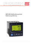
3.1 Supply voltage connection 5
The following controller versions are available:
AC versions
(KS92 only 230 V AC)
· 90...260 V AC
Frequency: 48...62 Hz
Power consumption: approx. 10 VA
24 V UC versions (only KS 94)
· 24 V AC , 48...62 Hz
The voltage limits are 24 V AC. (+10...-15 %)
· 24 V DC
With the 24 V DC version, the limits are within 19,2 and 30V.
3.2 Connecting the analog inputs INP
X1
Input INP1 1
Input for variable x1. (see page 31 ff)
a
Thermocouple
b
Resistance thermometer (PT100 in 3-wire connection)
c
Temperature difference as 2 w PT100 in 2-wire connection
d
Potentiometric transducer
e
Current
f
Voltage
X2
Input INP3 %
Dependent of configuration, this input is used for variable x2 or variable z.
The reference potential (GND) of this input is at terminal C10 (see page 34 ).
X3
Input INP4 %
Dependent of configuration, this input is used for variable x3, external set-point or override control (OVC).
The reference potential (GND) of this input is at terminal C10 (see page 34).
X2
Input INP5 3
This input is used for variable x2, for the external set-point or for external set-point
offset (configuration level C.180).
With voltage signals, A6 must be connected with the reference potential at A9 (see
page 34 )
4
5
6
7
8
9
A
+ mA
- mA
4
5
6
7
8
9
A
+ Volt
- Volt
Input INP6 2
This input is used for position feedback with 3-point stepping controllers, for the external set-point or for the
external set-point offset (configuration level C.180) (see page 35)
User manual KS92/94
14
12.07.2000
Electrical connections
3.3 Outputs OUT
Output OUT1 7
Dependent of version, OUT1 is a continuous, a logic or a relay output. It may be allocated to Y1 or to alarm.
With logic and continuous output, a protective earth must be connected to P13. The logic signal switches
between 0 and 20 mA (load ß 600 [) or 0 / > 12 V (load ? 600 [) (see page 34 ).
Outputs OUT2, OUT4 and OUT5 6
These outputs are relay outputs. Output OUT2 is configured either for y2 or for alarm (see page 38 ).
Outputs OUT4 and OUT5 are allocated to alarms LIM1 / LIM2.
With programmers, they can be configured in addition to outputs 1...4 or for program end (C.590 / C.591 )
(see page 38 ).
Output OUT3 &
Dependent of configuration, OUT3 is a continuous or a logic output. The logic signal switches between 0
and 20 mA (load ß 600 [) or 0 and 12 V (load ? 600 [).
Which signal shall be taken to this output must be determined at configuration level. Selection between
various controller outputs, process values and set-point is possible (see page 37 )
3.4 Digital inputs di
Digital inputs di1 and di2 4
Dependent of configuration (C.190 and C.191), inputs di1 and di2 can control the following procedures:
· Switch-over between internal set-point W (0) and externel set-point Wext (1)
· Switch-over between internal set-point W (0) and second set-point W2 (1)
· Switch-over between automatic (0) and manual (1) operation
· Set-point offset switch-on; normal (0) offset (1)
· Switch-over between normal correcting value (0) and safety correcting value (1)
· Controller switch-ON (0) or OFF (1)
· Switch-over between PI (0) and P (1); with 2/3-point and continuous controllers or
feedback switch-off with 3-point stepping controllers
· Bumpless switch-over between normal correcting value (0) and safe correcting value (1)
· Bumpless switch-over to internal set-point (tracking only di2) OFF (0) ON (1)
Digital inputs di3 to di12 90"§
di3
used for switch-over between local (0) and remote (1).
di4
used for switch-over between program STOP (0) and START (1) ( C.192; SPrSt).
di5
used for programmer RESET; normal (0), reset (1).
di6/di7
used for program number selection with programmer.
di6
di7
Programm
di7/di8
di10
di11
di12
12.07.2000
0
0
1
1
0
2
x
1
3
di8
di9
Parameter set
0
0
0
1
0
1
0
1
2
1
1
3
used for program number selection with programmer.
minimum delimitation of the correcting variable with 3-pnt.stepping controller
maximum delimitation of the correcting variable with 3-pnt.stepping controller and can be
configured for switching on the effective set-point offset ( C.190: SdWon).
switches over bumplessly to the internal set-point (tracking) OFF (0) ON (1).
and can be used for switching over to the second set-point W2 (C.190) OFF (0) ON (1).
15
User manual KS92/94
Electrical connections
3.5 Digital outputs do1 to do6 9
do1
do2
do3
do4
do5
indicates the status of control output 1 with programmer.
indicates the status of control output 2 with programmer.
indicates the status of control output 3 with programmer.
indicates the status of control output 4 with programmer.
indicates, if the controller is in manual or automatic mode, or
the Y1 condition with switching controllers (C.596).
indicates, if the controller uses the external or the internal set-point, or
status Y2 with switching controllers (C.597).
do6
3.6 Versions with integrated supply voltage
The supply voltage can be used only for energization of a 2-wire transmitter or for energization of max. 4
control inputs. The supply voltage is potential-free and can also be used for energizing inputs INP3 ... INP6
or for other units. Selection of supply
voltage or digital inputs is by S.I.L.
switches (see figure opposite).
Ü
Transmitter
supply voltage
Digital input
Ü
Position T
Position D
*
open
closed (D)
Ö
closed (T)
open
Ö
8.8.8.8
W2:ÀC
55%
Ü *
supply voltage is only applied to
a The
terminals A12 and A14 with INP1 configured for current or
thermocouple (C.200; type) and the S.I.L. switches set for
transmitter supply (factory setting)! With the S.I.L. switches set to
digital input, the voltage is applied to terminals A1 and A4
independent of the configuration of input INP1. In this case, the
voltage input of INP5 is not available.
Supply voltage for energization of
digital input (e.g. di1...di4)
+
di 1
di 2
1
di 3
di 4
2
3
4
Connection of a 2-wire transmitter
on example of INP1 or INP5
A
External use of the
supply voltage
B
(Option)
_
1
2
3
4
A
_
+
12
13
14
15
16
Ö
8.8.8.8
Y:ûûûûûî
A
*
_
UT
+
_
+
1
2
3
4
5
6
7
8
9
10
11
12
13
14
15
_
INP5
+
_
+
INP1
16
User manual KS92/94
16
12.07.2000
Electrical connections
3.7 Connecting the bus interface !
TTL or RS422 or RS485, PROFIBUS or INTERBUS. With TTL, an interface module for conversion to
RS422/RS485 is required. 4 units may be connected to an interface module.
3.7.1 Operation
KS94 data can be read, or displayed and modified from the front-panel PC interface or via the serial
interface.
After delivery of controller KS94, the PC interface is active. KS94 configuration and parameter setting are
supposed to be done by means of the engineering tool before commissioning.
Switch-over to the serial interface is either
· via operator dialogue (front):
·
press M ? during 3 sec. r Para flashes
pressI until CBus flashes r M confirm briefly.
press M ? during 3 sec. r Para flashes
press I until CFrnt flashes r M confirm briefly.
display
CBus
display
CFrnt
= switch over to rear interface
= switch over to front-panel interface
or by activating ‘REMOTE’ (r page 17). Switching back to LOCAL does not cause switch-over to the
front-panel interface.
Switch-over to the PC interface is only possible with the R/L input set to LOCAL.
3.7.2 Remote/local
Units with serial interface are fitted with a hardware input (di3) for switch-over between REMOTE and
LOCAL operation (R/L).
B
1
-
2
+
3
di3
During ‘REMOTE’all operations via the serial interface (writing and reading) are permissible. The
following operations are still possible via the keys of the local operating front panel:
q Display switch-over
q Display of parameters without modification
q Display of configuration data without modification
During remote operation, the PC interface cannot be operated. When switching over from LOCAL to
REMOTE, an active PC interface is switched off.
PROFIBUS interface
During ‘LOCAL’, only reading of all
data via the serial interface is permissible.
Modifications are not possible,
exception:
any data related only to the interface
or which are not adjustable local
via local operation.
12.07.2000
front-panel interface
front-panel operation
17
R/L input
User manual KS92/94
Electrical connections
3.7.3 Connection examples
Fig.: 1
TTL-interface connection
KS 92/94
1
2
3
4
5
6
1
2
3
4
5
6
7
7
8
8
9
9
10
11
10
12
11
12 13
14
13 15
14
15 16
Interface
module
1
2
2 3
3 4
4 5
5 6
6 7
7 8
8 9
9 10
10 11
11
11 12
12 13
12
13 14
13
14
14 15
15
15
16 16
1
max. 1m
12
GND
14
7
3
TRE
15
16
Fig.: 2
6
2
13
16
1
+5V
8
TXD
4
RXD
5
9
RS422-interface connection
1
2
3
4
5
6
7
8
9
10
11
12
1
2
3
4
5
6
7
8
9
10
11
12
13
14
15
Master
e.g. IQT150
1
2
2 3
3 4
4 5
5 6
6 7
7 8
8 9
9 10
10 11
11
11 12
12
12 13
13
13 14
14
14 15
15
15
16 16
1
13
14
15 16
max. 1000m
12
13
GND
14
RXD-A
15
16
GND
TXD-A
TXD-B
RXD-A
RXD-B
RXD-B
4
8
3
7
TXD-B
16
5
9
2
TXD-A
6
1
Fig.: 4
RS485-interface connection
Fig.: 3
PROFIBUS-DP connection
1
2
3
4
5
6
7
8
9
10
11
12
1
2
3
4
5
6
7
8
9
10
11
12
13
14
15
1
2
2 3
3 4
4 5
5 6
6 7
7 8
8 9
9 10
10 11
11
11 12
12 13
12
13 14
13
14
14 15
15
15
16 16
1
13
14
15 16
12
5
VP
13
14
9
max. 1200m
GND
4
8
RXD/TXD-N (A)
15
3
7
RXD/TXD-P (B)
2
16
6
16
1
Fig.: 5
I NTER B US connection
10
11
12
13
14
15 16
User manual KS92/94
1
11
2
3
4
5
6
7
8
9
10
11
12
13
14
15
16
22
33
44
55
66
77
88
99
IN
OUT
UL
BA
CC
6
RD
TR
7
IN
8
6
7
8
9
1
2
3
4
5
9
1
2
3
4
5
DO 6
DO 1
DI 7
DI 2
GND 3
Strain
relief
green
yellow
pink
grey
brown
1
2
3
4
5
6
7
8
9
D-SUB- 9-pole socket
7
8
9
1
2
3
4
5
6
7
8
9
10
11
12
13
14
15
D-SUB- 9-pole plug (male)
KS 94
1
2
3
4
5
6
OUT
receiving interface
18
DO
DO
DI
DI
GND
6
1
7
2
3
5
9
green
yellow
pink
grey
brown
linked
Strain
relief
sending interface
12.07.2000
Operation
4 Operation
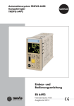
4.1 Front view
Fig.: 6
Front view
English
LED 2 e.g. Cooling
LED 1 e.g. Heating
Locking screw
LED 3 e.g. Alarm 1
LED 4 e.g. Alarm 2
Text 1 e.g. physical unit
Display 2 e.g. Set-point
Display 1 e.g. Process value
ÀC
Text 2 e.g. Bargraph /
Dialogue
Selection key
Increment key (z)
Decrement key (u)
PC interface
Manual/Automatic key
Locking screw: Locks the controller module in the housing.
LEDs:
indicate the status of controller outputs Y1, Y2 and alarms LIM1,
LIM2 (other settings at configuration level C.800).
Display 1:
indicates the process value at operating and parameter level,
and the configuration code at configuration level.
Display 2:
indicates the set-point during automatic operation at operating level and
the correcting value during manual operation. The values are adjustable directly
with push-buttons D and I. Further displays can be adjusted by means of
configuration code (C.801).
Text 1:
indicates the short-form dialogue or the unit of display 2.
Further displays can be adjusted by means of configuration code (C.800).
Text 2:
indicates the correcting variable bargraph. Further displays can be adjusted
by means of configuration code (C.800).
PC interface:
PC connection for configuration, parameter setting and operation by means of
the engineering tool
4.2 Status displays
FAIL
60 160
60
ÀC
Y:ûûûûûû____
This message signals a sensor error. Possible cause:
Break or wrong polarity with thermocouple
Break or short circuit with Pt100 and potentiometric transducer
Break with 4…20mA and 2...10V standard signal
The following messages can be displayed in KS92/94 ‘Text1’.
ClockF Faulty clock (real-time clock must be re-adjusted.)
12.07.2000
Recov
Recovery function is active (after power recovery, the process is controlled with the correcting variable
determined last.
Grw
Y2
AdaF
Ada
Timer
CalEr
Block
DirEr
YFail
Gradient function is active (the set-point changes at an adjustable (Grw+/-) rate of change).
The second correcting variable (safety correcting variable) is active
Self-tuning was canceled with error.
Self-tuning busy
Timer function is active (a future starting point was not reached yet).
Calibration error with automatic position feedback calibration.
No motor actuator reaction (only with the DAC function activated).
Faulty motor actuator output action (only with the DAC function activated).
Yp error (potentiometer defective or not connected (only with activated DAC function).
19
User manual KS92/94
Operation
4.3 Menus 1...3
Apart from the parameter and configuration words, the following dialogue words are used (Text1):
CBus
Clear
Clock
Conf
End
Exit
Hold
Mark
More
OStar
Para
PRun
PSet
Quit
Text1
CFrnt
OStop
PStop
PRes
Signification
PC communication via interface at terminals B12...B16
The additional display selected at operating level is deleted (r Mark)
Setting the clock
Transition to configuration level
Return to the previous selection menu
Return to operating level (main display)
The displayed parameter is determined as standard display.
The displayed parameter is stored as additional display at operating level (r Clear)
The configuration level area described with MORE is accessible
Self-tuning is started or stopped
Transition to parameter level
Programmer starting or stopping
Programmer preset or reset
Return to operating level (main display) without storage of the values changed last
4.4 The operating level
The operating level comprises main display Ü and extension *. During the main display, automatic or
manual operation can be selected (H). With automatic, the set-point, and with manual, the correcting value
can be adjusted directly (ID). In the extension, the number and sequence of displays is dependent of
selected functions. Max. 12 parameters from the parameter level can be displayed (Mark i Clear).
Some of these parameters are directly adjustable (ID). A parameter can be displayed continuously with the
Hold function. (PressM < 3s r Select parameter (press ID) r M > 3s r Select Hold (Press ID) r
M). The extension can be left with Exit and M or after a timeout of 60 s or with H. With H, the other
operating mode is also selected.
+ If the set-point is set to ‘----‘ by means of D, the controller is switched off!!
Menu 1 is always selectable at operating level: deletion of additional display (Clear), communication
interface switch-over (CBus i CFrnt) and starting (OStar) or stopping (OStop) the self-tuning,
setting the clock (Clock), operate the programmer (PRun i PStop; PRes; PSet) and transition to
parameter level (Para).eter level (Para).
Fig.: 7
Operation
60s
282.1
ÀC
282.0
Y:ûûûûûî
55%
282.0
-2.0
xw
Wp12.3 Run Loc
Regelabweichung
Y:ûûûûûî
Ü
User manual KS92/94
W
282.0
282.0
Exit
Sollwert
282.0
282.1
Man.
282.0
280.0
State
55
W
282.0
Sollwert
55%
>3s
Menue1
20
*
12.07.2000
Operation
4.5 Parameter and configuration level
Menu 1 is always selectable at operating level: several operations (r 7.2) and transition to parameter level
(Para).
Menu 2 is always selectable at parameter level: selection of additional displays (Mark), return to parameter
level (End), return to operating level (Exit), transition to configuration level (Conf).
Menu 3 is always selectable at configuration level: permitting the MORE area (More), return to
configuration level (End), return to operating level without storage of the last changes (Quit) or with
storage of the changes (Exit).
Fig.: 8
Parameter setting
281.8
W2:ÀC
End
Hold
Clear
Clock
CBus
PRun
PRes
PSet
OStar
Para
282.0
Y:ûûûûûî
55%
Para
End
Mark
Exit
Conf
Menu1
Conf
Menu2
15s
60s
End
More
Quit
Exit
15s
MORE
Menu3
15s
Value adjustment is as follows (parameter values / configuration codes):
Fig.: 9
Example for a
single parameter
Fig.: 10 Example for combined data
(e.g. C-Codes)
C.530
OUT2
250
LimH1
Signaloutput 2
5
C.530
Max.Lim.value.1
OUT2
C.530
End
02.0.1
Main Config
250
LimH1
5
Max.Lim.value.1
C.530
Src
02.0.1
Corr. value Y2
12.07.2000
21
C.530
Type
Relay
02.0.1
C.530
Mode
Normal
02.0.1
User manual KS92/94
Operation
User manual KS92/94
22
12.07.2000
KS92/94 function survey
5 KS92/94 function survey
5.1 Basic hardware functions
Various KS92/94 controller versions according to order number are available. Decisive for the hardware is
the number of connected circuit boards, i.e. connectors.
A large number of standard applications can be realized only with the KS92/94 basic version, which contains
circuit boards P and A. The input and output functions shown in the following correspond to the basic
setting. Finally, however, the individual configuration is decisive:
5.1.1 Circuit board P:
Output OUT1:
positioning signal
OUT1 can be ordered as a current or relay output.
Dependent of selected controller type, it can be operated as a
continuous 0/4...20mA signal or as a 0/20mA logic signal.
Output OUT2:
Output OUT4:
Output OUT5:
positioning signal
limit signal (alarm)
limit signal (alarm)
5.1.2 Circuit board A
Universal input INP1:
process variable x1 (process value)
Difference input INP5:
external set-point We
Measurement input INP6: Position feedback yp with 3-point stepping and continuous controller
Control input di1:
Control input di2:
set-point switch-over
automatic/manual switch-over
5.1.3 Circuit board B (optional)
Circuit board B contains a serial interface (TTL or RS485; ISO1745- and MODBUS protocol), a real-time
clock and additional control inputs and outputs, which are reserved exclusively for the programmer
functions:
Control input di3:
Control input di4:
Control input di5:
Control input di6:
Control input di7:
“remote/local” mode
programmer start/stop
programmer reset
program selection
program selection
Control output do1:
Control output do2:
Control output do3:
Control output do4:
control output 1
control output 2
control output 3
control output 4
5.1.4 Circuit board C (optional, only possible with KS94)
Circuit board C offers further configurable inputs and outputs.
Difference input INP3: disturbance variable z or process variable x2 (ratio, three-element, ...)
Difference input INP4: external set-point We, set-point offset dWe, override control OVC, process
variable x3 (three-element), ...
Current output OUT3: operating mode continuous 0/4...20mA or logic 0/20mA; function configurable
Control input di8:
Control input di9:
control input di10:
Control input di11:
Control input di12:
Control output do5:
Control output do5:
12.07.2000
selection control parameter set 1...4
selection control parameter set 1...4
override control OVC+ with three-point stepping controllers
override control OVC- or set-point correction dW(e) “On/off”
w/W2 switch-over
positioning signal y1 (switching controllers) or “A/M” status
positioning signal y2 (switching controllers) or “i/e” status
23
User manual KS92/94
KS92/94 function survey
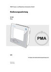
5.2 Survey of included function modules
A survey of function modules and their interdependence is shown below.
The individual function modules are described in the following sections.
Fig.: 11
Survey of functions
À
KS 9x
H D I M
serial interface
Operating and display
Func1
Func2
INP 6
Func1
Func2
di 1
di 2
C
INP 3
INP 4
C
di 8
di 9
di 10
di 11
di 12
Func1
Func2
Func1
Func2
W
We
Wp
W2
Set-point
connecting
Process value
processing
Ratio
Self
tuning
(D)PID - Controller
1
2
3
3 - element
mean value
Yp-signal
.
.
.
Corr. var. processing
di 4
di 6
OUT 1
Timer
B
di 5
P
Control and
monitoring
Controled
adaption
PROG
Disturbance
conditioning
OUTPUT
Self tuning
OUT 2
OUT 4
Signalprocessing ( Src)
INP 5
Set-pointprocessing
ALARM
OUT 5
C
Func
OUT 3
C
do 5
do 6
B
do 1
do 2
Output
limiting
Func2
Automatic/manual
Y / Y2, ect.
Func1
Auxiliary
variable z
INP 1
Signalprocessing ( Src)
A
CONTR / TUNE
Preprocessing
Limit value processing
INPUT
do 3
do 4
di 7
di 3
Remote / local - switch-over
(R/L)
User manual KS92/94
24
12.07.2000
KS92/94 function survey
5.3 Galvanic isolation
Galvanic isolation is necessary for safety (contact safety) and for measurement reasons.
Due to the KS92/94 electronics construction, galvanic isolation is standard without extra charge.
A transformer in the power supply always isolates all inputs and outputs from the supply voltage. Data
exchange between electronics p.c.b. A and power supply or output p.c.b. P is also galvanically isolated. I.e.
positioning output OUT1 which can be designed for 0/4...20 mA, is also isolated from all inputs.
Control inputs di, control outputs do and serial interface are always galvanically isolated via opto-couplers,
i.e. they cannot contribute to stray potential and error due to leakage current.
Although additional current inputs INP3 and INP4 of option C are galvanically connected (difference inputs;
COMMON), they are isolated from the rest of the instrument. This also applies to current output OUT3.
This means: if hardware option C is used, process value, set-point and correcting variable can be
galvanically isolated. Even an additional process value output OUT3 (0/4...20mA) is galvanically isolated
from the input.
Common control signals as A/M, w/W2, int/ext, etc., e.g. signals coming from a PLC and in many cases
without galvanic isolation, are handled with galvanic isolation and do not cause potential compensation. The
same applies to control outputs do, which are connected electrically with control units, i.e. which imply a
risk of potential connections.
In the connecting diagram on page 13, the double lines clearly show the galvanic isolations throughout the
controller.
Galvanic isolation of inputs and outputs is shown in the following drawing.
KS94
y4
OUT3
C
y2
Process value
OUT1
y
INP1
x
Process value
P
y1
Corr. value
We
Set-point
INP4
C
y3
y5
12.07.2000
25
User manual KS92/94
KS92/94 function survey
5.4 Input conditioning
Before the pre-filtered (time constant ...; limiting frequency ...) analog input signals are available as digitized
measurement values with physical unit and can be used e.g. as process value, set-point or position feedback,
they undergo extensive conditioning.
Function library
Öx
SQRT
SQRT
CHAR
SCAL
Amplifier
Sensor
Linearimonitoring zation
INP
Skaling
mA
X0
X100
Filter
LAG1
Mesurement
value
correction
Tfm
C214
0,5...9999s
Measurement value processing
f()
f()
FUNC 1
FUNC 2
Measurement
value
Signal pre-processing
5.4.1 Input circuit monitor
g
Thermocouples
The input circuit monitor provides thermocouple checking for break and wrong polarity. An error is found, if
the value of the measured thermovoltage is by more than 30 K below the span start.
Pt100 measurements and potentiometric transducers are monitored for break and short circuit.
Current and voltage signals
With current (0/4...20 mA) and voltage signals (0/2...10V), monitoring for exceeded range (I > 21,5 mA or U
> 10,75 V) and for short circuit (I < 2 mA or U < 1 V) with “life zero” signals is provided.
Sensor errors can be output as control signal. In case of error, upscale or downscale action of the input ciruits
are possible.
Moreover, a “substitute” value can be defined with controller KS94.
Unless the main correcting variable, but e.g. external set-point, set-point offset or external output limiting are
concerned, control can be continued also with failure of an auxiliary variable.
After removal of a sensor error, the controller waits, until the input signal has settled (approx.10s), before the
controller is initialized (outputs switched off during several seconds).
5.4.2 Scaling
Standard signals mA and V are scaled according to the physicl measuring range of the transformer (x0,
x100).
With potentiometric transducer measurements (INP1, INP6), “calibration” is according to a well-proven,
practice-oriented method. Bring the transducer to span start and then to span end position and “calibrate” it
for 0% or for 100% by pressing a key at parameter level. Calibration is basically a scaling procedure,
whereby gradient and zero correction are calculated automatically via the firmware.
5.4.3 Linearization
Generally, thermocouples and Pt100 are measured in the overall physical measuring range according to data
sheet, and linearized according to the relevant allocation table. Linearization is realized by error curve
approximation with up to 28 segment points.
User manual KS92/94
26
12.07.2000
KS92/94 function survey
5.4.4 Additional measurements
Dependent of configured sensor type, additional and corrective measurements are required.
The amplifier zero is checked with all measurement types and taken into account during measurement value
calculation. The lead resistances with Pt100 and potentiometric transducer, and the cold-junction reference
temperature (internal TC) with thermocouples are measured additionally.
5.4.5 Filter
In addition to filtering in the analog section of each input signal, a 1st order filter is adjustable (filter time
constant 0,5...9999s; configuration).
5.4.6 Scanning intervals
The internal scanning interval of controllers KS92 and KS94 is 100ms.
A survey of input and output scanning intervals, front LEDs, operating keys and serial interfaces is given in
the following table.
Description
Scanning interval
Serial interfaces
100 ms
LEDs
Keys
100 ms
100 ms
Circuit board
B,
front
front
front
INP1
TC, with thermocouples
Compensation measurement of the lead
resistance with Pt100 and transducer
Zero correction using an internal reference
voltage
200 ms
2,4 s
A
A
2,4 s
A
2,4 s
A
INP3
INP4
INP5
INP6
200 ms
200 ms
800 ms
400 ms
C
C
A
A
OUT 1,2,4,5
OUT3
100 ms
100 ms
P
C
di3...7
di8...12
do1...4
do5,6
100 ms
100 ms
100 ms
100 ms
B
C
B
C
5.4.7 Linearization error
Thermocouples and Pt100 are linearized within nearly the overall physical measuring range. Linearization is
with up to 28 segments, which are placed in the error curve optimally to compensate the linearity errors. As
the error curve approximation is only by polygons and not by an nth order polynomial, the remaining error is
zero in some points of the characteristic curve. Between these “zero points”, however, there is a very low,
though measurable remaining error. For reproducibility, however, this error is not relevant, because it would
be reproduced in exactly the same point, if the measurement would be repeated under identical conditions.
5.4.8 Temperature compensation
Measurement of the cold-junction reference temperature with thermocouples is using a PTC resistor. The
temperature error thus determined is converted into mV of the relevant thermocouple type, linearized and
added to the measurement value as correcting value with correct polarity. The remaining error with varying
cold-junction reference temperature is approx. 0,5K/10K, i.e. about one twentieth of the error which would
occur without compensation. Better results are possible with a controlled, external TC, which is adjustable
within -99...+100°C dependent of temperature adjusted at the cold-junction reference.
With comparative measurements for assessment of the “reproducibility”, however, constant environmental
conditions are indispensable when working with internal TC! A draft at the PTC resistor of the cold-junction
reference can be sufficient to produce a measurement error.
12.07.2000
27
User manual KS92/94
KS92/94 function survey
5.4.9 Measurement value correction (optional)
The measurement value correction can be used for correcting the measurement.
Prerequisite: Configuration word C.205; XKorr = 1 (r page 104)
In most case, the relative accuracy and reproducibility rather than the absolute one is of interest, e.g.
·
·
·
·
measurement error compensation in a working point (set-point control)
minimization of linerarity errors in a limited working range
(variable set-point)
conformity with other measuring equipment (recorders, indicators, PLCs, ...)
compensation of the sensor, transmitter, etc. stray errors
The optional measurement value correction can be designed both for zero correction and gain matching. It
corresponds to a scaling mx+b, with the difference that the controller firmware calculates the gain m and the
zero offset b from the pre-defined values for process value (x1in; x2in) and set-point (x1out; x2out) of two
reference points.
Example 1:
Zero offset
x1in = 100°C
x2in = 300°C
corrected
characteristic
x1out = 100°C + 1,5°C
x2out = 300°C + 1,5°C
X2out
X2in
The difference between corrected values and input
values is equal over the complete range.
input
characteristic
X1out
X1in
Example 2:
Gain change (rotated around the coordinate origin)
x1in = 0°C
x1out = 0°C
x2in = 300°C
x2out = 300°C + 1,5°C
corrected
characteristic
X2out
X2in
The corrected values are equal to the input values at
x1in and x1out, but the difference increases.
input
characteristic
X1out = X1in
Example 3:
corrected
characteristic
Zero and gain matching
x1in = 100°C
x2in = 300°C
x1out = 100°C - 2,0°C
x2out = 300°C + 1,5°C
X2out
The corrected values are already different at input values
x1in and x1out and the difference increases additionally.
X2in
input
characteristic
X1out
X1in
User manual KS92/94
28
12.07.2000
KS92/94 function survey
5.5 Signal pre-processing
Input value conditioning is followed by signal pre-processing.
The analog input signals can undergo further conditioning.
Func1 and Func2 are spacekeepers for configurable functions which can be selected from the following
function library:
Funktion library
Öx
SQRT
SQRT
CHAR
SCAL
Amplifier
Sensor
Linearimonitoring zation
INP
Scaling
mA
X0
X100
Filter
LAG1
Mesurement
value
correction
Tfm
C214
0,5...9999s
Measurement value processing
f()
f()
FUNC 1
FUNC 2
Measurement
value
Signal pre-processing
Each function can be used only once (either in Func1 or in Func2). The table gives a survey of inputs and
usable functions.
Function
SCAL
CHAR
SQRT
LAG1
12.07.2000
INP1
(C.220)
X
X
X
X
INP3
(C.320)
only with KS94
—
only with KS94
only with KS94
INP4
(C.370)
only with KS94
only with KS94
only with KS94
only with KS94
INP5
(C.420)
X
—
X
X
INP6
(C.470)
X
—
X
X
SCAL -
Scaling
Scaling is done according to equation
OUT = m w INP + b.
Hereby, parameters m and b can be adjusted so that
inverse characteristics can also be realized.
Adjustable parameters: m = gain and b = offset
CHAR -
Linearization
Y
Up to 8 adjustable segment points ys8
(value pairs xsi/ysi) can be used to
>
simulate or linearize non-linear
ys7
<
'
functions. The number of value pairs ys6
ys5
ä
is limited to 8 (7 segments). If less
than 8 value pairs are used, the first ys4
Ö
*
unused segment must be switched ys3
ys2
off by entry of the xs-value into
Ü
“——”. Offset and gradient for the ys1
relevant intervals are determined
X
automatically from the adjusted
xs2
xs3
xs4 xs5
xs6
xs7
xs8
xs1
value pairs. The segment points are
interconnected by straight lines, so
that there is a defined output value (ys) for each input value (xs). Beyond the defined intervals,
the first or last segment is prolonged. Adjustable parameters: for each input - (x1,y1),
(x2,y2)...(x8,y8)
Note that the input values (x-values) must be entered in ascending order.
29
User manual KS92/94
KS92/94 function survey
SQRT-
Square root
The square root of the input signal is calculated and
the result is multiplied by parameter “gain”.
OUT = gain * root INP
If the value under the root is negative, the result is set to 0.
Adjustable parameter: for each input - gain
- LAG1
Filter
The input value is taken to the output with
delay. The delay is according to a 1st order e-function
(1st order low pass) with the filter time adjustable
with parameter Tf.
Adjustable parameter: Tf = filter time
User manual KS92/94
30
12.07.2000
KS92/94 function survey
A
12
13
14
15
5.6 Inputs
0%
100%
16
The input names and numbers were selected for utmost language-independent, international clarity of the
inputs and outputs on the process value display (7 segments) during configuration.
Digital inputs and output are marked with lower case letters to permit clear distinction of “0" and ”o" on the
display.
INPUT: - analog inputs
The signal inputs for the previously selected controller configuration are determined in this main group. The
signal inputs for the selected controller function are displayed in the configuration menu. As with control
function configuration, a large number of applications can be covered by determination of the main
configuration. Special cases can be matched and adjusted by additional option configuration at the second
level. INP2 is not available with controllers KS92/42. Therefore, there is a gap in the input sequence. Max.
the following five signal inputs are available:
·
·
·
process value x:
external set-point We, dWe:
position feedback yp:
INP1, INP3 or INP4
INP5
INP6
5.6.1 Signal input 1 INP1 (main variable x1) (r C.200)
The analog input INP1 is used as main variable x1.
The input sensor type can be determined as thermocouple, resistance thermometer, potentiometric transducer
or as a standard signal. The physical unit is freely selectable. If required, additional input configurations can
be determined with the extra configuration.
A
12
13
14
15
16
q Thermocouple input
The following thermocouple types are configurable as standard:
Type E, J, K, L, N, R, S, T and W to IEC584.
The signal behaviour can be affected by configuration of the following points. Distinction of internal
and external temperature compensation is made (r C.205).
· Internal temperature compensation:
The compensating lead must be taken up to the controller terminals. Lead resistance adjustment is
not required.
· External temperature compensation:
A separate cold-junction reference with a fixed reference temperature must be used (configurable
between 0 and 100°C) (r C.210)
The compensating lead must be taken only up to the cold-junction reference, from which point
copper lead must be used. Lead resistance adjustment is not necessary.
· Upscale (set-point << process value) or downscale (set-point >> process value) action of the built-in
TC monitoring can be configured, or a fixed substitute value can be used for the action. (r C.205).
· For input value processing, a filter time constant with a numeric value between 0,5 and 999,9 is
adjustable (r C.214).
· A process value correction is configurable (r C.205).
The order of configuration is as follows:
C.200r C.205 - (C.210) - (C.214)
12.07.2000
31
User manual KS92/94
KS92/94 function survey
q Resistance thermometer input
Resistance thermometer, temperature difference
With a resistance thermometer, the signal behaviour with sensor break can be determined
(r C.205). Temperature compensation is not required and therefore switched off. With temperature
difference measurement, calibration by means of short-circuit is required.
Lead resistance adjustment can be done using e.g. the 10 calibrating resistor (order no. 9404 209
10101). Dependent of sensor type, the controller must be configured for one of the following inputs:
·
·
·
resistance thermometer Pt 100 with linearization
temperature difference with 2 x Pt 100 and linearization
linear potentiometric transducers
For input value processing, a filter time constant with a numeric value within 0,5 and 999,9 is adjustable
(r C.214). The decimal point (digits behind the decimal point) and process value correction can be
configured (r C.205).
Configuration is in the following order:
C.200 r C.205 - (C.214) - (C.215)
q Resistance thermometer Pt 100
The two ranges -99,9...+250,0 °C and -99,9...+850,0 °C are configurable (r C.205).
Connection is possible in two or three-wire circuit. Measuring leads must be of copper. The input circuit
monitor responds with -130°C (sensor break or lead break). The output action is configurable for:
·
·
·
A
upscale (set-point << process value) (r C.205)
downscale (set-point >> process value) (r C.205)
a fixed value (in case of error, the selected number is used for the value to be measured (r C.213).
q Resistance thermometer in 2-wire connection:
12
13
14
15
For lead resistance adjustment, disconnect the measuring leads
from the controller and short-circuit them in the connecting
head of the resistance thermometer. Now, measure the
resistance of the measuring lead using a resistance bridge and
connect a calibrating resistor (Ra) of the same value.
16
15
16
14
Ra = RL1+RL2
RL1
RL2
}
A
q Resistance thermometer in 3-wire connection:
12
13
14
15
The resistance of each input lead must not exceed 30 [. Lead
resistance adjustment is not necessary, provided that the
resistances Ra of the input leads are equal. If necessary, they
must be equalized using a calibrating resistor.
16
15
16
RL1
14
RL2
}
A
12
13
14
15
q Temperature difference 2 x Pt100
2
1
16
Range }1 - }2 is within -200,0...+300,0 °C (}2 = referene).
For lead resistance adjustment for INP1, take the controller into
manual operation and select calibrating parameter x0c as
shown in Fig.:12. Press the selector key to prepare the
calibration (“c” in the display x0c flashes). Now, short circuit
the input leads at the two PT100 resistors. Press the selector key
again to store the measured resistance value as lead resistance,
in order to correct the subsequent measurements accordingly.
Remove the short circuits of the leads.
User manual KS92/94
32
15
16
14
xeff =}1 - }2
RL1
}1
}2
RL2
12.07.2000
KS92/94 function survey
q Potentiometric transducer
The overall resistance ß 500 [ incl. 2 w RL.
Calibration or scaling are done with the sensor connected.
An input circuit monitor can be configured for sensor or lead break or short circuit. The action, process
value correction and decimal point are adjustable
(r C.205 and C.213).
Configuration is in the following order:
C.200r C.205 - C.211 - C.212 - C.214
Calibration for X0 and X100 is at parameter level as follows.
Calibration is only possible with the controller set to manual mode.
Potentiometric transducer calibration for X0 or X100 is possible via the interface and the front foil.
Calibration is in two steps:
Fig.: 12 Selecting parameter x0c / x100c
270
10.5
Man.
xw____áûô___ 12%
I
D
+ >3s
M
I
D
End
Hold
OStar
Para
M
+
A
12
13
14
15
I
D
M
+
End
Cal
M
I
D
End
X100c
X0c
I
D
End
X100c
X0c
+
I
D
End
INP6
INP1
M
+
M
X0c
c
+
·
Calibration for X0:
Select x0c as shown in Fig.: 12. Press the selector key, the “c” on the display x0c starts blinking.
Now, bring the potentiometric transducer into the position for X0 (usually lower end position). The
instantaneously valid value for INP1 appears on display 1. Press the selector key again to store this
actual value as X0.
·
Calibration for X100 must be done accordingly.
Select x100c. Press the selector key. The “c” of the display x100c starts blinking. Now, bring
the transducer into the position for X100 (usually upper end position). The instantaneously valid
value for INP1 is shown on display 1. Press the selector key again to store this actual value as X100.
q Standard 0/4...20 mA signal input
+
mA
_
16
A
12
13
14
15
End
Signl
Aux
Input
Contr
Tune
Limit
Setpt
+
Volt
_
16
12.07.2000
The input resistance is 50 [
During configuration, distinction of 0...20 mA and 4...20 mA is made. For the 4 ... 20 mA standard
signal, the behaviour with sensor break can be determined (C.213). M<%-2>oreover, the decimal point
and thus the digits behind the decimal point are configurable (r C.200). Additionally, a physical input
signal scaling by means of X0 and X100 is possible (r C.201 and C.202). For input value processing, a
filter time constant with a numeric value within 0,5 and 999,9 is adjustable (r C.214)
For configuration, proceed in the following order:
C.200r C.201 - C.202 - C.205 - C.213 - C.214
q 0/2...10 V input
The input resistance is ? 100 k[
During configuration, distinction of 0...10 V and 2...10 V is made. For the 2 ... 10 V standard signal, the
output action with sensor break can be determined (C.213). Moreover, the decimal point and thus the
digits behind the decimal point are adjustable (r C.200). Additionally, a physical input signal scaling
by means of X0 and X100 is possible (r C.201 and C.202). For input value processing, a filter time
constant with a numeric value within 0,5 and 999,9 can be used (r C.214).
For configuration, proceed in the following order:
C.200r C.201 - C.202 - C.205 - C.213 - (C.214)
33
User manual KS92/94
KS92/94 function survey
5.6.2 Additional signal input 3 / INP3 (optional) (rC.300)
This signal input is only available with option p.c.b “C” fitted.
It may be configured for ratio variable x2 or disturbance variable z (r C.105 or C.180).
Selection of standard input signals 0...20 mA and 4...20 mA is possible. The physical unit can be configured.
The input resistance is 50 [. For the 4...20 mA standard signal, the output action with sensor break can be
configured (r C.305 and C.313).
Physical input scaling is possible by determination of 0 % and 100 % (rC.301 and C.302). Moreover, the
decimal point, i.e. the digits behind the decimal point can be configured (r C.300).
For input value processing, a filter time constant with a numeric value within 0,5 and 999,9 is adjustable (r
C.314)
For configuration, proceed in the following order:
C.300r C.301 - C.302 - C.305 - C.313 - ( C.313)
5.6.3 Additional signal input 4 / INP4 (optional) (r C.350)
This signal input is only available with option p.c.b. “C” fitted.
It can be configured for three-element control x3, external set-point or external set-point offset (r C.180).
Selection of 0...20 mA and 4...20 mA standard input signals is possible. The physical unit can be configured.
The input resistance is 50 [. For the 4...20 mA standard signal, the output action with sensor break can be
determined(r C.355 and C.363).
A physical input scaling is possible by determination of 0 % and 100 % (rC.351 and C.352). Moreover,
the decimal point, i.e. the digits behind the decimal point can be configured (r C.350).
For input value processing, a filter time constant with a numeric value within 0,5 and 999,9 can be adjusted
(r C.364).
For configuration, proceed in the following order:
C.350r C.351 - C.352 - C.355 - C.363 - (C.364)
5.6.4 Signal input 5 / INP5 (ratio variable x2, ext. set-point Wext) (r C.400)
Analog input INP5 is used for connection of the signal for ratio variable x2 or for the external set-point
Wext, if option p.c.b. is not fitted in the controller and with the function selected during controller
configuration. Selection of 0/4...20 mA and 0/2...10 V signals is possible. The physical unit can be
configured.
+ This input is a difference input. Terminal A9 is used as reference potential (Common). With voltage signals,
terminal A6 must always be connected with terminal A9.
The input resistance is 50 [ as mA input and ? 100 k[ as V input.
For the 2 ... 10 V or 4...20 mA standard signals, the output action with sensor break can be determined (r
C.405 and C.413). Moreover, the decimal point, i.e. the digits behind the decimal point can be selected
(C.400). Additionally, a physical input scaling by determination of 0 % and 100 % is possible (r C.401
and C.402).
For input value processing, a filter time constant with a numeric value within 0,5 and 999,9 can be adjusted
(r C.414)
Configuration is in the following order:
C.400r C.401 - C.402 - C.405- C.413 - (C.414)
See also external set-point Wext page 45 and ratio controller page 49
User manual KS92/94
34
12.07.2000
KS92/94 function survey
5.6.5 Signal input 6 / INP6 (auxiliary variable yp, position feedback yp) (r C.450 )
The signal for auxiliary variable yp or position feedback is configured at analog input INP6, if this was
selected during controller configuration.
For this input, the decimal point and thus the digits behind the decimal point can be selected (r C.450)
Moreover, a physical input signal scaling by determination of 0% and 100 % is possible (r C.451 and
C.452).
The output action with sensor break can be selected only with 4...20 mA standard signal (r C.455 and
C.463).
For input value processing, a filter time constant with a numeric value within 0,5 and 999,9 can be adjusted
(r C.464).
Configuration is in the following order:
C.450r C.451 - C.452 - C.455 - C.463 - C.464
See also position feedback yP page 56
5.6.6 Digital inputs “di”
Energization of digital inputs “di” via an external 24 V DC supply is required. The current consumption for
each input is 5 mA.
The digital inputs can be energized by one or several voltage sources
(e.g. 24V PLC control outputs). Note that the negative potentials of the voltage sources are identical and
must be taken to the corresponding controller connecting terminals.
Connecting examples:
B
A
1
2
(+) Imax. 5 mA di 1 3
Imax. 5 mA di 2
( -)
(+) Imax. 5 mA
Imax. 5 mA
Imax. 5 mA
Imax. 5 mA
Imax. 5 mA
di 3
di 4
di 5
di 6
di 7
24V (ext.)
Digital inputs
(connector A)
2
3
4
5
6
7
8
9
10
11
RL
Imax. 0,1 A
Imax. 0,1 A
Imax. 0,1 A
Imax. 0,1 A
24V (ext.1)
B
1
(-)
do 1
do 2
do 3
do 4
Digital inputs and outputs at one voltage
source (connector B)
24V
(ext.1)
(+) Imax. 5 mA
Imax. 5 mA
Imax. 5 mA
Imax. 5 mA
Imax. 5 mA
di 3
di 4
di 5
di 6
di 7
2
3
4
5
6
7
8
9
10
11
(-)
24V
(ext.2)
RL
(+)
Imax. 0,1 A
Imax. 0,1 A
Imax. 0,1 A
Imax. 0,1 A
1
( -)
do 1
do 2
do 3
do 4
Digital input and outputs at two voltage
sources (connector B)
Digital inputs di1 and di2
Dependent of configuration (C.190 and C.191), digital inputs d1 and d2 can control the following
operations. Allocating several functions to a digital input is also possible.
· Switch-over between internal set-point W (0) and second set-point W2 (1)
· Switch-over between automatic (0) and manual (1) mode
· Set-point offset switch-on; normal (0) offset (1)
· Switch-over between normal correcting value (0) and safe correcting value (1)
· Switches the controller ON (0) or OFF (1)
· Switch-over between PI (0) and P (1) with 2/3-point and continuous controllers or
feedback switch-off with 3-point stepping controllers
· Bumpless switch-over between normal correcting value (0) and safe correcting value (1)
· Bumpless switch-over to the internal set-point (tracking only di2) OFF (0) ON (1)
12.07.2000
35
User manual KS92/94
KS92/94 function survey
Digital inputs di3 to di12
di3
used for switch-over between local (0) and remote (1).
di4
used for switch-over between program STOP (0) and START (1) ( C.192; SPrSt).
di5
used for programmer RESET; normal (0), reset (1).
di6/di7
used for program number selection with programmer.
di6
di7
Program
di7/di8
di10
di11
di12
0
0
1
1
0
2
x
1
3
di8
di9
Parameter set
0
0
0
1
0
1
0
1
2
1
1
3
used for program number selection with programmer.
minimum delimitation of the correcting variable with 3-pnt.stepping controller
maximum delimitation of the correcting variable with 3-pnt.stepping controller and can be
configured for switching on the effective set-point offset ( C.190: SdWon).
switches over bumplessly to the internal set-point (tracking) OFF (0) ON (1).
and can be used for switching over to the second set-point W2 (C.190) OFF (0) ON (1).
5.7 Outputs
The input names and numbers were selected for utmost language-independent, international clarity of the
inputs and outputs on the process value display (7 segments) during configuration.
Digital inputs and output are marked with lower case letters to permit clear distinction of “0" and ”o" on the
display.
OUT: outputs
Dependent of hardware, there may be four switching outputs or three switching and one analog output.
Additionally, there may be optional output OUT3, which is located on plug-in options p.c.b. “C”.
OUT1 can be ordered as switching or continuous output. Outputs OUT2, OUT4 and OUT5 are always
switching and output OUT3 is always analog.
g
Behaviour of outputs with initialisation
All outputs are switched off for 100 ms at the end of initialisation. Analog outputs take over the lower output
value (0/4 mA) .
5.7.1 Signal output 1 OUT1 (r C.500)
Signal output OUT1 is used for controller correcting variable Y1/Y2. As it is a universal output, extensive
functions can be configured.
Which signal shall be taken to this output must be determined at configuration word C.500; Src :
w
w
w
w
w
00: none (output switched off)
01: controller output Y1/Yout1
02: controller output Y2/Yout2
03: controller output Ypid
04: position feedback Yp
w
w
w
w
w
05: control deviation xw
10: process value xeff
11: process value x1
12: process value x2
13: process value x3
w
w
w
w
w
20: Wint
21: Wext
22: dWext
23: Weff
24: Wp (programmer)
w
w
w
w
25: Alarm 1 (Limit 1)
26: Alarm 2 (Limit 2)
27: Alarm 3 (Limit 3)
28: Alarm 4 (Limit 4)
With a controller with continuous output, the output signal type can also be determined. 0...20 mA, 4...20
mA or logic signal 0 and 20 mA can be selected.
Direct or inverse motor actuator output action can be adjusted.
5.7.2 Signal output 2 OUT2 (r C.530)
Switching signal output OUT2 is used for controller correcting variable Y1/Y2. This is a relay output.
Which signal should be taken to this output must be determined at configuration level. Selection of
controller output Y1/2 and alarm signals (limit) is possible.
Direct or inverse motor actuator output action.
User manual KS92/94
36
12.07.2000
KS92/94 function survey
5.7.3 Additional signal output 3 OUT3 (optional) (r C.560)
This output is only provided in conjunction with options p.c.b. “C”.
Analog signal output OUT3 is used for a selectable controller signal. As this is a universal output, it can be
configured for extensive functions.
Which signal shall be taken to this output must be determined at configuration level ( C.560). Selection
between various controller outputs, process values and set-points is possible. Direct or inverse motor
actuator action is selectable. The output signal type can be determined. Selectable are 0...20 mA, 4...20 mA
or logic signal 0 and 20 mA.
Before the signals reach output OUT3, they can be processed again by means of function block “Func” (r
C.565). Configuration parameter Func permits selection of direct signal output, scaling and linearization.
direct signal output, the subsequently adjustable parameters X
a With
(C.570 and C.571)
0
and X100 are not taken into account
q Scaling
Scaling is adjustable according to reference values X0
and X100.
Example 1:
This scaling is a simple allocation of 0...100
to 0...20 mA.
The output is determined for 0...20 mA.
X0 = 0
X100 = 100
When applying value 50, the output is 10 mA.
20 mA
15 mA
10 mA
5 mA
0 mA
0
X0
25
50
75
100
X100
50
100
150
200
X100
85
110
X100
20 mA
Example 2:
This scaling is an allocation of 0...200
to 0...20 mA.
The output is determined for 0...20 mA.
X0 = 0 X100 = 200
When applying value 50, the output is 5 mA.
15 mA
10 mA
5 mA
0 mA
0
X0
Example 3:
This scaling is an allocation of 10...110
to 0...20 mA, whereby an offset is provided.
The output is determined for 0...20 mA.
X0 = 10
X100 = 110
When applying value 50, the output is 8 mA.
q CHAR - Linearization
20 mA
15 mA
10 mA
8 mA
5 mA
0 mA
10
X0
35
50
60
8 adjustable segment points
(value pairs xsi/ysi) can be used for simulation Y
ys8
or linearization of non-linear functions.
The number of value pairs is limited to 8 (7
ys7
segments). When using less than 8 value pairs, ys6
ys5
the first unused segment must be switched off
ä
ys4
by entry of the xs value into“----”.
Ö
ys3
Offset and gradient for the relevant intervals
*
ys2
are calculated automatically from the
Ü
adjusted value pairs.
ys1
The segment points are interconnected by
straight lines so that each input value (xs)
xs1
xs2
xs3
xs4 xs5
corresponds to a defined output value (ys).
Beyond the defined segments the first or the
last segment is prolonged. Adjustable parameters: (x1,y1), (x2,y2)...(x8,y8)
>
<
'
X
xs6
xs7
xs8
a Input values (x-values) have to be set in ascending order.
12.07.2000
37
User manual KS92/94
KS92/94 function survey
5.7.4 Signal output 4 OUT4 (r C.590)
Switching signal output OUT4 can be used for various signals. This is a relay output.
Which signal shall be taken to this output must be determined at configuration level. Selection of controller
output Y1/2 and alarm signals (limit) is possible. One of the four programmer outputs 1...4 and programmer
end is possible.
Direct or inverse motor actuator output action can be adjusted.
5.7.5 Signal output 5 OUT5 (r C.591)
Switching signal output OUT5 can be used for various signals. This is a relay output.
Which signal shall be taken to this output must be determined at configuration level. Selection of controller
output Y1/2 and alarm signals (limit) is possible. One of the four programmer outputs 1...4 and programmer
end is possible.
Direct or inverse motor actuator output action can be adjusted.
5.7.6 Digital outputs do1 to do6
do1
do2
do3
do4
do5
indicates the status of control output 1 with programmer.
indicates the status of control output 2 with programmer.
indicates the status of control output 3 with programmer.
indicates the status of control output 4 with programmer.
indicates, if the controller is in manual or automatic mode, or
the y1 condition with switching controllers (C.596).
indicates, if the controller uses the external or the internal set-point, or
status y2 with switching controllers (C.597).
do6
5.7.7 Input and output survey
q allocation of analog inputs / outputs and circuit boards
process inputs
INP1
INP3
INP4
INP5
INP6
A
f
circuit board
C (option)
process outputs
f
f
f
f
OUT1
OUT2
OUT3
OUT4
OUT5
f
f
P
circuit board
C (option)
f
f
f
q allocation of digital inputs / outputs and circuit boards
control inputs
di1
di2
di3
di4
di5
di6
di7
di8
di9
di10
di11
di12
User manual KS92/94
A
f
f
circuit board
B (option)
C (option)
f
f
f
f
f
control outputs
do1
do2
do3
do4
do5
do6
circuit board
B (option)
C (option)
f
f
f
f
f
f
f
f
f
f
f
38
12.07.2000
KS92/94 function survey
q Function allocation of analog inputs
X1
INP1
INP3
INP4
INP5
INP6
f
X2 X3
f
f
f
Ext.
Ext. set-point
set-point
offset
f
f
f
Auxiliary
variable z
Position
feedback
OVC
f
f
f
f
f
Min/Max
selection
f
f
f
f
q Function allocation of control inputs
Functions
Wint / Wext
Tracking on / off
{W on / off
w / W2
Auto / Man
PI / P
Y / Y2
Controller on / off
Programmer Run / Stop
Programmer Reset
Selection of programs
Remote / Local
Parameterset
OVC+ (Three-point stepping
controller)
OVC- (Three-point stepping
controller)
disabling 1)
OVC off/on
di1
di2
f
di3
f
f
f
f
f
f
f
f
f
f
f
f
f
f
di4
di5
di6
di7
di8
di9
di10 di11 di12
f
f
f
f
f
f
f
f
f
f
f
f
f
f
f
q Function allocation of outputs
Functions
Controller output 1
Controller output2
Alarm 1
Alarm 2
Alarm 3
Alarm 4
Process values (x1, x2, x3, xeff)
Set-points (w, weff, wext, dwext, wp
Control deviation (xw)
Correcting variable Ypid
Position feedback (Yp)
Contr. outputs 1
Contr. outputs 2
Contr. outputs 3
Contr. outputs 4
Program end
Status auto/man
Status Wint/Wext
OUT1
f
f
f
f
f
f
f
f
f
f
f
OUT2
f
f
f
f
f
f
OUT3
f
f
f
f
f
f
f
OUT4
f
f
f
f
f
f
f
f
f
f
f
OUT5 do1 do2 do3 do4 do5 do6
f
f
f
f
f
f
f
f
f
f
f
f
f
f
f
f
f
f
f
1) auto/manual key disabling, set-point adjustment, controller switch-off, value adjustment and
programmable controller operation.
12.07.2000
39
Handbuch KS92/94
KS92/94 function survey
User manual KS92/94
40
12.07.2000
Set-point functions
6 Set-point functions
6.1 Terminology
w
we
wp
W2
weff
SWi/e
Sw/W2
SWdon
S Wd
Wd
SWext
WTrac
STrac
WSel
internal set-point
external set-point
programmer set-point
second (internal) set-point
effective set-point
signal source for “internal/external” set-point switch-over
signal source for “weff / W2" set-point switch-over
set-point offset switch-on
signal source for set-point offset
set-point offset type
signal source for external set-point
tracking function switch-on
signal source for tracking
automatically selected lowest or highest set-point
C.190
C.190
C.190
C.180
C.106
C.180
C.106
C.190
C.106
6.2 General
The following set-point functions are selectable during configuration C.100 using parameter WFunc.
g
In addition to the described effective set-points, switching over to the second set-point W2 is possible.
Switch-over is via signal source Sw/W2 determined in configuration parameter C.190.
w
q Set-point (WFunc = 0)
With set-point control, the set-point is determined by
internal set-point W.
W2
w/W2
x
q Set-point/cascade (WFunc = 1)
With set-point/cascade control, switching over between internal
set-point W and external set-point We is possible. Switching over is
done via signal source SWi/e determined in configuration parameter
C.190.
we
Weff
-
INP 1
+
w
INP 5/6/4
e/i
W2
w/W2
x
Weff
-
INP 1
x-w
+
q Programmer (WFunc = 2)
w
With programmer control, the set-point is determined by the internal
programmer Wp. Switching over to the internal set-point W is
possible and must be done via the signal source SWi/e determined in
configuration parameter C.190.
q Set-point with external offset (WFunc = 3)
With set-point control with external offset, the effective set-point is
determined by internal set-point W, however, it can be affected by
external offset dW. The type of offset (additive or factor) is
determined during configuration C.106 by parameter dW.
The offset is switched on via signal source SWdon determined in
configuration parameter C.190.
12.07.2000
x-w
41
e/i
W2
w/W2
x
Weff
-
INP 1
+
dWon
dw
x-w
w
INP 5/6/4
+/*
W2
w/W2
x
Weff
-
INP 1
+
x-w
User manual KS92/94
Set-point functions
q Set-point/cascade with internal offset (WFunc = 4)
w
INP 5/6/4
we
+/*
With set-point/cascade control with internal offset, switching over
between internal set-point W and external set-point We is possible.
W2
dWon
Switching over is done via signal source SWi/e determined in
dw
Weff
configuration parameter C.190.
INP 1
x
External set-point We can be affected by an internal offset dW. The
+
offset type (additive or factor) is determined during configuration
C.106 by parameter dW. The offset is switched on via signal source SWdon determined in
configuration parameter C.190.
q Set-point/cascade with external offset (WFunc = 5)
we
INP 5/6/4
e/i
w/W2
x-w
w
+/*
Set-point/cascade with external offset permits switch-over between
W2
dWon
internal set-point W and external set-point We. Switch-over is via
INP 5/6
signal source SWi/e determined in configuration parameter C.190. dwe
Weff
External set-point We can be affected by an external offset dWe. The x INP 1
+
offset type (additive or factor) is determined during configuration
C.106 by parameter dW. The offset is switched on via signal source SWdon determined in
configuration parameter C.190.
e/i
w/W2
x-w
w
q Programmer with internal offset (WFunc = 6)
+/*
e/i
W2
With program control with internal offset, the set-point is determined
dWon
w/W2
by internal programmer Wp.
dw
Weff
The programmer value can be affected by an internal offset dW. The
INP 1
x-w
x
set-point offset type (additive or factor) is determined during
+
configuration C.106 by parameter dW. The offset is switched on via
signal source SWdon determined in configuration parameter C.190. The resulting set-point or internal
set-point W can be selected. Switching over is done via signal source SWi/e determined in
configuration parameter C.190.
w
q Programmer with external offset (WFunc = 7)
+/*
e/i
With program control with external offset, the set-point is determined
w/W2
INP 5/6
by internal programmer Wp.
dwe
Weff
The programmer value can be affected by an external offset dW. The
INP 1
x-w
x
+
type of set-point offset (additive or factor) is determined during
configuration C.106 by parameter dW. The offset is switched on via signal source SWdon determined
in configuration parameter C.190. This set-point can also be affected by an external offset dWe.
Switching over between the resulting set-point and internal set-point W is also possible and must be
done via signal source SWi/e determined in configuration parameterC.190.
dWon
User manual KS92/94
42
W2
12.07.2000
Set-point functions
6.3 Detailed set-point function block diagrams
The following set-point function block diagrams illustrate the interactions of configuration parameters and
possible control operations.
Fig.: 13 Set-point control C. 1 00; WFunc = 0
C.190
W100
C.106
Wsel
Grw+/-
0
1
di1
di2
di12
Timer
0
w
MAX
INP3
Sw/W2
WSel
MIN
1
W0
2
0
1
2
3
4
5
Grw2
0
1
W2
x
Weff
wÄW2
Fig.: 14 Setpoint / cascade control or programmer C. 1 00; WFunc = 1 or 2
C.190
C.190
eÄi
STrac
0
1
2
3
0
1
di2
di12
0
1
di1
di2
Sw/W2
Operation
0
1
2
3
&
C.106
WTrac
0
1
di1
di2
di12
Timer
?1
0
Weff
X
Wi
C.106
1
Wi
0
1
2
3
MAX
C.100
MIN
WFunc
We
1
Grw+/-
W100
0
1
S we
0
1
2
3
4
5
Wsel
0
C.180
0
INP5
INP6
INP4
C.190
SWi/e
0
1
1
2
Weff
x
W0
w
Grw2
2
Wp
INP3
W2
12.07.2000
WSel
x
43
wÄW2
User manual KS92/94
Set-point functions
Fig.: 15 Set-point control with external offset C. 1 00; WFunc = 3
C.190
C.190
dWon Ä off
STrac
0
1
2
3
0
1
di2
di12
Sw/W2
0
1
2
3
4
0
1
di1
di2
di11
&
C.106
WTrac
C.190
SWdon
0
Weff
X
Wi
C.106
1
W
0
1
C.106
*
MAX
0
+
0
1
2
3
0
INP5
INP6
INP4
W d
W+dWe
S dw
Grw+/-
W100
Wsel
0
C.180
0
1
2
3
4
5
0
1
di1
di2
di12
Timer
MIN
1
0
1
1
2
Weff
x
W0
w
W w dWe
Grw2
WSel
INP3
W2
x
wÄW2
Fig.: 16 Setpoint / cascade control with offset C.100; WFunc=4/5
C.190
C.190
eÄi
STrac
0
1
2
3
0
1
di2
di12
0
1
di1
di2
0
1
di1
di2
di12
Timer
?1
0
Weff
X
Wi
C.106
1
Wi
0
C.190
SdWon
S we
We
C.180
0
1
di1
di2
di11
0
MIN
S dw
INP3
W2
User manual KS92/94
0
1
1
2
Weff
x
W0
w
0
C.106
0
1
2
3
MAX
0
1
2
3
4
Grw+/-
W100
Wp+Wd
0
1
2
3
0
1
2
3
4
5
Wsel
1
C.180
0
INP5
INP6
INP4
Sw/W2
Operation
0
1
2
3
&
C.106
WTrac
0
INP5
INP6
INP4
C.190
SWi/e
W d
C.100
WFunc
dWe
5
dW
4
1
0
+
*
Grw2
1
WSel
x
44
wÄW2
12.07.2000
Set-point functions
Fig.: 17 Programmer with ext. or int. offset C. 1 00; WFunc = 6/7
C.190
eÄi
pÄi
STrac
C.190
0
1
2
3
0
1
di2
di12
C.190
SWi/e
0
1
di1
di2
0
1
2
3
&
C.106
WTrac
0
1
di1
di2
di12
Timer
?1
0
Weff
X
Wi
C.106
1
Wi
C.180
0
1
2
3
4
MIN
S dw
1
1
2
Weff
x
W0
w
0
C.106
0
1
2
3
MAX
0
Wp+Wd
0
1
di1
di2
di11
Wp
Grw+/-
W100
0
1
SdWon
0
1
2
3
4
5
Wsel
0
C.190
0
INP5
INP6
INP4
Sw/W2
Operation
W d
C.100
WFunc
dWe
7
dW
6
INP3
W2
1
0
+
*
Grw2
1
WSel
x
wÄW2
6.4 Safe set-point W2
Second set-point W2 can always be activated with highest priority.
In the past, W2 was called “safe set-point”. Whether W2 can have safety functions, or whether it is only a
pre-defined start position in defined process conditions is determined only by the way it is used and
integrated into an automation concept.
Dependent of configuration, switch-over to set-point W2 is possible via interface, front operation, timer or
one of control inputs di1,di2 or di12 (rC.190).
g
Second set-point W2 is handled with priority. If W2 was selected anywhere (front panel, interface or the
relevant control input), switching over at another facility is not possible.
6.5 External set-point Wext
Dependent of configuration, switching over between internal and external set-point via interface, front panel
operation or one of control inputs di1 or di2 is possible (rC.190). For making the external set-point
effective, a 1 signal (24 V) must be connected on the int/ext contact. For activating the internal set-point, a 0
signal (0V) must be applied to the int/ext contact.
Analog input “Wext” is connected to INP5, however, it can be configured also for INP4 (galvanically
isolated) or INP6 (yP input)(rC.180), if necessary. Signal pre-processing (Func1, Func2) permits
adjustment of the required set-point or correction characteristic as a function of the input signal.
(dependent of configuration: rINP5 C.370, INP4 C.420 or INP6 C.470).
g
12.07.2000
Internal set-point W has priority. If the internal set-point was selected anywhere (front panel, interface or the
relevant control input), switching over to external set-point We at another facility is not possible.
45
Handbuch KS92/94
Set-point functions
6.6 Set-point offset
The Set-point offset (internal dW or external dWe) can be added to the effective set-point or multiplied by it
(r C.106; dW). Examples for an additive set-point offset are “reduced stand-by set-point” and “outside
temperature-dependent supply temperature control”. Set-point offset as a factor can be used e.g. for split load
or O2 correction.
Dependent of configuration, the set-point offset can be triggered via interface, front panel operation, or via
one of control inputs di1,di2 or di11(r C.190; SdWon). For activating the set-point offset, a 1 signal (24 V)
must be connected to the relevant contact.
For de-activating the set-point offset, a 0 signal (0V) must be applied to the contact.
Analog input “S Wd” is connected to INP5, however, it can be configured also for INP4 (galvanically
isolated) or INP6 (yP input) (r C.180; SdW), if necessary. Signal pre-processing (Func1, Func2) permits
adjustment of the required set-point or correction characteristic as function of the input signal.
(dependent of configuration: r INP5 C.370, INP4 C.420 or INP6 C.470)
g
“Offset activated” has priority. With selection “offset active” at anywhere (front panel, interface or the
relevant control input), switching over at another facility is not possible.
6.7 Bumplessness
6.7.1 Set-point change
Set-point change in both direction is always bumpless. The effective set-point Weff approaches the modified
set-point (target) linearly, whereby gradients Grw+ and Grw- adjustable at parameter level determine the
slope. The gradient function is also active with programmer, however, it is not effective as long as the
program profile causes slower set-point changes than the adjusted gradients. Hereby, the gradient setting can
be used as safety function with incorrectly adjusted programmer.
For second set-point W2, an independent gradient Grw2 which is valid for the two switch-over directions
was introduced.
The gradient function is switched off with Grw+ and Grw- or Grw2 set to “----”.
Fig.: 18 Ramp function with set-point change
x,
w
we
w2
wp
Set-points, process value
upper set-point limit W100
Set-point 1
effective set-point
Grw+
Process value
Grw-
Set-point 2
lower set-point limit W0
Time
Change
Set-point 1 r Set-point 2
User manual KS92/94
46
Change
Set-point 2 r Set-point 1
12.07.2000
Set-point functions
6.7.2 Set-point switch-over (w/w2, Wext/Wint, w/wp, Controller ‘On’)
g
Control with the new set-point starts linearly from the instantaneous process value. The slope of the ramp is
determined dependent of direction by Grw+, Grw- or Grw2. This is also valid, if the process value at
switch-over time is out of the adjustable set-point range W0/W100 (e.g. during start-up).
In this case, controller ‘On’ means controller power supply switch-on. For activating the gradient with
controller signal ‘SCoff = On GrwOn must be used (r see also page 59 ).
Fig.: 19 Ramp function with set-point change
Set-point, process value
x,
w
we
wp
upper set-point limit W100
Set-point 1
e.g. Wp
Grw+
effectiv set-point
process value
Set-point 2
e.g. W
lower set-point limit W0
Time
Switch-over
Set-point 2 r Set-point 1
Controller 'on'
6.8 Tracking
6.8.1 Set-point tracking (r C.106)
When switching over between the various set-points (We and WP), undesirable set-point steps may occur.
These steps can be attenuated using the set-point tracking function.
With set-point tracking, the we/wp used so far is stored as internal set-point ‘w’ when switching over from
we or wp r w. When switching back (w r we or wp), start-up is dependent of Grw+/- we or wp setting
(see r Fig.: 20).
The actual controller behaviour, process value or set-point tracking, is determined in configuration code
C.106; WTrac.
Dependent of configuration, this setting can be triggered via interface, front-panel operation or one of
control inputs di2 or di12 (r C.190). However, only the switch-over type is prepared at this faciliy, without
selecting between internal and external set-point.
For preparing the bumpless switch-over, a 1 signal (24 V) must be connected to the external contact. For
direct switch-over, a 0 signal (0 V) must be applied to the contact.
g
Bumpless switch-over has priority. With bumpless switch-over selected anywhere (front-panel, interface or
relevant control input), switch-over at another facility is not possible.
Fig.: 20 Set-point tracking with switch-over to internel setpoint
x,
w
we
w2
wp
Set-points, process value
upper set-point limit W100
internal set-point w
process value
effective set-point
Grw -
internal
set-point w
We, Wp-
lower set-point limit W0
Time
Switch-over
We/Wp r w
12.07.2000
47
Switch-over
w r We/Wp
User manual KS92/94
Set-point functions
6.8.2 Process value tracking
The set-point may be far away from the instantaneous process value (e.g. during start-up). In this case, the
process value tracking function can be used for attenuation of the step which may occur. Process value
tracking causes storage of the process value as set-point, whereafter line-out to the actually required set-point
is done slowly according to parameters Grw+/-.
Whether process value or set-point tracking is required is determined in configuration code C.106 - WTrac.
Dependent of configuration, this setting can be made via interface, front panel operation or one of control
inputs di2 or di12 (r C.190).
However, the type of switch-over is only prepared at this facility, without actually selecting between external
and internal set-point.
For preparing bumpless switch-over, a 1 signal (24 V) must be connected to the relevant contact. For direct
switch-over, a 0 signal (0V) must be applied to the contact.
g
Bumpless switch-over has priority. With bumpless switch-over selected anywhere (front panel, interface or
relevant control input), switching over at another facility is not posible.
Fig.: 21 Process value tracking with switch-over to internal set-point W
Set-points, process value
x,
w
we
wp
upper set-point limit W100
internal set-point w
process value
effective set-point
internal
set-point w
Grw -
we, wp
lower set-point limit W0
Switch-over
We/Wp r w
Time
Switch-over
w r We/Wp
6.8.3 MIN/MAX selection WSel
Dependent of set-point WSel configuration, effective set-point Weff can be prevented from being below or
above the value determined by analog input INP3 (r C.106).
This function can be used, for instance, during combustion control, whereby excess air is indispensable
(crosswise interlocking of air and fuel supply).
The min/max selection can be activated also with set-point functions varying from those shown below.
Fig.: 23 Min/Max selection with external offset
Fig.: 22 Min/Max selection with internal offset
we
w
INP 5
we
e/i
w
INP 5
e/i
dWon
dWon
INP 6
dwe
dw
INP 3
Wsel
INP 3
<
>
Wsel
<
>
W2
W2
w/W2
x
Weff
-
INP 1
User manual KS92/94
+
x-w
48
w/W2
x
Weff
-
INP 1
+
x-w
12.07.2000
Process value calculation
7 Process value calculation
Fig.: 24 Standard conroller
7.1 Standard controller
The process variable measured via analog input INP1
and processed, if necessary, using functions Func1
and Func2 is used as process value x by the
controller.
x
weff
-
INP 1
+
x-w
7.2 Ratio controller
Process control frequently requires various components to be mixed into a product. These components must
be mixed according to a given ratio. The main component is measured and used as reference for the other
components. With increasing flow of the main component, the flow of the other components will increase
accordingly. This means that process value x used by the controller is determined by the ratio of two input
variables instead of being measured as one process variable.
For optimum combustion, the fuel-air ratio must be controlled. With stoichiometric combustion, the ratio is
selected so that there are no residues in the waste gas. In this case, the relative instead of the physical ratio is
displayed as process value and adjusted as set-point l. If the transmitters used by the controller use a
stoichiometric ratio, l = 1 is exactly met with restless combustion. With a process value display of 1,05, the
instaneous air excess is clearly 5%.
The amount of air required for atomizing is taken into account by constant N0 (Para rInput r IstW r N0).
For selecting a ratio controller, the CTyp = 1in C.100 must be entered. Moreover, configuration words
C.107..C.110 must be taken into account.
7.2.1 Conventional ratio control:
Calculation so far required scaling of the ratio variables for a range of 0...100 % (x0, x100).
If this method shall remain unchanged, factor “s” must remain unchanged with respect to factory setting “s =1".
In this case, the control deviation is formed according to
relation
w = (x2-x1+N0) / x2
xw = (x1 + N0) - l w x2
In this case, the physical (%) and the relative ratio are
identical so that the displayed process value x1/x2 also
corresponds to the relative ratio. Everything is as usual. The
individual flow rates can be displayed with unit “%” at the
extended configuration level.
7.2.2 Additional possibilities of ratio control with KS92/94
INP1
INP5/3
x1-x2
fat
x1
x2
joghurt
The two requirements, i.e. control of the relative ratio and
display of the material flow rates in physical units are met by means of the material-specific (stoichiometric)
factor “s”. For display of the individual material flow rates in physical units (e.g. Nm3/h) at the extended
operating and display level, the two flow rates available as mA signals are scaled in physical units, i.e. they
can also be displayed directly, e.g. in Nm3/h. Set-point Weff effective as a relative ratio is multiplied by the
stoichiometric factor (e.g. s = 10). This means that “stoichiometric” material flow ratios can be used for
calculating the control deviation. The instantaneous (controlled) process value is calculated from the
physical ratio, multiplied by 1/s and displayed as a relative value.
(see also Fig.: 26, example: standard ratio control)
Selecting the individual material flow rates:
For display of the individual material flow rates in physical units, the “extended operating level” must be
selected. At this level, the individual inputs, e.g. INP1 for x1 and INP3 for x3 can be shown on display 2
(set-point display).
g
12.07.2000
The effective Xp refers to the process value range (x0...x100) of input x1
49
User manual KS92/94
Process value calculation
7.2.3 Example for standard ratio control:
Fig.: 25 Stöchiometric combustion
Standard ratio control at the example of a stoichiometric
w= X1/X2
combustion.
Analog input INP1 is con figured for 4...20 mA with
physical unit m3/h (air) (C.200). Values 0 and 1000
( C.211 and C.212) are allocated to input variables 4 mA
burner
(x0) and 20 mA (x100). Atomizing air N0 is added to this
X1
air
input. Selection between INP3 and INP5 (C.180; S X2)
as second ratio input is possible. This input is also
configured for 4...20 mA and m3/h (gas) (C.300 / C.400).
X2
fuel
x0 and x100 values 0 and 100 (C.311 / C.411 and C.312 /
N0
C.412) are allocated to the input variables.
atomizing air
Set-point Weff effective as a relative ratio is multiplied by
the stoichiometric factor s (e.g. s = 10) (C.110) so that a “stoichiometric” flow ratio can be used for
calculation of the control deviation. The instantaneous (controlled) process value is determined from the
physical ratio, multiplied by 1/s and displayed as a relative value.
INP1
INP5/3
Fig.: 26
Ratio control (standard)
extended operating level
1.00
1000
INP1
Input
Eingang1
1
1.00
INP5
Input
Eingang5
weff (l)
Process value display
1.00
100
5
1.00
Y:ûûûûûû____
Display of
material flow rates
(x1+N0)/(s w x2)
60
*
*
s
INP 5/3
x2
x2
*
3
100 Nm /h (gas)
N0
Weff w s w x2
(atomizing air)
-
INP 1
x1
x1 + N0
+
3
1000 Nm /h (air)
x-w
7.2.4 Material batching and mixing
The following examples are intended to show that various control possibilities can be used. This is
necessary, since the materials to be mixed (e.g. paste) are not always directly measurable due to their
consistency. Other cases may require a component to be controlled relatively to a total and not as a ratio to
another component.
w = x1/x2
The first case is obvious. Almost everybody knows what
happens during brewing. Yeast (x2) must be batched in a ratio
to the original wort (x1). The set-point is adjusted in “%
yeast”, e.g. w = 3 %.
The ratio inputs are scaled in equal units. The control
deviation is multiplied with “s = 0,01" and calculated
according to equation xw = (x1 + N0) - 0,03 x2 so that exactly
3 % of yeast are batched with xw = 0.
Process value display is also in %.
Constant N0 is without importance (N0 = 0).
User manual KS92/94
50
w = x1 / x2
INP1
INP5/3
x1
yeast
x2
Stammwürze
12.07.2000
Process value calculation
w = x1/(x1+x2)
In this example, water (x1) must be batched as a percentage of
the total (paste; x1+x2).
As the paste quantity is not available directly as a
measurement signal, the total is calculated internally from x1
and x2.
N0=0 must also be adjusted in this case.
w = x1 / (x1 + x2)
INP1
INP5/3
x1
water
paste
x2
farina
Fig.: 27 Ratio control
= x1/(x1+x2)
1.00
INP1
100.0
Eingang1 1
Input
1.00
INP5
1.00
10.0
1.00
Input
Eingang5 5
Y:ûûûûûû____
Display of
material flow rates
weff (l)
Process value display
extended operating level
(X1 + N0) / (s w (x1 + x2)
60
*
*
s
INP 5/3
x2
x2
*
10 kg/h (farina)
Weff w s w (x1 + x2)
N0
-
INP 1
x1 + N0
x1
+
100 kg/h (water)
x-w
W = (x2 - x1 + N0) / x1
Unlike the previous examples, yoghurt (x2) and the final product (x1) are measured in this case.
w = (x2-x1+N0) / x2
INP1
INP5/3
x1-x2
fat
x1
x2
joghurt
Fig.: 28 Ratio control
= (x2 - x1 + N0) / x2
Process value display
extended operating level
1.00
INP1
100.0
Input
Eingang1 1
1.00
INP5
80.0
Input
Eingang5 5
weff (l)
1.00
Y:ûûûûûû____
Display of
material flow rates
60
*
(X2 - x1 + N0) / s w x2
s
*
INP 5/3
x2
1.00
*
80 kg/h (Joghurt)
Weff w s w (x2 - x1)
N0
-
INP 1
x1
12.07.2000
x1 + N0
+
100 kg/h (final product)
51
x-w
User manual KS92/94
Process value calculation
7.3 Three-element control
With three-element control, process value calculation is according to equation
x = x1 + a × (x2 - x3) (Para rInput r IstW r a)
whereby term (x2 - x3) is the difference between the steam and water flow rates.
Factor b for flow range matching used so far is omitted, because the mA signals are directly converted into
physical units during input value processing (x0, x100).
Main variable x1 (level) is displayed on the process value display, however, switch-over to calculated
process value x is possible at the extended operating level (start-up and set-up).
For selecting a three-element controller, the CTyp = 2 in C.100 must be entered.
Fig.: 29 Example for three-element control
flow
(x3 -> INP4)
steam
KS 94
setpoint w
level
(INP1)
flow
(x2 -> INP3)
process value
x = x1 +a (x2 - x3)
water
Fig.: 30 Block diagram for three-element control
extended operating level
150
148
INP1
Eingang1
Input
x1
1
Process value display
150
INP3
Input
Eingang5 3
37
150
INP4
Input
Eingang5 4
150
35
weff
150
cm
Y:ûûûûûû____
60
-
Display of material flow rates
INP 1
+
level
x-w
INP 5/3
x2
INP 4
x2 - x3
+
x3
x = x1 + a (x2 - x3)
a(x2 - x3)
-
steam
a
water
*
(mass balance)
7.4 Mean value
For controlling a process purposefully, the correct process value (for the product) must be used. When
measuring e.g. the temperatures at two different points in a furnace, mean value formation can be used for
process value determination.
The mean value is calculated according to equation: x = (1 - b) x1 + bx2.
Parameter b can be used for determining a weight ratio for the two signals.
If b = 0,5 is entered, the arithmetic mean value is calculated.
Fig.: 31 Mean value formation (furnace)
extended operating level
800
850
INP1
Eingang1 1
Input
Process value display
800
750
INP5
Eingang5 5
Input
800
weff
800
ÀC
Y:ûûûûûû____
60
b (weight ratio)
x1
upper heat
x = (1-b) x1 + b x2)
INP 5/3
x2
User manual KS92/94
-
INP 1
+
x-w
lower heat
52
12.07.2000
Correcting variable processing
8 Correcting variable processing
The following considerations in connection with correcting variable processing are valid for continuous
controllers, two-point, three-point and three-point stepping controllers. The following diagram shows the
functions and interactions of correcting variable processing.
Fig.: 32 Yp signal
display of
corr. value
Y0
w
off
actuator
inverted
Ymax Ymin
OUT1
Y1
Ypid
x
DI
Y2
ED
+
1-y
Y2
OUT2
z
y/y2
A/M
INP 3
INP 4
y limiting
OVC
8.1 Second correcting value
Similar to set-point processing, switch-over to a second preset correcting value Y2 is possible. The signal
source for y/Y2 switch-over must be selected with C191.
Whether Y2 has safety functions, or whether it is only a pre-defined start position in defined process
conditions is determined only by the use and integration into an automation concept.
Y2 r Y switch-over is bumpless.
8.2 Correcting variable limits
Parameters Ymin and Ymax determine the limits of the correcting variable range within 0...100 %. With
three-point and continuous controller “split range”, the correcting variable limits are within -100 ... +100 %.
The minimum separation of Ymin and Ymax is one digit.
Fixed correcting variable limits are specified with parameters ymin and ymax.
Fig.: 33 Fixed positioning limits
y
100%
Ymax
Ymin
t
0%
12.07.2000
53
User manual KS92/94
Correcting variable processing
8.3 External correcting variable limiting (override control)
Either the lowest (OVC-) or the highest correcting value (OVC+) can be limited by an external current signal
(INP4) (C.105). Override control is used where bumpless switch-over to another controller when reaching
defined process conditions, mainly according to other criteria, is required. The basic principle is that two
controllers act on the same motor actuator.
Fig.: 34 Maximum value limiting
Fig.: 35 Minimum value limiting
y
y
100%
100%
OVC
+ =f
(x5)
Ymax
>1%
>1%
Ymin
C-
0%
OV
0%
t
t
8.4 Override control
8.4.1 Override control with continuous output
g
Limiting control with three-point stepping output is possible by configuring a ”continuous controller with
position control” (r section page 71) and by limiting the correcting variable via INP4 (r section 8.3 ). For
this, option card ”C” is required.
Fig.: 36 Override control with continuous output
KS 9x
W
Y
X
e.g. furnace
temperature
INP4
limiting
controller
KS 94
OVC + / -
W
INP1
X
Ypid
e.g. product temperature
W
INP6
master controller
OUT1
OPEN
OUT2
SHUT
X
M
position controller
8.4.2 Override control with three-point stepping output
Override control with three-point stepping output can be realized in the same way, by configuring a
“continuous controller with position control” (C.100).
Override control is also possible using a classical three-point stepping controller, however, option “C” is
required for this limited controller. The positioning signals of the limiting controller must be connected as
shown in Fig.: 37 opposite.
Selection which of the two controllers is activated in the process is made by the logic of the slave controller.
The first “CLOSED pulse” coming from the limiting controller switches over to override control. The
limited controller will be re-activated automatically, when further closing of the motor is required for the
first time.
Via additional analog output OUT3 (option C), the motor position can also be transmitted as a mA signal to
and displayed on the master controller.
Fig.: 37 Override control with 3-point stepping controllers
KS 9x
W
AUF
X
e.g. pressure
ZU
Yp
di11
KS 94
OVC -
limiting
controller
di10
OVC +
Logik
OUT1
W
INP1
OUT2
e.g. flow
Yp
AUF
ZU
M
OUT3
INP6
User manual KS92/94
54
12.07.2000
Correcting variable processing
8.5 Bumpless A/M switch-over
Sudden process interventions by control mode switch-over are usually not desired. Excepted is purposeful
switch-over yrY2.
ArM switch-over is always bumpless; the last correcting value is frozen and can be changed manually.
The MrA switch-over is different. Correcting value differences are compensated as follows: when
switching over, the integral action of the controller is set to the correcting value YM output last plus
correcting variable portions of the controller P and D action running in the background (YI = YM + YPD).
Now, only the integrator, which slowly adapts the correcting variable to the stationary value according to the
actual control deviation is active.
Until the D action has decayed completely, the adaption can be delayed or accelerated.
Fig.: 38 Bumpless switch-over
corr. value y
uppe corr. value limiting y+
automatic
corr. value variable
Ypid
Ypid
Yi
Ym
MANUAL
AUTOMATIC
lower corr. value limiting y-
AUTOMATIC
Yi = Ym - Ypd
time
A--->M
M--->A
8.6 Motor actuator output action
For safety reasons, motor actuators may operate inversely, i.e. they may be self-opening in case of
positioning signal failure (e.g. combustion air with furnaces). Although the process is clearly a “heating
process”, i.e. the controller action should be inverse, “direct” action would have to be adjusted.
Inverting motor actuators can be taken into account by reversing the action of positioning output OUT. With
switching outputs (relay or logic) “direct” is the normally open and “inverse” the normally closed operating
principle.
The controller output action is inverse, as usual (e.g. heating) or direct (e.g. cooling). Thereby, correcting
variable display and increment/decrement keys correspond to the actual energy or mass flow direction.
Fig.: 39 Normal ‘heating’ - process
KS 92 / 94
Inverted
60
Y:ûûûûûû____
w
INP1
1.00
Man.
60
correcting variable
display
x
OUT1 = Ypid
(D)PID
Ypid
correcting variable
process value
process
energy
cooling
Fig.: 40 Normal ‘cooling’ - process
KS 92 / 94
direct
w
INP1
1.00
60
Man.
Y:ûûûûûû____
60
correcting variable
display
x
OUT1 = Ypid
(D)PID
Ypid
correcting variable
process value
process
cooling
12.07.2000
55
energy
User manual KS92/94
Correcting variable processing
Fig.: 41 ‘Heating’ process with inverting actuator
KS 92 / 94
inverted
60
Y:ûûûûûû____
w
INP1
1.00
Man.
60
correcting variable
display
x
OUT1 = 100% - Ypid
(D)PID
Ypid
correcting variable
process value
variable
inverted
process
energy
cooling
8.7 Positioning output switch-off
The controller positioning outputs can be switched off as a reaction to sensor error, via control input and by
the timer of the real-time clock (configurable).
8.8 Controller output action with sensor break
Dependent of configuration, sensor break causes (C.101)
-positioning output switch-off
-output of the lowest correcting value
-output of the highest correcting value
-output of the second correcting value Y2
8.9 Position feedback Yp:
The position feedback can be used for detection of the position e.g. of the motor actuator or of the valve.
Position feedback Yp can be connected either as a potentiometric transducer or as a 0/4...20 mA standard
current signal.
Analog input Yp can be configured for INP6 (r C.450).
The position feedback must be calibrated. This can be done in two steps for X0 or X100.
·
Calibration for X0:
Select x0c as shown in Fig. below Press the selector key, the “c” on the display x0c starts blinking.
Now, bring the potentiometric transducer into the position for X0 (usually lower end position). The
instantaneously valid value for INP6 appears on display 1. Press the selector key again to store this
actual value as X0.
·
Calibration for X100 must be done accordingly.
Select x100c. Press the selector key. The “c” of the display x100c starts blinking. Now, bring the
transducer into the position for X100 (usually upper end position). The instantaneously valid value for
INP6 is shown on display 1. Press the selector key again to store this actual value as X100.
Fig.: 42 Selecting parameter x0c / x100c
270
10.5
Man.
xw____áûô___ 12%
I
D
+ >3s
M
I
D
End
Hold
OStar
Para
M
End
Signl
Aux
Input
Contr
Tune
Limit
Setpt
I
D
M
+
+
End
Cal
M
I
D
End
X100c
X0c
I
D
End
X100c
X0c
+
I
D
End
INP6
INP1
M
+
M
X0c
c
+
Position feedback yP as a potentiometric transducer
As a potentiometric transducer, a potentiometer is connected mechanically to the potentiometer. The
potentiometer must be connected to the controller terminals. Energization is via terminals 0 % and 100 %.
The voltage proportional to the motor actuator position is tapped via terminal yp. Resistance Rtotal,
inclusive of lead resistances, must not exceed 1k[.
Position feedback yP as a 0/4...20 mA standard current signal
The input resistance is 50 [.
User manual KS92/94
56
12.07.2000
Special Functions
9 Special Functions
9.1 Control using a disturbance signal
Control with measurable disturbances z is used to improve the dynamic behaviour of slow processes with
long delay times. It is configurable (C105) and can act either on the controlled process value or directly on
the correcting variable without consideration of the control behaviour. Option C (INP 3) is required.
The pre-processed disturbance variable (Func1, Func2) can be used directly or after differentiation
(parameter Tdz), whereby either both output actions, or only one are taken into account.
Fig.: 43
Set-point(W)
process value(X)
working point Y0
+
C.105
correcting variable(Y)
Caux
auxiliary variable(z)
00
01
02
03
04
05
06
07
08
_
_
+
+
-
9.1.1 Yp signal
According to the latest standard of information, there are two reasons for using the position feedback
(control with three-point stepping output).
In some installations, the controlled process value must be lowered by several percent with increasing load.
The reduction is identical with a “permissible tolerance”.
Furthermore, advantages may be gained mainly in slow processes with long delay time (avoidance or
reduction of overshoot with important load changes).
Example: steam boiler
Nominal pressure:
PN = 18 bar at 50 % load
Pressure limits:
18,5 bar no load
17,5 bar full load
Measuring range:
0...20 bar = 4...20 mA (X0, X100 of INP1)
Solution
Three solutions are possible. All required functions are provided as standard.
q Simulation of an increased process value
yp (INP 6) is calibrated as usual (X0, X100) and displayed as a position. As with every input, two-phase
pre-processing is also provided in INP6. C.105 selects auxiliary variable z via INP6 (with or without
differentiation).
Scaling mx+b is used to calculate the correction characteristic (for lowering the set-point, a positive m
and a negative b must be adjusted):
m = (18,5 - 17,5) bar / 100 % = 0,01
b = -1bar
q Lowering the set-point
As above, but “set-point/cascade with external offset dWe (C.100)” is set. C.180 selects the INP6 as
source of dWe. As the correction characteristic acts on the set-point, the polarity of m and b must be
reversed. In this case, differentiation is not possible.
m
b
12.07.2000
= - 0,01
= + 1 bar
57
User manual KS92/94
Special Functions
q Position feedback as standard signal
With yp measured via an external transmitter, connection of the current signal either as auxiliary
variable z or as external set-point offset dWe to the relevant inputs and scaling it directly to the required
correction range (z.B. 0...100 % = + 1...- 1 bar) with X0/X100 is possible.
Fig.: 44 Yp signal
pressure
20 bar
tolerancerange
18,5 bar
PN =18 bar
17,5 bar
Set-point offset(Yp)
0 bar
100% (full load)
h0=50%
0% (no load)
Fig.: 45 Block diagram for Yp signal
Display process-value
extended operation level
correcting
variable
display
150
INP1
input1
150
148
INP4
input4
35
150
150
cm
Y:ûûûûûû____
60
weff
di1/2
Yp
INP 6
0 ...100%
mx + b
dWext
C106
x0 x100
Calibration
ext. set-point
offset
m
b
Signal pre-processing
auxiliary
variable
x1
User manual KS92/94
INP 1
-
C105
+
58
x-w
12.07.2000
Special Functions
9.2 “Rapid Recovery”
After short-term mains failure or plant trouble, the process might have deviated from its working point only
minimally. With controller start without previous knowledge, the working point will be redetermined by
evaluating the control deviation. As the control deviation might be very small, this will take rather a long
time, i.e. there will be a ”drop”. If the controller knows its old working point, start is possible using the right
correcting variable for this working point, i.e. the working point will be reached again much earlier.
This is ensured by the ”Rapid Recovery” function, which is divided into two independent functions.
Function ”Y storage and Y tracking” ensures the approach to the correcting variable required for the working
point. With higher deviations of the control variable from the target set-point, function ”X tracking” ensures
smooth set-point line-out to the target set-point starting from the actual control variable.
Set-point
process value
GrwOn active
effective
set-point
Final set-point
XwOnX
GrwOn
process value
GrwOn
not active
GrwOn active
correcting
variable
Yalt
YPID
YPID - 0
Y - compare
Y - tracking
GrwOn active
X - tracking
Controller signal
“outputs switched off”
storage
“YPID; Xeff, Wfinal”
stand-by
controlling
don't store
storing
9.2.1 Y storage
For this, the controller continuously stores data on the actual working point (correcting variable, control
variable, target set-point) in the capacitor-buffered RAM, which even provides back-up with mains failure of
more than 6 hours. After mains failure or plant trouble, safe data on the working point are available. These
data will be used by the controller to return to the working point sooner.
After power failure or plant disturbance, the controller goes to the correcting variable of the old working
point automatically and starts controlling at the correcting variable. This is of particular advantage especially
with three-point stepping controllers.
This function will show good results, if the interruption was ”short”. As the term ”short” must be considered
in relation to the process time behaviour, however, the change of process value and set-point up to which Y
calibration is required after power failure can be adjusted via the parameters. This is done using new
parameter XwOnY. With three-point stepping controller without position feedback and signallers, this
function is not provided!
Parameter
Range
Default
XwOnY
----, 0....9999
---- (function switched off)
+ ”Y calibration is done with: {x < XwOnY and {w < XwOnY
9.2.2 Set-point ramp after switch-on
The second rapid recovery sub-function is the set-point ramp. If the process value still deviates from the
set-point by a value exceeding the adjustable parameter XwOnX after controller enabling (according to
configuration C191; SCoff = On r see page 102 ), control to the set-point is via parameter GrwOn.
Parameter
Range
Default
XwOnX
----, 0....9999
---- (function switched off)
GrwOn
----, 0....9999
---- (function switched off)
+ A set-point ramp is activated when: xw > XwOnX
12.07.2000
59
User manual KS92/94
Special Functions
9.3 DAC® = Actuator monitoring
”DAC® ensures operating safety Digital Actor Control monitors the actuator safety and detects problems
before there would be an increased control deviation. Monitoring is done for blockage, defective motor or
capacitor or for other actuator problems affecting its function. The DAC function is available for three-point
stepping controllers with position feedback, continuous controllers with position control and continuous
controllers with position feedback.”
q Introduction
With all controller types featuring position feedback Yp, the motor actuator can be monitored for functional
troubles. With these controllers (Cfunc = 08, 09, 12), the actuator function is monitored completely.
Monitoring is possible for:
· defective motor
· faulty phase sequence,
· defective motor capacitor (faulty rotary direction),
· defective power transmission to spindle or gearing,
· excessive backlash due to wear,
· jammed control valve due to e.g. foreign bodies.
The function can be enabled via parameter DAC® :
DAC
0 : no DAC
1: DAC function checking
q Description
Unless correct Yp change detection is possible despite the output of closing or opening pulses, there is a
trouble. The trouble is displayed and the controller goes to manual operation, i.e. no pulses are output any
more.
Display
Block
Signification
Possible causes
No reaction
w blocking
w Cable break
DirEr
No reaction
w
w
w
w
YFail
Yp Error
Defective motor
capacitorPhase error
Wrong polarity
Controller output action error (C100)
w Potentiometer defective or not connected
q Signalling
For detected actuator error signalling, a limit relay can be switched.
C600, C620, C640 and C660 were extended by Src=24 / actuator error
q Positioning value limiting
As already provided with the present KS 92/94 version, Yp monitoring for Ymin and Ymax remains available.
When exceeding these limits, no further pulses in the relevant direction are output. The DAC® function
ensures that no limits are exceeded even in case of one or several actuator or potentiometer errors. Due to the
measurement cycle, however, limit exceeding by a very low value dependent of actuator speed and inertia
cannot be prevented.
User manual KS92/94
60
12.07.2000
Special Functions
q Reset after actuator error
With actuator error detection, the controller switches to ”manual mode” and displays the error:
756.
0 0
756.756.
0
YFail
60
60
DirEr
60
Y:ûûûûûû____
Y:ûûûûûû____ 60
Y:ûûûûûû____ 60
Block
60
When the plant trouble was removed, the operator must inform the controller accordingly. For this, press key
I or D and/or switch the controller to ”automatic mode”. If the actuator error continues, the controller
detects it and switches off again. In any case, the controller must be switched back to automatic mode by the
operator!
q Operating limits
3-point stepping controller with position feedback or continuous controller with position control
· The Yp change must be higher than 2 [ /sec or 0,1 mA/sec!Example: motor actuator with travel time
Tm = 60sec r resistance change R 120 [
· Conductive plastics potentiometers must be used, because their reliability and linearity is much better
than with wire potentiometers.
· Any change of the motor actuator movement must cause a potentiometer resistance change.
· Drives with a high backlash are detected as defective.
Continuous controllers with position feedback
· The position fed back may have a maximum deviation of 10% after filtering with T = 20sec.
q Automatic Yp – calibration
To facilitate operation, the automatic Yp calibration was introduced. The controller changes its output to
determine the two end positions and actuator travel time Tm.
· Start:
· During manual operation, select parameter YpCal and set it to 1.
270
10.5
Man.
xw____áûô___ 12%
I
D
+ >3s
M
I
D
End
Hold
OStar
Para
M
End
Signl
Aux
Input
Contr
Tune
Limit
Setp
I
D
End
Cal
M
+
I
D
End
INP6
INP1
+
·
M
+
End
X100c
X0c
YpCal
270
M
+
YpCal
Kalib. Eing.6
1
Procedure:
756.0
60
CalEr
Y:ûûûûûû____
12.07.2000
I
D
Y1 is activated, until no changes are measured any more via Yp. The measurement value is stored as
x0c. Subsequently, Y2 is activated, until Yp does not change any more. This measured value is
stored as x100c. The duration of adjustment from 0 to 100% is measured and stored as Tm. Like
x0c and x100c, YpCal can be marked for the extended operating level.
Display
·
M
+
60
signification
Possible causes
Calibration error
w Potentiometer too small
w Not connected
w Potentiometer polarity error
60
Operating limits:
The motor actuator must be able to withstand a short-term (3-4sec) operation close to its limits without
damage! Otherwise, the operating limits specified for DAC are applicable (see above).
61
User manual KS92/94
Special Functions
User manual KS92/94
62
12.07.2000
Alarm processing
10 Alarm processing
Up to four alarms can be configured. These alarms are allocated to the individual outputs. Generally, each of
the outputs OUT1, OUT2, OUT4, OUT5 (unless used by other signals) can be used for limit value or alarm
signalling.
Each of the 4 limit values LIM1 ... LIM4 has 2 trigger points LimH (Max) and LimL (Min), which can be
switched off indivudally (parameter “----”). The switching difference Lxsd of each trigger point is
adjustable.
Fig.: 46 operating principle of relative limit contact LimH / LimL
-999
x0
1
9999
x100
-999
x0
9999
x100
LimH
LimH
LimL
2
Lxsd
LimL
Lxsd
LED
Lxsd
Lxsd
LED
LED
LED
1 normally closed, 2 normally open (selection in C.500 ff; mode). LimL and LimH
correspond to values (C.600 ff; Src), at which there will be an alarm. .
Fig.: 47 operating principle of relative limit contact LimH / LimL
-999
x0
9999
x100
LimL
Lxsd
LED
-999
x0
9999
x100
LimL
LimH
Lxsd
Lxsd
LimH
Lxsd
LED
LED
LED
3 normally closed, 4 normally open (selection in C.500 ff; Mode). LimL and LimH correspond
to control deviations which cause the alarm.
a Limit values below the set-point must be specified with negative polarity sign.
The variable to be monitored can be selected separately for each alarm via configuration:
The following variables are available:
·
·
·
·
·
·
·
·
·
·
·
·
·
·
·
·
·
12.07.2000
effective process value (Limit contact)
control deviation (Limit comperator)
process value x1
process value x2
Input + eventually signal pre-processing (Func1/2 r page 26 a. 63)
process value x3
auxiliary variable z
externals set-point we
external set-point offset dWe
effective set-point Weff
position feedback Yp
controller output
override control OVC
selectable set-point input WSel
pre-processed process value inputs INP1 ... INP6 (after input conditioning r page 26 a. 63)
net program time
gross program time
program rest time
63
User manual KS92/94
Alarm processing
The alarm function is also configurable:
· switched off
· sensor monitoring: signalling with sensor error of the selected signal source
· sensor monitoring / measurement value alarm:
· sensor monitoringg / measurement value alarm with suppression after set-point change and start-up
· Measuring value alarm
· Measuring value alarm with suppression after set-point change and start-up
10.1 Alarm 1 / (limit 1)
The function of this alarm is determined in configuration parameter C.600.
Alarm signalling is via output OUT4, if this was determined as Src = 29 in the configuration C.590.
10.2 Alarm 2 / (limit 2)
The function of this alarm is determined in configuration parameter C.620.
Alarm signalling is via output OUT5, if this was determined as Src = 25 during configuration C.591.
10.3 Alarm 3 / (limit 3)
The function of this alarm is determined in configuration parameter C.600.
Alarm signalling is via output OUT1, if this was determined as Src = 27 by configuring C.500.
10.4 Alarm 4 / (limit 4)
The function of this alarm is determined in configuration parameter C.600.
Alarm signalling is via output OUT2, if Src = 28 was determined by configuring C.530.
User manual KS92/94
64
12.07.2000
Optimizing the controller
11 Optimizing the controller
11.1 Process characteristics
In order to tune the controller to the process, the process characteristics must be determined. During
self-tuning, these process data are determined automatically by the controller and converted into control
parameters. In exceptional cases, however, manual determination of these process data may be necessary.
For this, the response of process variable x after a step change of correcting variable y can be used (see Fig. 48).
Usually, it is not possible to plot the complete response curve (0 to 100 %), as the process must be kept
within certain limits.
The maximum rate of increase vmax can be determined from the values Tg and xmax (step from 0 to 100 %)
or t and x (partial step response).
Fig.: 48 Step response of process
y
= correcting variable
y
100%
Yh
Yh
Tu
Tg
Vmax
0%
x
t
Tg
Xmax
control range
delay time (s)
recovery time (s)
Xmax / Tg = {x / {t = max. rate of
increase of process value
maximum process value
adjustment range of controller x100 - x0
Xmax =
Xh
=
X
Xh
=
=
=
=
t
t
Tu
K=
Vmax
× Tu ×100%
Xh
11.2 Controller characteristics
The control parameters can be determined from the values calculated for delay time Tu , max. rate of
increase vmax, control range Xh and characteristic value K according to the formulas given below. Precise
adjustment should be done as specified in the table. Increase Xp, if line-out to the set-point oscillates.
General formulas
Reference values
Behavior Xp[%] Tv[s] Tn[s]
Parameter Control
Disturbance
Start-up behaviour
(D)PID
1,7 K 2 Tu 2 Tu
Xp bigger stronger damping
slower line-out
slower reduction of duty cycle
PD
0,5 K Tu
Î = 0000
faster line-out
faster reduction of duty cycle
PI
2,6 K 0
6 Tu
stronger reaction
earlier reduction of duty cycle
P
K
Î = 0000
weaker reaction
later reduction of duty cycle
slower line-out
slower reduction of duty cycle
faster line-out
slower reduction of duty cycle
0
3-point stepping controller PID
1,7 K Tu
smaller reduced damping
Tv bigger reduced damping
smaller stronger damping
Tn bigger stronger damping
2 Tu
smaller reduced damping
The various control functions are adjustable with configuration parameter C.100; CFunc.
Direct / inverse switch-over is always possible according to configuration C.101; CMode. The principle is
shown in Fig.: 49.
Fig.: 49 Direct / inverse switch-over principle
invers
direkt
W
Y1
Xd = w - x
OUT1
Xsh1
+
X
Xp1
-
Xd
0
Xp2
Xsh2
OUT2
(-1)
Y2
Xw = x - w
12.07.2000
65
User manual KS92/94
Optimizing the controller
11.2.1 Signallers
This configuration can be used for processes with small Tu and slow vmax. Control oscillations are
determined by :
X 0 = x max ×
Tu
+ X Sd = v max × Tu + X Sd
Tg
The signal function corresponds to limit signalling, whereby the set-point is the limit value. The trigger point
is symmetrical on both sides of the set-point; hysteresis Xsd1 is adjustable.
The signaller with two outputs has an additional “pre-trigger point”. The separation between this point and
the set-point is adjustable using parameter LW (including polarity).
X0
W0
Weff
Xeff
100%
Y1Â
W100 X100 Fig.: 50
Static operating
principle of signal
function
Xsd1
0%
100%
Y2Â Xsd2
0%
g
LW
As no manual function is possible with a signaller, calibration (resistance transducer) is only possible by
configuration changing e.g. for two-point controller.
Configuration
C.100; CFunc = 00 (signaller with 1 output)
01 (signaller with 2 outputs)
User manual KS92/94
Effective controller parameters
Xsd1 Signaller switching difference
0,1 … 999,9
LW Trigger point separation of additional contact -999 … 9999
Xsd2 Switching difference of additional contact
0,1 … 999,9
66
12.07.2000
Optimizing the controller
11.2.2 Two-point controller
Cycle time T1 must be adjusted at configuration level.
It corresponds to the minimum cycle time with 50 % duty cycle.
For optimizing according to the control response, the hints given in Fig. 3 must be followed.
X0
W0
Weff
W100 X100 Fig.: 51
Static operating
Xeff
principle of the
Xp1
100%
two-point controller
Y1Â
0%
Y0
PD behaviour (Tn = Î)
The working point is in the centre of proportional band Xp1 at 50 % duty cycle. For keeping the process
constant, a certain amount of energy dependent of the set-point is necessary. This results in a permanent
control deviation, which will increase with higher values for Xp1.
DPID behaviour
By means of the integral action, the process is lined out without permanent offset.
The static characteristic of a two-point controller is identical with the one of the continuous controller. The
difference is that a duty cycle is output instead of a linearly variable current signal (relay contact, 0/20mA
logic signal or 0/24V control output).
Working point Y0 and cycle time T1 at 50% duty cycle are adjustable. The shortest step is 100ms.
Configuration
C.100; CFunc = 02 (two-point controller)
12.07.2000
Effective controller parameters
Y2 Additional correcting variable
Ymin min. correcting variable limiting
Ymax max. correcting variable limiting
Y0 working point of correcting variable
Xp1 proportional band 1
Tn1 integral action time
Tv1 derivative action time
T1 switching period
67
-105 … 105 [%]
-105 … 105 [%]
-105 … 105 [%]
-105 … 105 [%]
0,1 … 999,9 [%]
0 … 9999 [s]
0 … 9999 [s]
0,4 … 999,9 [s]
User manual KS92/94
Optimizing the controller
11.2.3 Three-point controller
Adjust cycle times T1 and T2 at configuration level. They correspond to the minimum cycle times at 50 %
duty cycle.
For optimizing according to the control response, the hints given in Fig. 3 must be followed.
Fig.: 52
X0
W0
Weff
W100 X100
Static operating
principle of the
Xeff
Xp''
Xp'
Xp2
100%
100% three-point controller
Y1Â h Y0
0%
Xsh1 Xsh2
Y2Â c
0%
Xp1=Xp'+Xp''
PD/PD behaviour (Tn = )
The adjustment range reaches from 100 % heating (Y1) to 100 % cooling (Y2).
The proportional bands must be matched to the different heating and cooling rates. For keeping the process
lined out, a certain amount of energy dependent of set-point is necessary. This results in a permanent offset,
which will increase with higher Xp(1,2) .
DPID/DPID behaviour
By means of the integral action, the process is lined out without permanent offset.
The transition from trigger point 1 (heating) to trigger point 2 (cooling) is without neutral zone. The
proportional bands must be matched to the different heating and cooling rates (Fig. 4).
The drawings in Fig.:52 show the static characteristic for inverse and direct action. Direct/inverse
switch-over only causes the exchange of the outputs for “heating/cooling”. The terms “heating” and
“cooling” are used for all similar processes (batching acid/lye, ...). The neutral zone is adjustable separately
for the trigger points (Xsh1, Xsh2), i.e. it need not be symmetrical on both sides of the set-point.
The type of positioning signals is selectable:
cooling switching
· heating switching,
· heating continuous, cooling switching
· heating switching,
cooling continuous
Combination “heating continuous” and “cooling continuous” is covered by “continuous split range”.
With inverse controller output action, “heating” is allocated to output OUT1 and “cooling” is allocated to
output OUT2. As the controller versions provide only OUT1 with current signal, “heating switching; cooling
continuous” seems to be possible only via OUT3 (option C). With “direct” action, however, cooling is
allocated to OUT1 and heating is allocated to OUT2, so that option C is not indispensable.
Configuration
effective controller parameters
Xsh1 neutral zone (Xw > 0)
C.100; CFunc = 03 (three-point controller
Heating /cooling switching)
Xsh2 neutral zone (Xw < 0)
Y2
04 (three-point controller heating
additional correcting variable
continuous cooling switching)
Ymin min. correcting variable limiting
Ymax max. correcting variable limiting
05 (three-point controller heating
switching cooling continuous)
Y0
working point of correcting variable
Xp1 proportional band 1
Xp2 proportional band 2
Tn1 integral action time
Tv1 derivative action time
T1
cycle time 1
T2
cycle time 2
User manual KS92/94
68
0,0 … 999,9 [%]
0,0 … 999,9 [%]
-105 … 105 [%]
-105 … 105 [%]
-105 … 105 [%]
-105 … 105 [%]
0,1 … 999,9 [%]
0,1 … 999,9 [%]
0 … 9999 [s]
0 … 9999 [s]
0,4 … 999,9 [s]
0,4 … 999,9 [s]
12.07.2000
Optimizing the controller
11.2.4 { / Y / off
The principle is identical with the control behaviour of a signal function with additional contact.
Output OUT2 is used for switching over between “{” and “Y”. Output OUT1 switches the heating power on
and off.
X0
W0
Xeff
100%
Weff
Xp1
Y1Â
0%
W100 X100 Fig.: 53
Static operating
principle of the
/ Y / off function
Y0
Y2Â
Xsd2
Configuration
C.100; CFunc = 06 ( / Y / off function )
12.07.2000
LW
Effective controller parameters
LW
trigger point separation of additional contact
Xsd2 signaller switching difference
Y2
additional correcting variable
Ymin min. correcting variable limiting
Ymax max. correcting variable limiting
Xp1 proportional band1
Tn1 integral action time
Tv1 derivative action time
T1
cycle time 1
69
-999 … 9999
0,1 … 999,9
-105 … 105 [%]
-105 … 105 [%]
-105 … 105 [%]
0,1 … 999,9 [%]
0 … 9999 [s]
0 … 9999 [s]
0,4 … 999,9 [s]
User manual KS92/94
Optimizing the controller
11.2.5 Three point stepping controller
In order to match the adjusted Xp1 to the motor actuator travel time, the travel time Tm must be adjusted. The
smallest positioning step of the controller is 80ms.
Dependent of configuration (C.191; SPI/P), the feedback can be switched off.
Adjusting the neutral zone
The neutral zone XSh can be increased with excessively frequent relay switching. Note, however, that an
increased neutral zone will cause a decrease of the control sensitivity.
Therefore, we recommend to optimize switching frequency (wear of motor actuator) and control sensitivity.
X0
W0
Weff
W100 X100
Fig.: 54
Static operating principle
Xeff
of the three-point
Xp1
100%
100%
stepping controller
Y1Â
Xsh
Y2Â
0%
0%
Three-point stepping controllers can be operated with or without position feedback Yp.
Yp is not required for operation. Fig.: 54 show the static characteristics of the three-point stepping controller
with inverse and direct configuration.
The hysteresis shown in this diagram is practically negligible, however, it can be calculated from the
adjustable min. pulse length Tpulse ? 100ms.
X sh =
g
Tpuls
Xp
× 01
, ×
2
Tm
With Tpuls switched off, the shortest positioning step Tpuls’ is dependent of Tm, Xsh and
Xp. By variation of Xsh, the required min. pulse length Tpuls’ can be reached:
X sh = 12,5 × Xp ×
Tpuls'
- 0, 75
Tm
Correcting variable limit with three-point stepping controllers
With 3-point stepping controller with position feedback, the output is limited to ymin and ymax. Checking if
the Yp value is higher than ymax or lower than ymin is done exclusively. If this is the case, further closing
or opening pulses are suppressed. Due to the actuator inertia and measurement of potentiometer via INP6
(800ms), the limits may be exceeded insignificantly.
Configuration
C.100; CFunc = 07 (Three-point stepping
controller without feedback)
08 (Three-point stepping
controller with feedback)
User manual KS92/94
Effective controller parameters
Xsh neutral zone
Tpuls Min. pulse length
Tm
Actuator travel time
Y2
additional correcting variable
Ymin min. correcting variable limiting
Ymax max. correcting variable limiting
Xp1 proportional band 1
Tn1 integral action time
Tv1 derivative action time
70
0,2 … 999,9 [%]
0,1 … 2,0 [s]
10 … 9999 [s]
-105 … 105 [%]
-105 … 105 [%]
-105 … 105 [%]
0,1 … 999,9 [%]
0 … 9999 [s]
0 … 9999 [s]
12.07.2000
Optimizing the controller
11.2.6 Continuous controller
The static characteristic corresponds to the one of the already described two-point controller.
The continuous controller in split-range operation is comparable to the three-point controller. The neutral
zone can also be adjusted separately.
X0
W0
Xeff
20 mA
Â
0/4 mA
Weff
W100 X100
Xp''
Xp'
Y0
Fig.: 55
Static operating
principle of
continuous controller
Xsh1 Xsh2
Xp1=Xp'+Xp''
With a continuous controller with position feedback, the actually flowing positioning current can be
measured and displayed via INP6. Yp is not used either.
Maximum and minimum output current are adjustable:
-y = 0...100 % (min. current)
+y ? -y + 10 % (max. current)
The working point is adjustable y0 = 0..100 %.
In order to operate the instrument as a P or PD controller, Tn = can be set by means of contact FB or by
setting Tn = 0. For optimizing according to the control response, the hints given in Fig. 8 must be followed.
g
With contact FB closed, manual r automatic and automatic r manual switch-over is bumpless!
Transition to the new correcting variable is with the adjusted integral action time Tn.
Configuration
C.100; CFunc = 10 (continuous controller)
11 (continuous controller
Split range)
12 (continuous controller
with Yp feedback)
12.07.2000
Effective controller parameters
Xsh1 neutral zone (Xw > 0)
Xsh2 neutral zone (Xw < 0)
Y2 additional correcting variable
Ymin min. correcting variable limiting
Ymax max. correcting variable limiting
Xp1 proportional band 1
Xp2 proportional band 2
Tn1 integral action time
Tv1 derivative action time
71
0,0 … 999,9 [%]
0,0 … 999,9 [%]
-105 … 105 [%]
-105 … 105 [%]
-105 … 105 [%]
0,1 … 999,9 [%]
0,1 … 999,9 [%]
0 … 9999 [s]
0 … 9999 [s]
User manual KS92/94
Optimizing the controller
11.2.7 Continuous controller with position control
This is basically a cascade. A tracking controller with three-point stepping behaviour which operates with
Yp as process value (INP6) is used with the continuous controller. The advantages of this combination are in
the availability of all functions which are possible with continuous controllers, such as
·
·
·
·
·
working point adjustment
adjustable correcting variable limits
override control
use of a disturbance at the positioning output
Switch-over to a second correcting value Y2
The disadvantage might be that the control availability depends on the Yp potentiometer, which is subject to
wear. This fact is taken into account by automatic switch-over to three-point stepping control without
position feed-back in case of potentiometer error.
Fig.: 56 Continuous controller with position controller
W
INP1
X
Ypid
OUT3
Yout1
Master controller
W
INP6
Y1
X
OUT1
M
Y2
OUT2
Position controller
Configuration
C.100; CFunc = 09 (continuous controller
with position controller)
User manual KS92/94
Effective controller parameters
Tpuls min. pulse lehgth
Tm
actuator travel time
Xsh1 neutral zone (Xw > 0)
Xsh2 neutral zone (Xw < 0)
Y2
additional correcting variable
Ymin min. correcting variable limiting
Ymax max. correcting variable limiting
Xp1 proportional band 1
Tn1 integral action time
Tv1 derivative action time
72
0,1 … 999,9 [s]
10 … 9999 [s]
0,0 … 999,9 [%]
0,0 … 999,9 [%]
-105 … 105 [%]
-105 … 105 [%]
-105 … 105 [%]
0,1 … 999,9 [%]
0 … 9999 [s]
0 … 9999 [s]
12.07.2000
Optimizing the controller
12 Optimizing the controller
12.1 Self-tuning
For determination of the optimum process parameters, self-tuning is possible. Self-tuning can be started and
finished via the system menu during automatic or manual mode.
756.2 +
60 760.0
Y:ûûûûûû____ 60
ÀC
+
>3s
M
I End
D
Hold
OStar
OStar
PPara
743.2
M
Ada
+
Y:__________
60 760.00
Moreover, self-tuning can always be cancelled by pressing the manual/automatic key H on the controller
front.
Self-tuning preparations:
· Control behaviour PID,PI,PD or P can be selected by the user by switching off Tn=0 or Tv=0 before
self-tuning start.
· Determine which parameter set must be optimized (POpt).
· Determine the stable correcting variable (YOptm).
· Determine the set-point step (dYopt).
· Determine the ‘process-at-rest’ mode { C.700(OCond)}.
12.1.1 Process-at-rest monitoring:
Process-at-rest monitoring is at any time. The process is X
at rest with the process value within a tolerance band of
_{X = 0.5% during more than 60 seconds. When the
monitored variable leaves this tolerance, the monitoring
time counter is reset to zero. With e.g. PiR detected
during control operation and output of a widely varying
stable correcting variable Yoptm when starting the
self-tuning, waiting until the full PiR time has elapsed is
necessary.
X
{X = _0,5%
60s
t
Reset of monitoring
time counter
par
(process at rest)
With extended PiR monitoring, monitoring is done for a
regularly varying instead of a constant process variable !
{X = _0,5%
60s
Configuration word C.700(OCond) can be used to
determine the mode of ‘process-at-rest’ detection. One
of the following modes can be selected:
grad(x) = 0 :
t
Reset of monitoring
time counter
par
(process at rest)
Process at rest is detected, when x is constant.
grad(x) ß 0 = const & inverse : Process at rest is detected, when x decreases regularly with a controller with inverse action.
grad(x) ? 0 = const & direct : Process at rest is detected, when x increases regularly with a controller with direct action.
grad(x) ¹ 0 :
Process at rest is detected, when x varies regularly. In this case, continuation of this constant
change as long as identification lasts must be ensured.
12.1.2 Set-point reserve:
As a pre-requisite for realization of the self-tuning procedure, the separation of set-point and process value
must be higher than 10% of W0...W100 before output of the correcting variable step! The set-point reserve is
realized either automatically by reduction of the correcting variable during the PiR phase or by manual
set-point or process value changing (manual mode).
12.07.2000
73
User manual KS92/94
Optimizing the controller
12.1.3 Start during automatic operation:
After self-tuning start, stable correcting variable Yopt is output. After detection of ‘process at rest’ (PiR),
the correcting variable step dYOpt is output and the parameter determination procedure is realized. The
set-point can always be changed, whereby the gradient function for set-point adjustment is switched off.
Fig.: 57 Self-tuning [grad(x)=0]
Fig.: 58 Self-tuning [grad(x)<0]
X
W
X
W
?6
0s
par
par
?60s
t
Y
100%
t
Y
100%
dYOpt
dYOpt
YOptm
YOptm
0%
t
+
adaption
start
optimization
finished
0%
t
OStar
adaption start
+
OStar
optimization
finished
12.1.4 Start during manual operation
g
Self-tuning start during manual operation can be done only, if the controller was switched to manual mode
via its front panel or via the interface.
During switch-over to manual operation, the correcting variable output last is stored as manual correcting
variable. When starting the self-tuning, this correcting variable is used and output as temporary stable
correcting variable. After reaching PiR, the optimization is started. Pre-requisite for optimization start is a
sufficient set-point reserve (r page 73).
‘Process at Rest’ (PiR) can be reached already when starting, i.e. the waiting time is omitted. As during
automatic mode, the set-point can always be adjusted.
Fig.: 60
Fig.: 59 Start by increasing the setpoint
+
X, W
?60s
par
I
W
W
X, W
> 10% W0/W100
?60s
X
X
t
Y
+
100%
100%
dYOpt
0%
+
OStar
+
H
adaption
start
optimization
finished
t
D
dYOpt
0%
H
+
OStar
+
t
Y
par
adaption optimization
finished
start
t
After successful self-tuning, switch-over to automatic mode is automatic. The process characteristics are
available as parameters Tu1,Vmax1. The parameters for the required control behaviour are determined on
the basis of these characteristics.
self-tuning is finished with an error (Ada_F), the stable correcting variable is output, until self-tuning is
a Iffinished
by the user via the system menu, front panel key H or via the interface.
User manual KS92/94
74
12.07.2000
Optimizing the controller
12.1.5 Self-tuning procedure with heating:
(2-point, 3-point stepping, continuous controller)
After reaching ‘process at rest’, the process is started with a correcting variable step and Tu1 and Vmax1 are
determined from the process reaction, if possible, at the reversal point of the step response.
12.1.6 Self-tuning procedure with heating and cooling processes:
(3-point / split-range operation)
Self-tuning starts as with a “heating” process. After the self-tuning end, the controller is determined from the
calculated parameters. These parameters are used for lining out to the pre-defined set-point, until PiR is
reached again. For determining the “cooling” parameters, a set-point step is output, in order to determine
Tu2 and Vmax2 using the step response. Based on these parameters, the parameters for split-range operation
are also determined for cooling. When cancelling the cooling attempt, the parameters for ‘heating’ are also
used for ‘cooling’. Error (Ada_F) signalling is omitted.
Fig.: 61
X
W
?60s
par
par
?60s
t
Y
100%
YOptm
dYOpt
0%
-100%
t
+
OStar
g
g
adaption optimization
start
'heating'
finished
optimization
'cooling'
finished
When starting the optimization with a three-point stepping controller, the correcting variable is always
reduced completely and Yoptm is output, if the instantaneously effective correcting variable yp cannot be
measured.
For keeping the process within safe limits, the set-point is monitored continuously for out-of-limits.
self-tuning is running, the override control function is switched off! I.e.: Ypid is within the limits for
a Whilst
Ymin and Ymax.
a With controllers, self-tuning is withfunction, i.e.Y2 = 0.
12.07.2000
75
User manual KS92/94
Optimizing the controller
12.1.7 Signification of self-tuning messages MSG1/MSG2
MSG1/2
0
1
Signification or error cause
Possible solution
No attempt was made or attempt cancelled by switching over to
automatic.
Cancellation
Cancellation:
Wrong action of correcting variable, X W
does not change towards W.
X
Change controller output action.
Y
t
2
3
Finished:Self-tuning was successful (reversal point found; safe estimation)
Cancellation
Cancellation:
W
The process does not react or reacts
too slowly (change of {X below 1%
X
>1 Std.
during 1 hour)
Y
t
4
5
Finished :
(low reversal point)
Cancellation:
Stimulation insufficient (reversal point
found; unsafe estimation)
Increase set-point stepdYopt.
Cancellation
W
X
Y
t
Cancellation:
Optimization cancelled due to exceeded
set-point risk.
Increase separation of process value (X)
and set-point (W) during start-up.
Cancellation
W
X
Y
t
6
Finished: Optimization cancelled due to exceeded set-point risk (reversal point not reached so far; safe
estimation).
Cancellation
Cancellation:
Increase Ymax or reduce YOptm.
Insufficient output step, {Y < 5%.
Ymax
7
{Y<5%
Y
t
8
Cancellation:
Set-point reserve insufficient or
set-point exceeded during PiR
monitoring
Change stable correcting variable YOptm.
Cancellation
W
<10% W0..W100
X
>1 Std.
Y
t
g
Unless control is functioning properly as required despite self-tuning, proceed additionally as described in
section 12.2 (page 9, Optimizing empirically). Moreover, the specifications on further parameters must be
taken into account.
User manual KS92/94
76
12.07.2000
Optimizing the controller
12.2 Optimizing empirically
If process data are missing, empirical optimization by means of self-tuning or by manual attempts is
possible. When attempting empirical optimization, the following information should be taken into account:
q Ensure that correcting variable and control variable will never reach inadmissible values!!!
q In order to have comparable results, the conditions for the attemps should be always identical.
q The attempt procedure must be oriented at the target of optimization: control behaviour or disturbance
behaviour.
q The controller working point must be equal with the attempts.
When using the control parameters for the first time, they must be adjusted as follows:
· Xp as high as possible: to the highest adjustable value,
· Tv relatively high: max. the time needed by the process until a clear process reaction starts.
· Tn high: max. the time needed by the process for the overall reaction.
The time requirement for empirical optimization is rather high. In order to have a reasonable result within a
relatively short period of time, we recommend proceeding as described below:
Ü Adjust Tn=Tv=0 and Xp as high as possible (P controller). Reduce Xp from attempt to attempt, as long as
control is sufficiently stable. If control becomes too unstable, increase Xp slightly and continue with *.
¡ Measure the permanent control deviation: If it is sufficiently low, self-tuning is finished successfully (P).
If it is too high, PD control is better for the process (adjust a relatively high Tv and continue with Ö).
¢ Reduce Xp from one attempt to the next one, as long as control is sufficiently stable. If control gets too
unstable, continue with ä.
£ Reduce Tv and find out if control can be re-stabilized sufficiently. If this is the case, continue with Ö,
otherwise increase Xp slightly and continue with #.
¤ Find out if Xp was reduced considerably during procedures Ö and ä . If this is the case, continue with
<, otherwise PI control is recommendable for the process (set Tv to 0 and continue with >).
< Measure the permanent control deviation. If it is sufficiently low, self-tuning is completed successfully
(PD). If it is too high, PID control is preferable for the process (stop changing Xp and Tv and continue
with >).
> Adjust a high Tn value and reduce it as long as control is sufficiently stable. If control gets too instable,
increase Xp slightly, and self-tuning is completed successfully (PID or PI).
g
Empirical optimization is improved considerably by using a recorder (or engineering tool trend function) for
control variable (process value X) related to time requirement and quality and evaluation of the test results is
facilitated significantly.
g
g
The method descibed above can be generalized only with restrictions and does not lead to a clear
improvement of the control behaviour with all processes.
12.07.2000
Changing working point (Y0), trigger point separation (Xsh) and cycle times (Tp1 and Tp2) leads to results
which may or may not be satisfactory. With 3-point stepping controllers, Tm must be set to the real travel
time of the connected motor actuator.
77
User manual KS92/94
Optimizing the controller
12.3 Selectable adaptation (only KS94)
Set 3
Set 2
Set 1
Set 0
Trig 1
Trig 2
Switch-over via
Oxsd
Trig 3
For certain applications, matching the control parameter
set to the actual process status may be reasonable. For
this, KS94 is provided with max. 4 control parameter
sets, which can be selected via various signals. With
default configuration, only one parameter set is
available (C.700; OCntr = 0).
With OContr = 1/4/5/7, KS 94 switches over
automatically between the max. 4 parameter sets. The
switch-over points are pre-determined via adjustable
trigger points. Parameter Oxsd determines the
hysteresis for all three switch-over functions.
Fig.: 62 Switching over parameter-sets via
controller signals
x, w, y, xw
Description
0
no function
only the actual parameter set is effective
1
control / disturbance
behaviour
parameter set 0 with control behaviour, parameter set 1 with disturbance behaviour.
Disturbance behaviour is detected, when the absolute value of control deviation (|xw|) is <
Trig1. Self-tuning can determine only parameter set 0 for control behaviour.
2
Operation
Switch-over is by changing parameter ParNr (Contr r CPara r ParNr). In order to reach the
parameter quickly, the parameter should be at „extended operating level“!
(r section 4.4 page 20 )
Control inputs
Switch-over is via digital inputs di8 and di9 on options card C. di8
Which parameter set is active with which input allocation is
di9
shown in the table opposite parameter
Parameter
3
0 1 0 1
0 0 1 1
0 1 2 3
4
Set-point (weff)
Switch-over is at adjustable trigger points of the set-point signal (see Fig.: 62 )
5
Process value ( Xeff )
Switch-over is at adjustable trigger points of the process value signal (see Fig.: 62 )
6
correcting variable(y)
Switch-over is at adjustable trigger points of the correcting variable (see Fig.: 62 )
7
control deviation (xw) Switch-over is at adjustable trigger points of the control deviation (see Fig.: 62 )
User manual KS92/94
78
12.07.2000
Programmer
13 Programmer
13.1 General
13.1.1 Programmer definition
The KS9x programmer has 1 analog output and 4 control outputs (1...4) (digital).
A survey of the most important features:
·
·
·
·
·
·
3 programs (recipes; KS92 only 1 program!) each with ...
1 analog output, 4 control outputs
20 segments
individual segmentation
common preset (to “time” or “segment start”)
common control commands (run, stop, reset)
Control outputs are not firmly coupled to the analog output segmentation. They are provided with individual
segmentation, which is common for the control outputs. This means that number of segments and overall
time (sum of segment times) of analog output and control output can be basically different.
Fig.: 62 Programmer definition
analog output
2
1
3
16
17
18
19
20
PRESET
PRESET
RESET
1
2
3
4
6
5
7
8
9
10
11
control output 1
control output 2
control output 3
control output 4
expired programmer time
START
END
With respect to control signals and programmer visualization, the analog output is the master output. I.e.
control commands act on the analog output (profile). Control outputs are forcibly tracked:
· Run/stop
· Preset and preset value (program time or segment start)
· Reset
The analog output also determines the displays:
· status (run/stop, reset, preset)
· program set-point
· actual segment no.
· elapsed times (net/gross program times; rest time)
12.07.2000
79
User manual KS92/94
Programmer
13.1.2 Segment parameter entry
The number of segments is generally fixed to 20 for all outputs. Whether all or only part of the segments are
used is determined only by the entry of segment parameters (time, value). The first segment time Tpi+1
which follows on segment Seg defined last is adjusted with “----” (= -32000) and completes the entry
sequence so that the request for entry is completed.
a Entry of segment times Tp : 0 ... 9999 minutes without decimal points!
i
Entry sequence per recipe at parameter level (display 2):
Change mode Wmode “step/ramp”
Preset mode Pmode “program time/segment start”
Bandwidth LC-
I
D
Bandwidth LC+
Reset value Wp0 (analog output)
Set-point profile
·
·
Set-points Wp1 ... Wp20
Segment times Tp1 ... Tp20 [min]
q Reset value D0 (control outputs)
End
Signl
Aux
Input
Contr
Tune
Limit
Prog
Timer
Setp
End
Recp3
Recp2
Recp1
I
D
M
+
End
Digit
Analg
M
M
I
D
End
D20
Td20
D1
Td1
D0
End
Wp20
Tp20
Wp1
Tp1
Wp0
LC+
LCPnext
Pmode
Wmode
+
Set-points Dp1 ... Dp20
The set-points of control outputs are adjusted in one adjustment procedure using the 4 decimals of
display 2 (“0" = off; ”1" = on):
e.g. control output r
·
M
I
D
q Control outputs 1...4
·
I
D
+
Number of following program PNext
+
q
q
q
q
q
q
q
1
0
off
2
1
on
3
0
off
4
1
on
Segment times Td1 ... Td20 [min]
13.1.3 Parameter pre-setting (default)
When configuring “programmer” for the first time (C.100), all segments are at first inactive (switched off
when leaving the configuration level. The programmer outputs the reset value Wp0 (factory setting = 0) and
reacts only on control commands (run, preset, ...), after the parameters of at least one segment were set.
A programmer the parameters of which were already set can be switched off by configuring it accordingly.
With re-activation, the previously adjusted parameters are effective again.
With start (run), the programmer starts from the instantaneous process value with the gradient of the first
segment. Elapsed time and rest time are matched accordingly (cf. “search mode”, r page 86).
Fig.: 63 Search mode at first segment after program start
Segment 1
2
3
actuall
process value
START
User manual KS92/94
TNe to
t
80
12.07.2000
Programmer
13.1.4 Time display
Segment times are adjusted and displayed in full minutes without digits behind the decimal point!
Gross, net and rest time are displayed on the front panel (display 2) in hours . minutes (extended operating
level r page 88). Times above 99h.59min are rounded off and displayed in full hours; minutes are omitted.
Times which refer to the past (tBrut, tNet), are rounded off to the next lower full hour. Times which
refer to the future (tRest), are rounded off to the next higher full hour.
Rest time tRest = 66.45 =
66 h 45 min
Limit values (alarm 1...4) can act also on program time tBrut/tNet or on rest time tRest.
Time-related limit values are adjusted dependent of configuration (C.600ff; Dp) either
- with four digits in full hours
e.g.: 0132 = 132 h , or
- with 2 digits and two digits behind the decimal point, e.g.: 66.75 = 66 h 45 min
Fig.: 65 Programmer time signification
Program 1
Program 2
tNet = ] Run
Run
Stop
Run
tNet = ] Run
Stop
Run
Stop
Run
Run
tBrut = ] Run + ] Stop
Reset
tRest
t
End
actual time
13.1.5 “Flat ramps”
The algorithm for determination of the increments with ramp-shaped change mode within a segment is
designed so that low set-point changes with high set-points can be realized also with high segment time (e.g.
crystal growing; from ti=600°C to ti+1 = 612°C in 600h).
13.1.6 Programs (recipes)
Number of selectable programs
The required program (recipe) can be selected differently (program number PNo):
·
·
·
front panel operation
serial interface
control inputs (di6, di7)
Due to the limited number od displays and for keeping command of the operation, KS92 is only provided
with one program of the described length.
KS94 contains max. 3 programs (recipes) with 20 segments.
Fig.: 64 Recipe selection
Program 3
analog output
Program 2
Program 1
Preset
A1
1
2
3
16
17
18
19
20
analog output
Run(Start) / Stop
1
2
3
4 5
6
7
Reset
Program-No.
12.07.2000
81
8
9
10
11
D1
control output 1
D2
control output 2
D3
control output 3
D4
control output 4
User manual KS92/94
Programmer
Recipe selection
Recipe selection can be done via front panel (extended operating level, “PNo”), serial interface or control
inputs (configuration C.120). Max. 3 programs (KS94) are selectable via control inputs.
Modification of the recipe number (PNo) with already running programmer does not lead to cancellation of
the instantaneous recipe. Only “reset” cancels the current recipe and leads to the start Wp0 of the new recipe.
Following program
·
·
Automatic transition to the next process phase, or
Waiting for enable (start signal)
The adjusted programs (recipes) can be selected manually or executed “as a sequence” automatically.
Parameter “PNext” indicates the number of the program to be used for continuation of the operation after
completion of the previous program (switched off; PNext = ‘——‘). Thus an overall process can be divided
into max. three sections (process phases). In this case, the max. overall length of a program thus defined is
60 segments! Thus automatic repetition of one or several programs is also possible.
Control commands, operation and display relate exclusively to the instantaneously running, active program
segment. The gross running time tBrut is the overall time (including pauses) from the start of the first
program segment.
Fig.: 66 Following programs
heating-up
tempern
cooling off
Program 1
Program 2
Program 3
A1
1
2
1
2
3
3
16
4 5
6
7
17
8
18 19 20
9
10 11
A1
A1
1
1
2
2
3
3
16
4 5
6
7
17
8
1
18 19 20
9
1
10 11
2
3
2
3
16
4 5
6
7
17
8
18 19 20
9
10 11
D1
D1
D1
D2
D2
D2
D3
D3
D3
D4
D4
D4
Start
Program repetition
I
Start
Repetition of a program sequence in the
order I, II, III, start at any point
II
I
III
Start
III
I
II
Repetition of a program sequence in the order
III, I, II, start at any point
Start
Execution of programs I and II with subsequent repetition of
programs II and III, start in program I
User manual KS92/94
82
I
II
III
12.07.2000
Programmer
13.1.7 Change mode ramp/step
Parameter of the segments
Whether the set-point (analog output) change shall be a
step or a ramp is determined by a common parameter
Wmode valid for all segments of a recipe at parameter
level (default: ramp).
· Step:
The set-point changes to value Wpi immediately at the
beginning of segment Segi and remains unchanged
during segment time Tpi.
·
Wp0
Wp1
Wp2
Wp3
Wp4
Wp5
...
Tp1
Tp2
Tp3
Tp4
Tp5
...
Wp3
Ramp
Wp2
Tp2
Tp4
Tp3
Wp3
Ramp:
The set-point changes linearly within time Tpi from
Segment 3
Step
start value Segi (= end value Wpi-1 of the
Wp2
previous segment Segi-1 ; in the first segment =
process value x) to the end value of segment Wpi.
Beginning
End
For the first segment, the following gradient is
Wp1 - Wp0
applicable:
Fig.: 67 Gradient priority:
Tp1
– Gradient priority:
wp1
With configuration ramp with gradient priority, controller start-up
is always followed by a search run, which may lead to a time
reduction in the first segment. In general, the time is adapted at
tp1eff
each search run and the gradient remains constant.
wp0
tp1
– Time priority
In ramp with time priority configuration, controller start-up will Fig.: 68 Time priority
always be followed by a search run, which may lead to a change
of the start set-point in the first segment. In general, the gradient
wp
is matched with each search run and the time remains constant.
1
13.1.8 Preparation for operation and end position
wp
Each program starts with a start position Wp0, which is valid after
tp
resetting or setting up the programmer for the first time, until further
changes are made.
With program start from the rest position, the first programmer segment starts from the instantaneous
process value at the time of the start command (“ramp” with the gradients (Wp1 - Wp0) / Tp1). With step
change mode, the set-point of the first segment is activated immediately.
0
1
Dependent of configuration (C.120, PEnd) either
· the programmer uses the set-point of the last segment until further changing (Fig.: 69) or continues
automatically with the following program (if a following program was entered in “PNext”), or
· goes to rest position Wp0 (Fig.: 70) or starting position of the following program (if a following
program was entered in “PNext”) at program end. The program can be started either by Run
(activation or de-activation of the control input or via front panel operation)) or Preset.
Reset generally leads to the start (Wp0) of the selected program (parameter PNo).
Programmer RUN (START) / STOP can be input without option via di1/2 (C.190) or via di4 (HW option B)
(configurable; C.120, PStart):
·
g
·
12.07.2000
Start signal via di1 (or di2)
di1 is a combination of control commands internal/external, reset and run and is used when di4 is not
available. di1 = 0 switches the controller to internal set-point W; the programmer is reset (reset, Wp0).
With di1 = 0r1: the programmer is running when the operation/interface is set to “run/start”; the
controller uses program set-point Wp.
This function is possible only with int./ext. switch-over via di1/2. It is not possible with int./ext.
switch-over via the controller front panel.
Run/stop via di4 (and timer; C.192)
The programmer runs (di4=1) and is stopped at di4=0. Operating mode internal/external remains
unchanged.
83
User manual KS92/94
Programmer
Fig.: 69 Profile with stop at end position
Operation
Preparation
for operation
Process
value x
Wp0
Time
PRESET
PRESET
RESET
RESET
Program
END
run program time
Program
START
Fig.: 70 Profile with automatic reset at program end
Operation
Preparation
for operation
Preparation
for operation
Operation
Process
value x
Process
value x
Wp0
time
PRESET
PRESET
RESET
Program
START
RESET
run program time
Program
END = RESET
Program
START
13.1.9 Control signals and status messages
Control signals (reset, stop, ...) can be entered via control inputs (static) or via serial interface or via the front
panel system menu (dynamic; edge-triggered) with equal priority
Run/start is required with program end with reset. If necessary, control input run/start must be switched off
and on again.
The programmer stores the last status of control commands (capacitor-buffered RAM) so that operation from
several points is generally possible.
Control signal priority
Priority
1
2
3
Result
Description
Reset
Preset
Stop
Status
1
0/1
0/1
Reset
0/1 = any status
0
1
0/1
Preset
0
0
1
Stop
0
0
0
Run
13.1.10 Pre-requisites
For the following descriptions of the operating principle, the following setpoint-related pre-requisites which
are already defined for controllers are applicable:
·
general limitation of the rate of set-point change to the values adjusted for parameters Grw+ and Grw-.
The gradients are adjustable with 3 digits behind the decimal point!
·
storage of the external set-point We or of program set-point Wp (or of process value X; tracking: C.106:
WTrac) as internal set-point W.
Tracking can be activated only when switching back to the internal set-point! The relevant conditions
are configurable (C.190: STrac):
a) Tracking not effective, or
b) tracking generally effective with WerW or WprW, or
c) as b), however, contact di2 or di12 is closed additionally.
User manual KS92/94
84
12.07.2000
Programmer
13.2 Changes in the program sequence
Whilst the program is running, set-points and times (on-line) can be changed. Moreover, segments which
were not available so far can be appended. The actual segment number remains unchanged. Unless the actual
segment is changed, the relative elapsed time in the segment remains unchanged.
q Past changes
A change of values and times in the past (already executed segments) is activated only after re-start
(after previous reset).
q Future changes
Future changes (segments which are not reached so far) are activated immediately. With changes of
segment time, the “rest time” is re-calculated automatically.
q Present changes
Changes of the actual segment time, which imply a step back into the past (e.g. reduction of segment
time Tpi to lower values than the relative time already elapsed in this segment)cause a program step to
the start value of the next segment. Set-point differences are compensated bumplessly with the gradients
Grw+/Grw- already adjusted at the controller; the programmer continues running.
Changes of the target value of the actual segment cause the segment gradient to be re-calculated once for
this program run, in order to re-calculate the new target value in the remaining segment time. These (and
all other) rates of change are limited by the pre-set set-point gradients Grw+/Grw-.
With a program reset and start or with preset to an earlier time, the final segment gradient is
re-calculated.
13.3 Bandwidth monitoring
When leaving the bandwidth (LC+ = max. limit; LC- = min. limit) the programmer is stopped. The program
continues running, when the process value is again within the pre-defined bandwidth. Fig.: 71 only shows
the operating principle of the static program profile. Actually, however, the curve is delayed accordingly in
the stop times.
Parameter:
LC+ max. limit
LC- min. limit
Fig.: 71 Bandwidth monitoring
LC+
Wp, X
Process value x
LC-
Set-point profile
Stop
g
12.07.2000
Stop
Stop
Time
On instruments with software option ‘Programmer’ bandwidth monitoring is also effective with programmer
not configured (controller operation). Parameters LC- and LC+ are adjustable in the set-point parameters.
Current set-point ramps (Grw+/Grw-) are stopped when leaving the band!
85
User manual KS92/94
Programmer
13.4 Manual programmer operation
The function of front panel key A/M ( H) was already defined for controller operation (adjustable in the
parameters; FKey). The adjustment range of this parameter contains the following points:
·
·
·
H-key without function
Automatic / manual
Wp / W (wext / wint)
Key H switches the programmer to internal set-point W adjustable with the arrow keys and back. In this
case, key H is used for internal/external switch-over, whereby the programmer continues running in the
background for the duration of “manual operation”. In the programmer reset position, key H switches over
between Wp0 i W.
Run r W switch-over is bumpless with the controller configured for tracking (storage of We or Wp as
internal set-point W; C.106 and C.190). After switching back from manual (W) r Run, the programmer
starts from the instantaneous process value and searches the end value of the segment with gradient (Wpi Wpi-1) / Tpi active when switching back (search mode).
13.5 Search mode (C.120, Pwrup)
Search mode is started automatically after mains recovery, if the program was in run mode before mains
failure and with “search mode” configured (C.120; Pwrup).
Within the presently active segment, the program is continued at the point (time mark in future or past) at
which process value and program set-point are equal. Relative program time in segment and rest time are
corrected accordingly. If searching in the actual segment is not successful, the programmer behaviour is as
follows (Fig.: 72, b...f):
The programmer repeats the actual segment, with:
The programmer skips the actual segment and starts at the
beginning of the next segment, if:
the gradient = 0, or, if the gradient > 0 and X > Wi, or
if the gradient > 0 and X < Wi-1, or
if the gradient < 0 and X > Wi-1.
if the gradient < 0 and X < Wi
Bumplessness is achieved by controller gradient limitation Grw+ / Grw-.
Fig.: 72 Automatical search mode
b) Gradient = 0; x > w oder x < w
a) Successful search mode
Sn
Sn-1
Sn+1
Sn
Sn-1
Sn+1
t
Return
d) Gradient > 0; x > w
c) Gradient > 0; x < w
Sn
Sn-1
t
Failure
Return
Failure
Sn+1
Sn
Sn-1
Sn+1
t
Failure
Return
f) Gradient < 0; x < w
e) Gradient < 0; x > w
Sn
Sn-1
t
Return
Failure
Sn+1
Sn
Sn-1
Sn+1
t
Failure
User manual KS92/94
Return
t
Failure
86
Return
12.07.2000
Programmer
13.6 Behaviour after mains recovery and after removal of sensor errors
13.6.1 Memory loss (RAM)
With memory loss, the last program set-point and the time elapsed so far are not available any more.
Therefore, the programmer is reset in this case. The controller uses set-point Wp = Wp0 and waits for further
control commands:
·
·
Start via contact or operation (system menu / serial interface)
Preset
13.6.2 Memory (RAM) available
The behaviour is configurable (C.120, Pwrup):
Pwrup Behaviour
0
The program is continued at the point of failure (Fig.: 73 c). Starting from the instantaneous process value, the
effective set-point runs towards the program set-point with the relevant gradient Grw+/-. The programmer continues
running,, as long as bandwidth monitoring does not respond.
The programmer goes to manual mode (Fig.: 73 b). Despite applied control signals, the process value is stored as
internal set-point W (with X-tracking configured) and the programmer waits for operator intervention. The program
continues running. Without tracking, the internal set-point is effective.
Automatic search mode in the actual segment and program continuation (Fig.: 73 a). For unsuccessful search mode,
see chapter !
Automatic search mode in the actual segment (Fig.: 73 a). With unsuccessful search mode the programmer goes to
manual mode (Fig.: 73 b) and the process value is stored as internal set-point W (with X-tracking configured).
Without tracking
Program continuation in the segment, in which the programmer would have been without power failure. This
function requires the KS9x real-time clock! Searching (Fig.: 73 a) and program continuation are in this segment. For
unsuccessful search mode
1
2
3
4
Fig.: 73 Behaviour after mains recovery and sensor fault
a) Automatical search mode
b) process value transfer and wait
Sn
Sn-1
Sn
Sn-1
Sn+1
Sn+1
x>w
x<w
Wint = x
bei X-Tracking
t
t
Failure
Return
Failure
Return
c) Continue program
Sn
Sn-1
Sn+1
Grw-
Grw+
t
Return
Failure
13.7 Preset
Preset sets the programmer to a defined point which is determined according to (Pmode) by
·
·
a segment start (“preset to segment” Pmode= 0), or
by a preset program time (“preset to time” Pmode= 1).
Preset value and command can be preset at the extended parameter level (r page 89) and via serial
interface. Any set-point differences are removed bumplessly with the controller gradients Grw+/-.
13.8 Sensor fault
With primary variable sensor fault, the programmer is stopped. After removal of sensor faults, the
programmer behaviour is as after power failure (r 13.6.2).
12.07.2000
87
User manual KS92/94
Programmer
13.9 Programmer displays
13.9.1 “Display 1"
The actual process value is always displayed on display 1.
13.9.2 “Display 2"
The actual set-point is displayed at operating level on display 2.
At extended operating level, program times and actual programmer recipe number are displayed on display 2
(C.120; PSel = 0).
Format of “display 2": ”88.59“ hours . minutes
With display overflow (>99 hours) only the full hours are displayed. The minute display is omitted: “188”
13.9.3 “Text 1"
At operating level, the selected unit is displayed in Text1. At extended operating level, the following
displays relevant for the programmer can be selected (ID):
·
·
·
·
·
Extended operating level
program time TNet
(without pause times)
program time TBrut
(incl. all pause times)
rest time TRest
recipe number PNr
controller status State
I
D
Operating level
270
10.5
ÀC
t:ûô________1.37
13.9.4 “Text 2"
+ <3s
M
Exit
dWext
Wext
dW
tRest
tNet
tBrut
PNr
W
xw
y
State
M
270
1.37
tRest
Pgm. Restzeit
270
M
State
Wp12.3 Band Set2
q Continuous display
The continuous display in “Text 2" is configurable (C.800; Text 2). With program controller, the
elapsed net program time TNetto can be displayed as Bargraph 0...100%. The dark part of the bargraph
represents the rest time TRest, which is displayed right beside the bargraph. For TRest < 100 hours
the rest time is displayed in hours w minutes. TRest > 99h is displayed in full hours.
q Status indication
At extended operating level, KS94 text line “Text 2" is used as additional status display. ”Text2"
contains 16 characters, which are classified as follows.
282.0
W
281.8
60 Run
...
Wp12.3
Set-point
Explanations
(symbol)
..... Internal set-point
Status
....
We
External set-point
Band
Wp
xx.
y
W2
Program set-point
Segment number
Program number
Second set-point
Grw
User manual KS92/94
Run
End
Rset
Stop
Explanations
no bandwidth monitoring and
no program activ
Bandwidth monitoring has
stopped programmer or
set-point ramp
Set-point gradient presently
limits the rate of change
Status
Explanations
... KS94 is in remote operation
(front panel operation disabled)
Loc KS94 is in local mode (front
panel operation possible)
Programmer running
Program end is reached
Programmer is in reset state.
Programmer was stopped
88
12.07.2000
Programmer
13.10 Programmer operation
Programmer operation (run, stop, reset, preset) is in menu1 via digital inputs or via interface (monitoring
program).
Fig.: 74 Programmer operation via front keys
Menue 1
Bedienebene
270
270
ÀC
t:ûô________1.37
I
D
+ >3s
M
End
Clock
CBus
PRun/PStop
PRes
PSet
OStar/OStop
Para
268
M
100
ÀC
t:__________2.00
I
D
End
tNet
tNet
0
0.00
M
270
0.00
tNet
Pgm. Nettozeit
I
D
M
A preset time (parameter setting: Pmode = 1) can be entered in
hours + minutes ( times < 99.59) or only in hours ( times > 99.59).
13.11 Inputs and outputs, parameters, configuration
configuration
parameters
program no. (1...3)
preset value
preset (pulse)
reset (pulse)
run / stop
timer (pulse)
from serial interface / front
Outputs
analog output
2
1
3
16
17
19
20
PRESET
PRESET
Inputs
18
RESET
1
2
3
4
5
6
7
8
9
10
11
Run / stop
control output 1
control output 2
Reset
control output 3
Program no.
(1...3)
control output 4
expired programmer time
START
Analog inputs
END
run / stop (eff)
reset (eff)
program no. (eff)
end
control output 1
control output 2
control output 3
control output 4
Wp
TBrutto
TNetto
TRest
segment no. analog
segment no. digital
Analog outputs
Process value (from controller)
Set-point Wp
Manual set-point (internal set-point W of controller) Program time Tnet
Program selection via front panel/interface
Program time Tgross
Rest time TRest
Actual segment number Seg a (analog output) and Seg d (control output)
Final value of actual segment
12.07.2000
89
User manual KS92/94
Programmer
Control inputs
Control outputs
Run(start)/stop (static)
Reset (flank)
Failure (Fail)
ext/int
PrNr via digital inputs
Preset via operation
end
e/i (ext./int.)
reset
stop/run
Parameter
Configuration
Reset value Wp0
segment parameters Wpi / Tpi
Change mode Wmode “step / ramp”
(valid for all segments; default: ramp)
Function of A/M key FKey
Bandwidth LC+
Bandwidth LCPreset mode Pmode “time / segment start”
(for all outputs; default: preset to time)
Preset value (system menu)
Timer (parameter)
Time (real-time clock; system menu)
Source of program selection (control inputs, front/interface)
source of run/stop signal
behaviour after program end
Behaviour after mains failure
Default display in “Text 2"
Bargraph TNetto = 0...100%
User manual KS92/94
90
12.07.2000
Timer
14 Timer
14.1 Definition
KS9x versions with built-in real-time clock (HW option B with RS422/485) can start automatically at a
pre-set time. For this purpose, a time can be set (year, month, day, hour, minute): e.g. on 23/07/95 at 6.35 h
g
The timer comprises a switch-on time (start; TS.xx) and a switch-off time (stop;
TE.xx). Both switching times are adjusted absolutely (day ! month ! year ! hour !
minute). The switch-off time Tstop is generally adjustable, however, it is not
evaluated with the programmer. The two trigger points can be used also for switching
over w/W2, y/Y2 and for controller output switch-off (SOURCE; C.190ff). Timers
are adjusted at parameter level. When entering a start time with an actual start time
< TStart ‘Timer‘ is displayed in Text1.
I
D
End
Signl
Aux
Input
Contr
Tune
Limit
Prog
Timer
Setp
I
D
M
End
TE.HM
TE.MD
TE.Y
TS.HM
TS.MD
TS.Y
+
Timer function after mains recovery
The behaviour is dependent of whether the start time or start and stop time are already exceeded at the time
of mains recovery:
·
TStart < actual time > TStop
The timer output is activated immediately and the relevant action is triggered (program START)
·
TStart < TStop < actual time
The programmer is started; the stop marker does not switch! Switch-over functions w/W2, and y/Y2 and
controller output switch-off are activated during approx. 1s with these functions configured.
14.2 Entry of times and timers
Adjustment is sequentially via the front panel (time in the system menu, timer at parameter setting level) or
via serial interface (saved in EEPROM). Adjustment can be started at any step so that year and month/day
can be skipped. The entry sequence must be continued after starting. Cancelation is not possible.
The values are displayed in “display 2":
·
·
·
1st step: year
2nd step:month wday
3rd step: hour w minute
1970
01.01
00.00
The time is capacitor-buffered (separate from the RAM buffer) for approx. 2 days! With memory loss,
“ClckF” is displayed in Text 1.
12.07.2000
91
User manual KS92/94
Timer
User manual KS92/94
92
12.07.2000
User-defined texts
15 User-defined texts
15.1 Text1
With configuration C.801; LUnit = 99, a free text of 5 characters (all displayable 7-bit ASCII
characters) can be entered via the engineering tool or via the serial interface and displayed in ”Text 1”.
15.2 Text2
Up to 12 free texts of 16 characters each (all displayable characters from 7-bit ASCII) can be entered with
the engineering tool (or via the serial interface) and displayed alternately in “Text 2" and on the continuous
display.
The display in “Text 2" can be activated from two sources (configurable; C.800, Text2):
·
·
“internal status” (alarms, control outputs, recipes, bandwidth)
Control inputs di1...di12
With several simultaneous statuses or control inputs, the relevant texts are displayed sequentially at intervals
of 5s:
User text 1 ! Bargraph ! User text 2 ! Bargraph ! ... User text n ! Bargraph ! User text 1 ! ...
g
If the text display is triggered via control inputs di (C.800), the statuses of the control inputs will be read
also if they are not used for controller/programmer function control!
Text
1
2
3
4
5
6
7
8
9
10
11
12
12.07.2000
User texts (Text 2) can be activated by ...
... status
... digital inputs
LIM1
LIM2
LIM3
LIM4
Control output 1
Control output 2
Control output 3
Control output 4
Program 1
Program 2
Program 3
Bandwidth LC+/-
di1
di2
di3
di4
di5
di6
di7
di8
di9
di10
di11
di12
93
User manual KS92/94
User-defined texts
User manual KS92/94
94
12.07.2000
Configuration
16 Configuration
16.1 General
The KS94 controller configuration for quick and easy function selection during subsequent operation is
described in this section. During configuration, the required functions are selected from a large variety of
available functions. The configuration determines the basic structure for solution of an application.
The configuration structure is designed so that determination of the required functions for a large number of
applications is possible by adjustment of as few configuration words as possible. Moreover, the structure
was designed flexible enough to permit additional configurations also for realization of special applications.
16.2 Basic structure
The first menu level permits selection of the main configuration group.
The user can be guided through all function configurations, or he can configure the specific functions
required for his application directly.
For all ‘complex’ main groups, a two-level configuration concept which enables the user to select the
‘correct’ setting for his application by defining only one configuration word was determined. If necessary,
special functions can be determined separately. For the ‘normal user’, however, the configuration words are
preset to purposeful default values! For simplification, the hierarchic configuration dialogue is structured so
that the user can and must adjust only the ‘required’ configuration words.
The user configuration dialogue is started via selector key M and ‘increment’ / ‘decrement’ keys ID, like
with the other KS92/94 operating levels:
·
·
Press the selector key to select menu items / input values / input positions within a ‘level’ and to change
over to the next higher level at the end of a ‘level’.
Press the ‘increment’ / ‘decrement’ keys for returning to a lower level and for modification of input
values.
C100
02.0.1
CON11
Contr. main 1
M
CON11
02.0.1 M
02.
I
D
I
D
I
D
CON11
02..0
0.1.
M
CON11
02.01
.1 M
The configuration structure is shown on the two following pages (16 and 17). All possible configuration
words are listed. Configuration words which are irrelevant for a function are not displayed during the
dialogue!
Switch-over to a selection menu is possible from anywhere during configuration by pressing key M >3s.
End:
More:
Quit:
Exit:
12.07.2000
Return to configuration level
Activating the More function
Return to operating level
(configuration changes are not effective)
Return to operating level (configuration
changes are effective and the controller
is re-initialized).
95
Configuration
level
I
D
>3s
M
End
More
Quit
Exit
User manual KS92/94
User manual KS92/94
96
I
D
M
M
M
M
M
I
D
I
D
I
D
I
D
I
D
M
M
M
M
M
M
M
M
M
M
M
M
M
M
M
M
M
M
M
M
M
M
M
M
M
M
I
D
I
D
I
D
I
D
I
D
I
D
I
D
M
M
M
M
M
M
M
M
M
M
M
M
M
M
M
M
M
M
M
M
M
M
M
M
M
M
M
M
M
M
M
M
M
M
M
M
M
M
M
M
M
M
M
M
M
M
M
M
M
M
M
M
M
M
M
M
M
M
M
M
ODP
M
M
M
M
M
M
M
M
M
M
M
M
M
M
M
M
M
M
I
D
M
M
Legend:
M
M
M
M
M
M
M
M
M
M
M
M
M
M
Dp
M
All configuration data shown with gray
background on the drawing are only
accessible after selection of the More
function.
M
Return to the previous selection menu is by
acknowledgement and End.
Acknowledgement and returnto menu item
Selector key:
Key for selection of menu item, input value and input
position
Configuration
Fig.: 75 Survey of configuration
12.07.2000
12.07.2000
I
D
M
C.370
M
M
M
M
M
M
M
M
M
M
M
M
97
M
End
I Prog
D
s
Xmax
Xmin
CON1
CON1
CON1
C.120
C.110
C.109
C.108
C.107
C.106
C.105
I End
D
Tfm
xFail
Tkref
INP1
I
D
M
M
M
M
M
M
M
C.214
C.213
C.210
C.205
M
M
M
M
M
Tfm
M
Tfm
xFail
Tkref
Fail
Fail
xFail
M
M
M
M
M
STK
M
Xkorr M
Configuration
Fig.: 76 Survey of configuration
User manual KS92/94
Configuration
16.3 Main groups
The following main configuration groups are available for KS9x controller configuration:
Contr
Sourc
Input
Outpt
Alarm
Tune
Disp
Aux
Controller function
Input allocation
Input function
Output function
Alarm function
Self-tuning
User interface
Additional function
C.100
C.180
C.200
C.500
C.600
C.700
C.800
C.900
...
...
...
...
...
C.139
C.192
C.487
C.597
C.660
...
C.994
r page 99
r page 101
r page 103
r page 107
r page 111
r page 112
r page 112
r page 113
The main configuration groups are structured in a hierarchical order, whereby determination of a dialogue
for prompting only the really relevant configurations is possible.
g
ENGINEERING TOOL ‘ET/KS 94’
Engineering Tool ET/KS94 permits realization of all operations which are possible via the KS94 front panel
on a PC, whereby controller configuration and parameter setting are facilitated considerably.
The engineering tool offers the following functions:
q
q
q
q
q
Creation and modification of the parameter set
Transmission of a parameter set to KS94
Read-out of a parameter set from a KS94
Long-term storage of various parameter sets on hard disk or floppy
Display of operating data
Connection of PC and KS94 controller is via an RS232/TTL adaptor cable, which must be ordered
separately (ordering information r see page 43 section 12 ). In conjunction with the ‘SIM/KS 94’
controller simulation, a graphic trend display of the real process data is available!
User manual KS92/94
98
12.07.2000
Configuration
16.4 CONTR:
Controller
This main group determines the controller structure and function, which is used as starting point for
controller configuration for a particular application. The main controller configuration C.100 leads to an
input and output pre-adjustment (C.180.. C.190, C.500.. C591). This ‘proposal’ must always be checked
before commissioning and corrected, if necessary. After determination of this word, no further settings are
required for a large number of applications. Additional function adaptions are possible via configuration
words C.105 and the following configurations.
C100
Main controller configuration 1:
02.0.0
CON1
Main contr. 1
00:
01:
02:
03:
04:
05:
06:
07:
08:
09:
10:
11:
12:
CFunc
CType
WFunc
(Control behaviour)
r p.
(Controller type)
(Set-point function)
signaller 1 output
signaller 2 outputs
2-pnt.controller
3-pnt.controller (heating switching and cooling switching)
3-pnt.controller (heating continuous and cooling switching)
3-pnt.controller (heating switching and cooling continuous)
{/Y-off
3-pnt.stepping
3-pnt.stepping with Yp (INP6)
continuous with position controler
continuous
continuous split-range (only with Optin C; OUT1 and OUT3)
continuous with current feedback via Yp (INP6)
C101
0: standard controller
1: ratio controller
(r C.107)
2: 3-element controller
xeff = x1+a w (x2-x3)
3: mean value
xeff = (1-b) w x1+b w x2
0:
1:
2:
3:
4:
set-point
set-point / cascade
programmer
set-point with ext. offset
set-point / cascade with
internal offset
5: set-point / cascade with
external offset
6: programmer with
internal offset
7: programmer with
external offset
Main controller configuration 2:
0.1.1.0
CON1
contr. main 2
CMode
CDiff
CFail
(Output action)
(Differentiation)
(Controller behaviour with main variable sensor break)
0: inverse
1: direct
12.07.2000
0: differentiate Xw
1: differentiate X
0:
1:
2:
3:
4:
neutral (controller outputs switched off)
Ypid = Ymin (0)
Ypid = Ymax (100)
Ypid = Y2 (adjustment via front panel not possible)
Ypid = Y2 (adjustment via front panel possible)
99
User manual KS92/94
More
Configuration
C.105
Use of an auxiliary variable and external y limiting:
00.0.0
CON1
contr. add.1
CAux
COVC
(Auxiliary variable z via INP3/6)
More
00:
01:
02:
03:
04:
05:
06:
07:
08:
no
X+Z in conjunction with the process value without differentiation
X+-dZ/dt in conjunction with the process value with differentiation in both directions
X+dZ/dt in conjunction with the process value with differentiation and positive change
X-dZ/dt in conjunction with the process value with differentiation and negative change
Y+Z in conjunction with the correcting variable without differentiation
Y+-dZ/dt in conjunction with the correcting variable with differentiation in both directions
Y+dZ/dt in conjunction with the correcting variable with differentiation and positive change
Y-dZ/dt in conjunction with the correcting variable with differentiation and negative change
C.106
(Output limiting)
0: no external limiting
1: OVC+
2: OVC-
Set-point functions:
(only with option C, Wext and not with 3-element controller)
0.0.0.0
CON1
contr. add.2
WTrac
dW
W Sel
(Behaviour of Wint when switching over from Wext to Wint with the w
tracking input switched on )
(Type of set-point
tracking.)
(MIN/MAX selection)
0: Set-point tracking
1: Process value tracking
0: additive
1: factor
0: no selection
1: Max selection Weff
2: Min selection Weff
More
Ratio functions: (only with ratio controller)
C.107
1.00.2
CON1
contr. add.3
Ratio
More
(Ratio control function)
1: (x1 + N0) / x2
2: (x1 + N0) / (x1 + x2)
3: (x2 - x1 + N0) / x2
C.108
0.00
Xmin
XDp
0:
1:
2:
3:
(Process value decimal point)
no digit behind decimal point
1 digit behind decimal point
2 digits behind decimal point
3 digits behind decimal point
Span start X0: (only with ratio controller)
Xmin:(min. process value limiting Xmin)
Numeric value: -999 ... 9999
More
min. limit X
C.109
Xmax
10.00
Span end X100: (only with ratio controller)
Xmax:(max. process value limiting Xmax)
Numeric value: -999 ... 9999 and Xmin Xmax
max. limit X
User manual KS92/94
100
12.07.2000
Configuration
More
C.110
s
S factor
1.00
More
C.120
Prog
Factor for stoichiometric ratio s: (only with ratio controller)
S: stoichiometric ratio
Numeric value: 00.00 ... 99.99 (2 fixed digits behind decimal point)
Programmer configuration:
(only with programmer configured)
0.0.0.1
prog. config.
PSel
(Source for program
selection)
0: program selection
via operation
1: program selection
via control input
PwrUp
PEnd
PStrt
(Behaviour with mains recovery)
(Behaviour with program end)
(Source for Run/Stop)
0: continue program
0: continue with following
1: stop program and switch over
program
to Wint
1: following program and
2: continue program after
reset (start required)
automatic research
3: continue program after successful automatic research
otherwise switch over to Wint
4: continue program at the time mark of mains recovery
0: start/stop and
reset together 1).
control with
int/ext (without
Option B)
1: start/stop and
reset separate.
(Option B)
16.5 SOURCE: Input signal allocation
Input signal allocation is dependent of main controller configuration ‘C.100‘. this proposal must always be
checked before commissioning and corrected, if necessary. Therefore, input signal allocation ‘SOURCE’ is
no independent main item and considered as additional configuration of ‘CONTR’.
C.180
CON1
Signal allocation analog signals:
0.0.0.0
Inp-alloc. Ana
S X2
SWext
(Signal source for X2 with ratio
(Signal source for Wext with
and three-element controller) controller with external set-point)
0: X2 switched off
1: X2 of INP5
2: X2 of INP3
0:
1:
2:
3:
Wext switched off
Wext of INP5
Wext of INP6
Wext of INP4
0:
1:
2:
3:
S dW
S Z
(Signal source for W with
controller with set-point offset
(Signal source for
auxiliary variable)
dW switched off
dW of INP5
dW of INP6
dW of INP4
0:
1:
2:
3:
z switched off
z of INP3
z of INP6
z of INP4
1) *C. 1 90; SWi/e select the source for int/ext-switching.
12.07.2000
101
User manual KS92/94
Configuration
C.190
Allocation of digital signals for set-point processing:
2.0.0.0
CON1
Inp-alloc.Dig.1
0:
1:
2:
3:
4:
5:
SWi/e
STrac
SdWon
Sw/W2
(Set-point switch-over from
internal to external) 1)
(Bumpless switch-over to int. setpoint with int./ext. switch-over )
(Effective set-point offset)
(Switch-over to
set-point w2)
only internal set-point
W/Wext via front
di1=external set-point
di2=external set-point
di1= internal set-point
di2= internal set-point
C.191
0:
1:
2:
3:
4:
5:
no tracking 2)
tracking on
di2 = tracking on
di12 = tracking on
di2 = tracking off
di12 = tracking off
0:
1:
2:
3:
4:
5:
6:
7:
no offset 2)
offset on
di1 = offset on
di2 = offset on
di11 = offset on
di1 = offset off
di2 = offset off
di11 = offset off
0:
1:
2:
3:
4:
5:
6:
7:
8:
no W2 2)
fixed to W2
di1
= W2
di2
= W2
di12 = W2
Timer = W2
di1
=W
di2
=W
di12 = W
Allocation of digital signals for the controller functions:
3.0.0.0
CON1
Inp.-alloc.Dig.2
More
0:
1:
2:
3:
4:
5:
6:
S A/M
SPI/P
SY2on
SCoff
(Automatic / manual
(manual switch-over)
(3.pnt.stepping controller: feedback off,
otherwise PI / P switch-over)
(Output of safe
correcting value)
(Switch-off controller)
auto/manual via front
fixed to manual
di1 = manual
di2 = manual
Backup run
di1 = auto
di2 = auto
C.192
0:
1:
2:
3:
4:
5:
PI fixed 2)
fixed to P action
di1 = P action
di2 = P action
di1 = PI action
di2 = PI action
0:
1:
2:
3:
4:
5:
6:
Y no Y2) 2)
fixed to Y2
di1 = Y2
di2 = Y2
timer = Y2
di1 = Y
di2 = Y
0: controller on/off via
front (W = ‘——’)
1: controller fixed to off
2: di1 = controller off
3: di2 = controller off
4: timer= controller off
5: di1= controller on
6: di2= controller on
Allocation of digital signals for the programmer:
(only with programmer configured)
0.0.0.0
CON1
Inp.-alloc.Dig.3
SPrSt
(Signal source for programmer run/stop)
0: Run/Stop: Front
1: Run/Stop: di4
2: Run/Stop: di4 and timer 1
1) With programmer configured, switch-over is between internal and program set-point.
2) Selectable via interfaces (e.g. engineering tool; operating data)
User manual KS92/94
102
12.07.2000
Configuration
16.6 INPUT:
The signal inputs for the previously selected controller configuration are determined in this main group. The
signal inputs required for the selected controller function are displayed in the menu for configuration. As
during control function configuration, a large number of applications can also be covered by determining the
main configuration. At the second level, special cases can be matched and adjusted by additional, optional
configuration.Max. 5 signal inputs are provided on KS94. Analog inputs INP1, INP5 and INP6 are always
provided; INP3 and INP4 are optional inputs.
All analog inputs (whether or not used for control) can be used for monitoring purposes
(e.g. alarm processing).
16.6.1 Signal input 1 / INP1 (main variable x1)
Configuration is for main variable x1. This signal input is a universal input for which extensive functions can
be configured.
C.200
INP1
02.1.0
Main configuration:
The main configuration word is used for determination of input sensor type and physical
unit. Additional input configurations can be determined using the additional configuration.
main config.
Type
Thermocouple:
00: Type L 0 ... 900 °C
01: Type J 0 ... 900 °C
02: Type K 0 ... 1350 °C
03: Type N 0 ... 1300 °C
04: Type S 0 ... 1760 °C
05: Type R 0 ... 1760 °C
06: Type T 0 ... 400 °C
07: Type W 0 ... 2300°C
08: Type E 0 ... 900 °C
09: Type B (0) ... 400
...1820°C
C.201
x0
0
Physic.value 0%
C.202
x100
100
Physic.value 100%
Unit
(Sensor type)
Resistance thermometer:
20: Pt 100 -99.9 ... 850.0 °C
21: Pt 100 -99.9 ... 250.0 °C
25: 2 x Pt 100 -99.9 ... 850.0 °C
26: 2 x Pt 100 -99.9 ... 250.0 °C
Standard signals:
30: 0 ... 20 mA
31: 4 ... 20 mA
32: 0 ... 10 V
33: 2 ... 10 V
Potentiometric transducer:
40: 0 ... 500 Ohm
1)
Dp
(Unit)
(Number of decimals)
0: at Typ 30...40 0: no decimal point
1: 1 digit behind the
1: °C
decimal point
2: °F
2: 2 digits behind the
decimal point
3: 3 digits behind decimal
point
only with type: 20 ... 40
x0:
(physical value at 0%)
numeric value -999 ... 9999
select only with type = 30 ... 40
x100:
(physical value at 100%)
numeric value -999 ... 9999 , X0 ¹ X100!
select only with type = 30 ... 40
1) Unit settings for scaling of Typ 00...26. With Typ 30...40 the value is fixed to 0. For this case
the unit to be displayed will be configured by C. 8 01.
12.07.2000
103
User manual KS92/94
Configuration
More
C.205
1.1.0.0
INP1
Additional configuration:
Via the additional configuration, the default setting for the signal input can be changed or matched
dependent of sensor type class.
add. config.
Fail
STk
(Signal behaviour with sensor
(Temperature
fault) 1)
compensation)
1: upscale(X100)
0: not effective
2: downscale(X0)
1: internal TC
3: XFail (C.213)
2: external TC
(TC fixed in
C.210!)
Type: 00...26, 31, 40
type: 00 ... 09
Non-selectable digits are marked by ‘0’
More
C.210
0
Tkref
external TC.
More
C.213
0
XFail
XKorr
(Process value correction enable)
0: not effective
1: with process value correction (adjustable via
parameters x1in,x1out,x2in,x2out)
Tkref:
(external TC)
numeric value:-99 ... 100 °C or °F
select only with type: 00...08 and STk = 2
XFail:
(substitute value with sensor error)
numeric value: -999 ... 9999
substitute value
More
C.214
0.5
Tfm
Tfm:
(filter time constant for input value processing)
numeric value: 0.0 ... 999.9
filter time MV
More
C.220
INP1
0.0.0.0
Optional configuration 1:
The optional configuration can be used to determine the functions
for two signal pre-processing levels.
opt. config. 1
Func1, Func2
0:
1:
2:
3:
4:
LDp
(Function selection for signal pre-processing)
no function, signal is output directly
scaling (parameters: m,b)
linearization (segment points xs1,ys1 ...)
filter (parameter: Tf)
square root extraction with factor (parameter:gain)
0:
1:
2:
3:
(decimal point for gain, Xeff and yki)
no decimal point
1 digit behind the decimal point
2 digits behind the decimal point
3 digits behind decimal point
1) The Fail adjustment does not affect the controller behaviour. With sensor error, the
controller behaviour is always as determined in C. 1 01 (Cfail). The signal behaviour with
sensor error acts only on a configured alarm. With a process value, x1 or INP1 alarm
configured, the signal goes e.g. to the upscale value (X100) with sensor error.
User manual KS92/94
104
12.07.2000
Configuration
C.237
More
C.222
0
xs1
input 1
ys8
output 8
Linearization parameters:
0
The configuration parameters for linearization are stored as follows.
C.222
C.224
C.226
C.228
C.230
C.232
C.234
C.236
xs1
xs2
xs3
xs4
xs5
xs6
xs7
xs8
C.223
C.225
C.227
C.229
C.231
C.233
C.235
C.237
ys1
ys2
ys3
ys4
ys5
ys6
ys7
ys8
value pair 1
value pair 2
Note that the input values (x-values)
value pair 3
must be entered in ascending order.
value pair 4
(xs1<xs2<xs3...)
value pair 5
value pair 6
value pair 7
value pair 8
The range for these configuration words is within -999 and 9999 or ‘----’ (switched off)!
g
a
For limiting the number of parameters, these functions can be used only once during pre-processing levels 1 or 2!
Linearization segment points which are not required can be switched off by setting ‘----‘.
16.6.2 Signal input 3 / INP3 (ratio variable x2 or auxiliary variable z)
In this case, the signal is configured for ratio variable x2 or auxiliary variable z, provided that option p.c.b. C
is fitted in the controller and the function was selected during controller configuration.
Main configuration:
C.300
INP3
Selection is only possible with option p.c.b. C provided.
30.0.1
main config
Type
Dp
More
(Sensor type)
Standard signals:
30: 0 ... 20 mA
31: 4 ... 20 mA
C.305
INP3
1.0.0.0
0:
1:
2:
3:
(Number of digits behind the decimal point)
no decimal point
1 digit behind the decimal point
2 digits behind the decimal point
3 digits behind decimal point
Additional configuration:
The additional configuration can be used for changing or matching the signal input default setting for
the sensor type.
add. config
Fail
(Signal behaviour with sensor error)
1: upscale (X100)
2: downscale (X0)
3: XFail (C.313)
12.07.2000
105
User manual KS92/94
Configuration
The other configuration words for INP3 are explained in section (see following table).
see C.201
X0 C.301
„
C.202
X100 C.302
„
C.213
XFail C.313
„
C.214
Tfm C.314
„
C.220 without linearization (Func1/2: 2)
optional configuration 1 C.320
16.6.3 Signal input 4 / INP4 (variable x3, ext. set-point Wext, override control ovc+/-)
The signal for three-element variable x3 or the galvanically isolated external set-point Wext or
the override control signal ovc+/- are configured with option p.c.b. C fitted in the controller
and the function selected during controller configuration.
The configuration words for INP4 are explained in section and (see following table).
see C.300
Main configuration C.350
„
C.201
X0 C.351
„
C.202
X100 C.352
„
C.305
Additional configuration C.355
„
C.213
XFail C.363
„
C.214
Tfm C.364
„
C.220
Optional configuration 1 C.370
„
C.221
Optional configuration 2 C.371
„
C.372
C.222
. .
Linearization table . .
C.387
C.237
16.6.4 Signal input 5 / INP5 (ratio variable x2, ext. set-point Wext)
The signal for ratio variable x2 or external set-point Wext is configured with option p.c.b. not fitted in the
controller and the function selected during controller configuration. The configuration words for INP5 are
explained in section and (see following table).
see C.300 additional 0/2...10V (type: 32/33)
Main configuration C.400
„
C.201
X0 C.401
„
C.202
X100 C.402
„
C.305
Additional configuration C.405
„
C.213
XFail C.413
„
C.214
Tfm C.414
„
C.220 without linearization (Func1/2: 2)
Optional configuration 1 C.420
16.6.5 Signal input 6 / INP6 (auxiliary variable Yp, feedback Yp)
The signal for the auxiliary variable Yp or for the position feedbackk is configured, if this was selected
during controller configuration.
The configuration words for INP6 are explained in section and (see following table).
see C.300 additional potentiometric transducer for Yp (type: 40)
Main configuration C.450
„
C.201
X0 C.451
„
C.202
X100 C.452
„
C.305
Additional configuration C.455
„
C.213
XFail C.463
„
C.214
Tfm C.464
„
C.220 without linearisierung (Func1/2: 2)
Optional configuration 1 C.470
User manual KS92/94
106
12.07.2000
Configuration
16.7 OUTPT:
16.7.1 Signal output 1 / OUT1
Used for configuring the source of output OUT1. This signal output is a universal output which can be
configured for extensive functions.
C.500
OUT1
Main configuration:
01.0.1
main config
Src
More
00:
01:
02:
03:
04:
05:
10:
11:
12:
13:
20:
21:
22:
23:
24:
25:
26:
27:
28:
Type
(Signal source)
output switched of
controller output Y1/Yout1
controller output Y2/Yout2
output Ypid
position feedback Yp
controlling deviation Xw
process value Xeff
X1
X2
X3
set-point W
external set-point Wext
external offset dWe
set-point Weff
programmer set-point Wprg
alarm 1 (limit1)
alarm 2 (limit2)
alarm3 (limit3)
alarm 1 (limit4)
C.505
OUT1
1.0.0.0
0:
1:
2:
3:
Mode
(Output stage)
relay (switching)
0 ... 20 mA (continuous output)
4 ... 20 mA (continuous output)
0 / 20 mA (logic)
(Motor actuator output action)
0: not selectable
1: direct / normally open
2: inverse / normally closed
Additional configuration Out1:
Via the options configuration, the functionality for a signal post-processing stage can be determined.
This configuration word is displayed only with the option enabled.
add. config
Func
More
(Function selection for signal output
processing)
0: no function, signal is output
without change (0%...100%)
1: scaling (reference values C.510
and C.511 are effective)
C.510
x0
More
physic. val.0%
0
C.511
x100
100
Dp
(decimal point for xsi,x0,x100)
0:
1:
2:
3:
no decimal point
1 digit behind decimal point
2 digits behind decimal point
3 digits behind decimal point
X0:
(physical value at 0%)
Numeric value -999 ... 9999
x100:
(physical value at 0%)
Numeric value -999 ... 9999
physic. val.100%
12.07.2000
107
User manual KS92/94
Configuration
16.7.2 Signal output 2 / OUT2
Used for configuring the source of output OUT2. This signal output is a universal output and can be
configured for extensive functions.
C.530
Main configuration:
02.0.1
OUT2
main config
Src
00:
01:
02:
25:
26:
27:
28:
Type
(Signal source)
output switched off
controller output Y1/Yout1
controller output Y2/Yout2
alarm1 (limit1)
alarm2 (limit2)
alarm3 (limit3)
alarm4 (limit4)
Mode
(Output stage)
0: relay (switching)
(Motor actuator output action)
0: not selectable
1: direct / normally open
2: inverse / normally closed
16.7.3 Signal output 3 / OUT3
Used for configuring the source of output OUT3. This signal output is a universal output and can be
configured for extensive functions.
C.560
Main configuration:
Selection is only possible with option C fitted.
10.1.1
OUT3
main config
More
00:
01:
02:
03:
04:
05:
10:
11:
Src
Type
(Signal source)
(Output stage)
none (output switched off)
controller output Y1/Yout1
controller output Y2/Yout2
controller output Ypid
position feedback Yp
control deviation xw
process value xeff
process value x1
C.565
1.0.0.0
OUT3
12:
13:
20:
21:
22:
23:
24:
process value x2
process value x3
set-point Wint
ext. set-point Wext
ext. Offset dWe
set-point Weff
programmer Wprg
0: switched off
1: 0 ... 20 mA
(continuous
output)
2: 4 ... 20 mA
(continuous
output)
3: 0 / 20 mA (logic)
Mode
(Motor actuator output
action)
0: not selectable
1: direct / normally open
2: inverse / normally
closed
Additional configuration:
The optional configuration can be used for determining the functions for signal post-processing.This
configuration word is displayed only with the option enabled.
add. config.
Func
Dp
More
(Function selection for signal output processing)
0: no function, signal is output directly (0%...100%)
1: scaling (reference values C.570 and C.571 are effective)
2: linearization (segment points xs1,ys1 ...)
C.570
x0
phisic. val.0%
User manual KS92/94
0
0:
1:
2:
3:
(decimal point for xsi,x0,x100)
no decimal point
1 digit behind the decimal point
2 digits behind the decimal point
3 digits behind decimal point
x0:
(physical value at 0%)
numeric value -999 ... 9999
108
12.07.2000
Configuration
More
C.571
100
x100
x100:
(physical value at 100%)
numeric value -999 ... 9999
physic. val. 100%
C.587
More
C.572
xs1
input 1
0
ys8
output 8
0
that the input values (x-values) must be entered in
a Note
ascending order.
(xs1<xs2<xs3...)
16.7.4 Signal output 4 / OUT4
The configuration parameters for linearization are stored
as follows.
C.572
xs1
C.573
ys1 value pair 1
C.574
xs2
C.575
ys2 value pair 2
C.576
xs3
C.577
ys3 value pair 3
C.578
xs4
C.579
ys4 value pair 4
C.580
xs5
C.581
ys5 value pair 5
C.582
xs6
C.583
ys6 value pair 6
C.584
xs7
C.585
ys7 value pair 7
C.586
xs8
C.587
ys8 value pair 8
The range for these configuration words is within -999
and 9999 or ‘——’ (switched off)!
Used for configuring the source of output OUT4. This signal output can be configured for extensive
functions.
C.590
OUT4
Main configuration:
25.0.1
Main config.
Src
00:
01:
02:
25:
26:
27:
(Signal source)
output switched off
controller output Y1/Yout1
controller output Y2/Yout2
alarm 1 (limit1)
alarm 2 (limit2)
alarm 3 (limit3)
Type
28:
29:
30:
31:
32:
33:
alarm 4 (limit4)
programmer output 1
programmer output 2
programmer output 3
programmer output 4
program end
(Output stage)
0: relay (switching)
Mode
(Actuator output action)
0: not selectable
1: direct / normally open
2: i nverse / normally
closed
16.7.5 ignal output 5 / OUT5
Used for configuring the source of output OUT1.. This signal output can be configured for extensive
functions.
C.591
OUT5
Main configuration:
26.0.1
Main config.
Src
00:
01:
02:
25:
26:
27:
12.07.2000
(Signal source)
output switched off
28:
controller output Y1/Yout1
29:
controller output Y2/Yout2
30:
alarm 1 (limit1)
31:
alarm 2 (limit2)
32:
alarm 3 (limit3)
33:
Type
alarm 4 (limit4)
programmer output 1
programmer output 2
programmer output 3
programmer output 4
program end
109
(Output stage)
0: relay (switching)
Mode
(Actuator output action)
0: not selectable
1: direct / normally open
2: i nverse / normally
closed
User manual KS92/94
Configuration
16.7.6 DO5,6 (digital control outputs)
Additional digital control outputs are configured!
C.596
34.0.1
DO5
Main configuration:
(digital control signal DO5)
Selection is possible with option C fitted.
Main config.
Src
(Digital control signal DO5)
00: output switched off
01: controller output Y1
34: status automatic=0 / manual=1
C.597
DO6
35.0.1
Mode
(Actuator output action)
0: not selectable
1: direct / normally open
2: inverse / normally closed
Main configuration:
(Digital control signal DO6)
Selection is possible with option C fitted.
Main config.
Src
(Digital control signal DO6)
00: output switched off
02: controller output Y2
35: status external=0 / internal=1
User manual KS92/94
Mode
(Motor actuator output action)
0: not selectable
1: direct / normally open
2: inverse / normally closed
110
12.07.2000
Configuration
16.8 ALARM:
16.8.1 Alarm 1 / (limit 1)
The function for alarm 1 is configured.
C.600
ALRM1
Alarm 1
Main configuration:
00.0.0
Src
Fnc
(Alarm signal source)
00:
01:
02:
03:
04:
05:
06:
07:
08:
09:
10:
11:
no source
Xeff
Xw*
x1
x2
x3
auxiliary variable z
Wext
{w
Weff
Yp
Ypid
Dp
(Alarm function)
12: OVC
13: WMIN/MAX (Wsel)
14: INP1
16: INP3
17: INP4
18: INP5
19: INP6
20: program time (net)
21: program time (gross)
22: program rest time
23: Status PROFIBUS-DP
24: faulty actor
0: no alarm (don’t care)
1: sensor fail
2: sensor fail or measurement
value alarm
3: sensor fail or measurement value
alarm with suppression with
set-point switch-over or start-up
4: measurement value alarm
5: measurement value alarm with
suppression with set-point change
or start-up
6: Bus error (PROFIBUS-DP)
0:
1:
2:
3:
(Decimals for alarm
limits)
no decimal point
1 digit behind the
decimal point
2 digits behind the
decimal point
3 digits behind the
decimal point
*Limit comparator (refered to set-point), all other versions are fitted with limit contact.
16.8.2 Alarm 2 (limit 2)
The function for alarm 2 is configured.
Main configuration C.620
see
C.600
16.8.3 Alarm 3 (limit 3)
The function for alarm 3 is configured.
see C.600
Main configuration C.640
Selection is possible with OUT1 configured as alarm output.
16.8.4 Alarm 4 (limit 4)
The function for alarm 4 is configured.
Main configuration C.660
C.600
Selection is possible only with OUT2 configured as alarm output
12.07.2000
see
111
User manual KS92/94
Configuration
16.9 TUNE:
self-tuning
The type of controller self-tuning and the type of controlled self-tuning can be adjusted!
C.700
Main configuration:
0.0.0.0
Tune
config. Tuning
OMode
OCond
OCntr
ODP
(Controller
self-tuning)
(Process-at-rest mode)
(Controlled self-tuning mode)
(Decimals for
OCntr)
0: Standard
0: grad = 0
1: grad < 0
with inverse controller
or grad > 0
with direct controller
2: grad ¹ 0
0:
1:
2:
3:
4:
5:
6:
7:
no function
selectable control / disturbance behaviour
switch-over via operation
switch-over via control input
switch-over controlled by Weff
switch-over controlled by Xeff
switch-over controlled by Ypid
switch-over controlled by X-W
0: no decimal point
1: 1 digit behind
the decimal point
2: 2 digits behind
the decimal point
3: 3 digits behind
the decimal point
16.10 DISP: User interface for operation
Configuration of display function signification via front panel
C.800
L1 process operation:
0.0.0.0
DISP
Config. display
Text2
UsrTx
(Signification of display text2)
0: Y (correcting variable display)
bargraph (-100% ...) 0% ...+100%
1: Xw (control deviation) bargraph
-10% ... 0% ... +10% span
2: Tprog bargraph (elapsed
program time) 0 ... tmax
3: Status display
C.801
DISP
(User text selection)
0: no user text
1: user text via
control input
2: user text via
function
statuses
LED
Langu
(Front LED function)
(Language selection of text
displays)
0: German
1: English
2: French
0:
1:
2:
3:
4:
5:
6:
logic output levels Y1,Y2,LIM1,LIM2
logic output levels LIM1...LIM4
programmer control outputs D1 ... D4
logic output levels LIM1,Y1, Y2, LIM2
PROFIBUS-DP errors
logic output levels Y2, Y1, LIM1, LIM2
logic output levels LIM1,Y2, Y1, LIM2
Unit display:
01.00
Config. display
00:
01:
02:
03:
04:
05:
LUnit
xDisp
wDisp
(Unit selection for text 1)
(select process value for disp.)
(select set-point for disp.)
no unit
°C
°F
%
mbar
bar
User manual KS92/94
06: t/h
07: m3/h
08: 1/min
99: freely selectable
Engineering toolnecessary
0:
1:
2:
3:
Process value =xeff
Process value =x1
Process value =x2
Process value =x3
112
0: set-point disp. = Standard
1: set-point disp. = Weff
12.07.2000
Configuration
16.11 AUX:
Additional functions
The interface function and operating frequency for suppression of interference on inputs are configured.
16.11.1 COM (serial interface)
C.900
0.03.0
COM
Mainconfiguration:
C.901
(IS01745, PROFIBUS)
Only with HW option B
ADR
interface
0
interface address
Prot
Baud
(Interface protocol)
0: IS0174
00:
01:
02:
03:
04:
(Baud rate)
not adjustable
2400 Bd
4800 Bd
9600 Bd
19200 Bd
1)
Addr
(Interface address)
ISO1745
0 ... 99 (default 0)
PROFIBUS-DP
1...128 (default 128)
16.11.2 Hardware
The hardware-related functions are configured.
C.902
Main configuration:
Operating frequency for suppression of interference on inputs is configured.
0.0.0.0
HW
operating Freq.
0: 50 Hz
1: 60 Hz
Frq (Mains frequency)
16.11.3 Forcing signal input
C.910
All configuration for forcing ar only
present by PROFIBUS-DP
0.0.0.0
0.0.0.0
FINP1
Forcing inputs
FINP5
Forcing inputs
FINP1
FINP3
(Forcing input 1)
0: Controller value
1: Forcing
C.911
FINP4
(Forcing input 3)
0: Controller value
1: Forcing
(Forcing input 4)
0: Controller value
1: Forcing
FINP5
FINP6
(Forcing input 5)
0: Controller value
1: Forcing
(Forcing input 6)
0: Controller
value
1: Forcing
16.11.4 Forcing digital input
C.920
0.0.0.0
Fdi1
Forcing inputs
Fdi1
(Forcing digital input 1)
0: Controller value
1: Forcing
Fdi2
(Forcing digital input 2)
0: Controller value
1: Forcing
Fdi4
(Forcing digital input 4)
0: Controller value
1: Forcing
1) PROFIBUS: automatic baud rate detection
12.07.2000
113
User manual KS92/94
Configuration
C.921
0.0.0.0
Fdi5
Forcing inputs
Fdi5
Fdi6
(Forcing dig. input 5)
Fdi7
(Forcing dig. input 6)
0: Controller value
1: Forcing
0: Controller value
1: Forcing
Fdi8
(Forcing dig. input 7)
(Forcing dig. input 8)
0: Controller value
1: Forcing
0: Controller value
1: Forcing
C.922
0.0.0.0
Fdi9
Forcing inputs
Fdi9
Fdi10
Fdi11
Fdi12
(Forcing dig. input 9)
(Forcing dig. input 10)
(Forcing dig. input 11)
(Forcing dig. input 12)
0: Controller value
1: Forcing
0: Controller value
1: Forcing
0: Controller value
1: Forcing
0: Controller value
1: Forcing
16.11.5 Forcing signal output
C.930
C.931
0.0.0.0
0.0.0.0
FOUT1
Forcing outputs
FOUT5
Forcing outputs
FOUT1
FOUT2
FOUT3
FOUT4
FOUT5
(Forcing signl. outp. 1) (Forcing signl. outp. 1) (Forcing signl. outp. 1) (Forcing signl. outp. 1)
(Forcing signl. outp. 1)
0: Controller value
1: Forcing
2: Release signal
0: Controller value
1: Forcing
2: Release signal
0: Controller value
1: Forcing
2: Release signal
0: Controller value
1: Forcing
2: Release signal
0: Controller value
1: Forcing
2: Release signal
16.11.6 Forcing digital output
C.940
C.941
0.0.0.0
0.0.0.0
Fdo1
Forcing outputs
Fdo1
Fdo5
Forcing outputs
Fdo2
Fdo3
(Forcing dig. outp.1)
(Forcing dig. outp.2)
(Forcing dig. outp.3)
0: Controller value
0: Controller value
0: Controller value
1: Forcing
1: Forcing
1: Forcing
2: Release signal
2: Release signal
2: Release signal
Fdo4
Fdo5/6
(Forcing dig. outp.4)
0: Controller value
1: Forcing
2: Release signal
(Forcing dig. outp.5/6)
0: Controller value
1: Forcing
2: Release signal
16.11.7 Hard-/Software Codenumber
More
The following configuration dates are not changeable. They show the hardware version
(C.991 u. C.992) and the software version (C.993 u. C.994) of the instrument.
Example: 9407 923 31201
Example: 4012 157 25320
C.991
9233
12nc1
12 nc 5..8
User manual KS92/94
C.992
C.993
1201
1572
12nc2
12 nc 9..12
SWcd1
SW Code 5..8
114
C.994
5320
SWcd2
SW Code 9..12
12.07.2000
Configuration
16.12 Examples of configuration
Block diagram
Configuration, different from default
C.100 CFunc
CTyp
WFunc
C.200
Typ
C.500
Src
C.530
Src
= 10 (continuous)
= 0 (standard controller)
= 0, 1, 4 or 5
= sensor type
= 01(controller output y1)
= 28 (alarm 4)
C.590
C.591
C.600
C.660
C.640
Src
Src
Src
Src
Src
C.100 CFunc
CTyp
WFunc
C.200
Typ
C.500
Src
C.590
Src
= 02 (2-pnt.controller)
= 0 (standard controller)
= 0, 1, 4 or 5
= sensor type
= 01(controller output y1)
= 25 (alarm 1)
C.591
C.660
C.640
Src = 26 (alarm 2)
Src = 03 (process value x1)
Src = 03 (process value x1)
C.100 CFunc = 03 (3-pnt.stepping)
CTyp = 0 (standard controller)
WFunc = 0, 1, 4 or 5
C.200
Typ = sensor type
C.530
Src = 01 (controller output y1)
C.590
Src = 02 (controller output y2)
C.591
C.620
Src = 26 (alarm 2)
Src = 03 (process value x1)
C.100 CFunc
CTyp
WFunc
C.180 S X2
C.200
Typ
C.500
Src
= 10 (continuous)
= 1 (ratio controller)
= 0, 1, 4 or 5
= 1 (INP5)
= sensor type
= 01(controller output y1)
C.530
C.590
C.591
C.600
C.660
C.640
Src
Src
Src
Src
Src
Src
OUT1
OUT2
OUT4
OUT5
OUT3
C.100 CFunc
CTyp
WFunc
C.192 SPrSt
C.200
Typ
C.500
Src
= 10 (continuous)
= 1 (standard controller)
= 3 (programmer)
= 1 (di4)
= sensor type
= 01(controller output y1)
C.530
C.591
C.600
Src = 28 (alarm 4)
Src = 33 (program end)
Src = 02 (xw-alarm)
OUT1
OUT2
OUT4
OUT5
OUT3
C.100 CFunc
CTyp
WFunc
C.200
Typ
C.500
Src
C.560
Src
= 11 (continuous split-range)
= 1 (standard controller)
= 0, 1, 4 or 5
= sensor type
= 01(controller output y1)
= 02(controller output y2)
C.590
C.591
C.600
C.660
Src
Src
Src
Src
9407-9x4-xxxxx
INP1
INP5
INP6
INP3
INP4
OUT1
OUT2
OUT4
OUT5
OUT3
x
xw
= 25 (alarm 1)
= 26 (alarm 2)
= 02 (xw-alarm)
= 03 (process value x1)
= 03 (process value x1)
Continuous controller
1 xw- alarm, 2 process value alarms
9407-9xx-xxxxx
INP1
INP5
INP6
INP3
INP4
x
Heizen
OUT1
OUT2
OUT4
OUT5
OUT3
2-pnt. controller +
2 process value alarms
9407-9xx-xxxxx
INP1
INP5
INP6
INP3
INP4
x
AUF
yp
ZU
OUT1
OUT2
OUT4
OUT5
OUT3
3-pnt. stepping controller +
process value alarm
9407-9x4-xxxxx
INP1
INP5
INP6
INP3
INP4
x1
OUT1
OUT2
OUT4
OUT5
OUT3
x2
xeff
xw
= 28 (xw-alarm)
= 25 (alarm 1)
= 26 (alarm 2)
= 02 (xw-alarm)
= 01 (xeff)
= 03 (process value x1)
Ratio controller (continuous)
1 xw- alarm, 2 process value alarms
9407-9x4-1x2xx
INP1
INP5
INP6
di4
di5
x
wp
xw
start/stop
reset
Ende
Programmer (continuous)
1 xw- alarm
9407-9x4-x1xxx
INP1
INP5
INP6
INP3
INP4
x
xw
y1
y2
= 25 (alarm 1)
= 26 (alarm 2)
= 02 (xw-alarm)
= 03 (process value x1)
Continuous contr. ‘split-range’
1 xw- alarm, 1 process value alarm
12.07.2000
115
User manual KS92/94
Configuration
User manual KS92/94
116
12.07.2000
Parameters
17 Parameters
17.1 General
This section gives a survey of the KS92/94 parameter data and general hints for parameter handling. The
parameter operation and effect on the controller operation are described with the operating principle.
The parameter setting dialogue is realized via selector key M and ‘increment’ / ‘decrement’ keys ID, like
at the other operating levels:
q Press the selector key to select menu items / input values within one level and to change to the next
higher level.
q Press the ‘increment’ / ‘decrement’ keys to return to a lower level or to change input values.
The controller parameter structure is given on the following page. All parameters are listed. Parameters
which are not relevant for a function (configuration-dependent) are not displayed!
A selection menu can be displayed anywhere at parameter level by pressing key M >3s.
End:
Mark:
Exit:
Conf:
return to parameter level
mark the selected parameter for
display at ‘extended’ configuration level.
return to operating level.
transition to configuration level.
I
D
Parameter
level
+ >3s
M
End
Mark
Exit
Conf
17.1.1 Allocation of parameters to the ‘extended operating level’
Up to 12 parameters can be allocated to the ‘extended operating level’ (see Fig.: 77), whereby the controller
operation is simplified, since changing over to parameter level whenever one of these parameters must be
changed is omitted.
Fig.: 77 Marking a parameter
Select Clear and acknowledge with ‘selection’ key M
(see Fig.: ).
10.5
Xp1 0
Proport. band 1
I
D
+ >3s
M
End
Mark
Exit
Conf
M
Fig.: 78 Deleting a parameter
Extended oper. level
270
10.5
Xp1 0
Proport. band 1
I
D
+
Hold: The Hold function can be used for selecting a
parameter from the extended operating level for being
visible continuously. For this, select the required
parameter at the extended operating level, press ‘selection’
key M during >3s (Para blinks) select Hold with ‘up’
key I and confirm with ’selection’ key M (see Fig.:).
270
+
Delete: select the required parameter at the extended
operating level, press ’selection’ key M during >3s
(Para blinks) and acknowledge with ’up’ key I.
Parameter level
>3s
M
End
Exit
Clear
CBus
OStar
Para
M
+
Allocation: select required parameter, press ‘selection’
key M during >3s (Para blinks)
Select Mark with ‘up’ key I and acknowledge with
‘selection’ key M (see Fig.: ).
Applications:
q During optimization, frequent access to defined parameters (Xp1, Xp2, Tn and Tv) is required.
q During commissioning, limit value ( LimH1, LimH2, ...) or measurement value corrections must be
changed frequently.
q With the parameter level disabled, access to the selected parameters is possible for the operator.
Deleting a parameter from the ‘extended operating level’ must be done at this level (see Fig.4: 78)
12.07.2000
117
User manual KS92/94
Parameters
Fig.: 79 Survey of parameters KS92/94
Selection menus
Parameters
M
M
M
M
End
Blck2 M
Blck1 M
FKey
M
M
M
M
M
M
M
M
M
M
M
RBlc
HBlc
M
M
OBlc
CBlc
M
WBlc
M
M
M
M
M
M
M
End
Recov
Set 3
Set 2
Set 1
Set 0
CPara
Param
PBlc
EBlc
End
Vmax2
Tu2
Vmax1
Tu1
ORes2
ORes1
Trig3
Trig2
Trig1
Oxsd
POpt
dYopt
YOptm
End
XWony
XWonx
Grwon
M
M
M
M
M
M
M
M
M
M
M
M
M
M
M
M
I
D
I
D
M
M
M
M
changing a parameter
LimL1
min. limit
User manual KS92/94
118
M
-5
12.07.2000
Parameters
17.2 Set-point function
Text 1
Setpt
LC+
LCW0
W100
W2
Grw+
GrwGrw2
Description
Set-point parameter
Range
Default
Band width upper limit
Band width lower limit
lower set-point limit for Weff
upper set-point limit for Weff
additional set-point
set-point gradient plus with W[w/min]
set-point gradient minus with W[w/min]
set-point gradient with W2[w/min]
0...9999
0...9999
-999 ... 9999
-999 ... 9999
-999 ... 9999
0.01 ... 99.99
0.01 ... 99.99
0.01 ... 99.99
‘——’ (switched off)
‘——’ (switched off)
0
100
100
‘——’ (switched off)
‘——’ (switched off)
‘——’ (switched off)
17.3 Time function
Text 1
Timer
TS.Y
TS.MD
TS.HM
TE.Y
TE.MD
TE.HM
17.4
Description
Timer-parameters
Range
Start value: Year
Start value: Month and day
Start value: Hour and minutes
Final value: Year
Final value: Month and day
Final value: Hour and minutes
0...255
Month:1...12; Day: 1...31
Hour:0...23; Minutes: 0...59
0...255
Month:1...12; Day: 1...31
Hour:0...23; Minutes: 0...59
Programmer functions
Recp1 Programmer recipe 1
Analog
Text 1 Description
Range
Wmode Change mode
0: Ramp
0
Pmode Preset mode
1
Def.
1: Step
2: Ramp (Time priority
0: Segment start
1: Program time
Pnext Successive program
1..3 or ‘——’
LCBand width lower limit 0...9999
LC+
Band width upper limit 0...9999
Wp0
Reset value W0
-999...9999
TP1
Time segment1
0...9999 [min]
WP1
Set-point segment 1
-999...9999
...
TP20 Time segment 20
WP20 Set-point segment 20
12.07.2000
—
‘—
’
‘—
—
’
‘—
—
’
0
‘——’
0
0...9999 [min]
-999...9999
Recp2
see programmer recipe 1
Recp3
see programmer recipe 1
Digital
Text 1
D0
Td1
D1
...
Td20
D20
Description
Range
Def.
Reset value control output 1..4
Time segment 1
control output 1..4 for segm. 1
0000..1111
0000
0...9999[min] ‘——’
0000..1111
0000
Time segment 20
control output 1..4 for segm. 20
0...9999[min] ‘——’
0000..1111
0000
‘——’
0
119
User manual KS92/94
Parameters
17.5 Alarm function
Text 1
LIM1
LimL1
LimH1
Lxsd1
LIM2
LimL2
LimH2
Lxsd2
LIM3
LimL3
LimH3
Lxsd3
LIM4
LimL4
LimH4
Lxsd4
Description
Alarm 1
Range
Default
Low limit
High limit
Switching difference
-999 ... 9999
-999 ... 9999
-999 ... 9999
‘——’ (switched off)
‘——’ (switched off)
0
Low limit
High limit
Switching difference
-999 ... 9999
-999 ... 9999
-999 ... 9999
‘——’ (switched off)
‘——’ (switched off)
0
Low limit
High limit
Switching difference
-999 ... 9999
-999 ... 9999
-999 ... 9999
‘——’ (switched off)
‘——’ (switched off)
0
Low limit
High limit
Switching difference
-999 ... 9999
-999 ... 9999
-999 ... 9999
‘——’ (switched off)
‘——’ (switched off)
0
Alarm 2
Alarm 3
Alarm 4
17.6 Self-tuning
Text 1 Description
Tune Optimization
YOptm Correcting variable whilst process at rest
dYopt Step width during identification
POpt Parameter set to be optimized
Trig1 trigger point 1 (set 1i set 2)
Trig2 trigger point 2 (set 2 i set 3)
Trig3 trigger point 3 (set 3 i set 4)
ORes1 Self-tuning result during heating
R/W Range
R/W
R/W
R/W
R/W
R/W
R/W
R
ORes2 Self-tuning result during cooling
Tu1
Delay time heating
Vmax1 Vmax heating
Kp1
Process amplification heating
Tu2
Delay time cooling
Vmax2 Vmax cooling
Kp2
Process amplification cooling
User manual KS92/94
R
R
R
R
R
R
R
120
Def.
-105 ... 105
5 ... 100
0 ... 3
-999 ... 9999 (Decimal point as configured in C.700; ODP)
-999 ... 9999 (Decimal point as configured in C.700; ODP)
-999 ... 9999 (Decimal point as configured in C.700; ODP)
0: Cancellation (during optimization preparation)
1: Cancellation (wrong output action)
2: Finished (successful optimization; reversal point found)
3: Cancellation (process does not react or is too slow)
4: Cancellation (reversal point found; estimation unsafe)
5: Cancellation (reversal point not found; estimation unsafe)
6: Finished (optimization cancelled due to exceeded setpoint risk; reversal point not reached so far;
estimation unsafe)
7: Cancellation (correcting variable too low {Y < 5%)
8: Cancellation (set-point reserve too low)
0 ... 8 (see ORes1)
000,0 ... 999,9 s
000,0 ... 999,9 /s
000,0 ... 999,9
000,0 ... 999,9 s
000,0 ... 999,9 /s
000,0 ... 999,9
0
100
1
12.07.2000
Parameters
17.7 Control algorithm
Text 1
Description
CPara
Controller parameters
Tpuls
Min. pulse length
Tm
Actuator response time
Y2
Additional correcting value
Ymin
Min. correcting variable limiting
Ymax
Max. correcting variable limiting
Y0
Correcting variable working point
ParNr
Actual parameter set
Xsd2
Switching difference of additional contact
LW
Trigger point separation of additional contact
Xsd1
Switching difference of signaller
Xsh2
Neutral zone (Xw > 0)
Xsh1
Neutral zone (Xw < 0)
Xsh
Neutral zone
Set 0
Parameter set 0
Xp1 0
Proportional band 1
Xp2 0
Proportional band 2
Tn1 0
Integral action time
Tv1 0
Derivative action time
T1 0
Duty cycle 1
T2 0
Duty cycle 2
Set1
Parameter set 1
Xp1 1
Proportional band 1
Xp2 1
Proportional band 2
Tn1 1
Integral action time
Tv1 1
Derivative action time
T1 1
Duty cycle 1
T2 1
Duty cycle 2
Set2
Parameter set 2
Xp1 2
Proportional band 1
Xp2 2
Proportional band 2
Tn1 2
Integral action time
Tv1 2
Derivative action time
T1 2
Duty cycle 1
T2 2
Duty cycle 2
Set3
Parameter set 3
Xp1 3
Proportional band 1
Xp2 3
Proportional band 2
Tn1 3
Integral action time
Tv1 3
Derivative action time
T1 3
Duty cycle 1
T2 3
Duty cycle 2
Recov
Rapid Recovery (controller on)
XwOnY
X-W limit value (X-W < XWony r Y tracking)
XwOnX
X-W limit value (X-W > XWonx r X tracking)
GrwOn
set-point gradient with X tracking active
* Decimal point position of adjustment range as for main variable X1.
12.07.2000
121
Range
Default
0.1 ... 999.9 s
10 ... 9999 s
-105 ... 105 %
-105 ... 105 %
-105 ... 105 %
-105 ... 105 %
0 ... 3
0.1 ... 999.9
-999 ... 9999
0.1 ... 999.9
0.0 ... 999.9 %
0.0 ... 999.9 %
0.2 ... 999.9 %
0.3
30
0
0
100
0
1
0
1
0
0
0.2
0.1 ... 999.9 %
0.1 ... 999.9 %
0 ... 9999 s
0 ... 9999 s
0.4 ... 999.9 s
0.4 ... 999.9 s
100
100
10
10
5
5
0.1 ... 999.9 %
0.1 ... 999.9 %
0 ... 9999 s
0 ... 9999 s
0.4 ... 999.9 s
0.4 ... 999.9 s
100
100
10
10
5
5
0.1 ... 999.9 %
0.1 ... 999.9 %
0 ... 9999 s
0 ... 9999 s
0.4 ... 999.9 s
0.4 ... 999.9 s
100
100
10
10
5
5
0.1 ... 999.9 %
0.1 ... 999.9 %
0 ... 9999 s
0 ... 9999 s
0.4 ... 999.9 s
0.4 ... 999.9 s
100
100
10
10
5
5
0 ... 9999 *
0 ... 9999 *
0,01 ... 99,99 /min
‘——’
‘——’
‘——’
User manual KS92/94
Parameters
17.8 Input processing
17.8.1 Process value handling
Text 1
Istw
Tdz
N0
a
b
Description
Range
Default
Differentiation time constant for z
Zero offset / ratio
Factor a / 3-element control
Factor b / mean value control
0 ... 9999 s
-999 ... 9999
-999 ... 9999
-999 ... 9999
10
0
1
0.5
17.8.2 Signal pre-processing
Text 1
INP1
X1in
X1out
X2in
X2out
m
b
gain
Tf
INP3
m3
b3
gain3
Tf3
INP4
m4
b4
gain4
Tf4
INP5
m5
b5
gain5
Tf5
INP6
m6
b6
gain6
Tf6
User manual KS92/94
Description
Signal processing for INP1
Range
Default
Measurement value correction
Measurement value correction
Meaurement value correction
Measurement value correction
Scaling: gradient m
Scaling: offset b
Square root extraction: gain
Filter: filter time constant
-999...9999
-999...9999
-999...9999
-999...9999
0 ... 9.999
-999 ... 9999
0 ... 9.999
0 ... 999.9 s
0
0
100
100
1
0
1
0.5
Scaling: gradient m
Scaling: offset b
Square root extraction: gain
Filter: filter time constant
0 ... 9.999
-999 ... 9999
0 ... 9.999
0 ... 999.9 s
1
0
1
1
Scaling: gradient m
Scaling: offset b
Square root extraction: gain
Filter: filter time constant
0 ... 9.999
-999 ... 9999
0 ... 9.999
0 ... 999.9 s
1
0
1
0.5
Scaling: gradient m
Scaling: offset b
Square root extraction: gain
Filter: filter time constant
0 ... 9.999
-999 ... 9999
0 ... 9.999
0 ... 999.9 s
1
0
1
0.5
Scaling: gradient m
Scaling: offset b
Square root extraction: gain
Filter: filter time constant
0 ... 9.999
-999 ... 9999
0 ... 9.999
0 ... 999.9 s
1
0
1
0.5
Signal pre-processing for INP3
Signal processing for INP4
Signal processing for INP5
Signal processing for INP6
122
12.07.2000
Parameters
17.9 Miscellaneous
Text 1
Aux
Fkey
Description
General
Function of front panel key H.
Blck1 EBloc
HBloc
CBloc
WBloc
Blck2 PBloc
RBloc
OBloc
extended operating level
auto/man- key
controller off
setpoint
programmer preset
programmer run/stop/reset
selftuning
Range
Def.
0: no function
1: automatic / manual
2: Wext / Wint
0: free 1: blocked
0: free 1: blocked
0: free 1: blocked
0: free 1: blocked
0: free 1: blocked
0: free 1: blocked
0: free 1: blocked
1
2: blocked by di1
2: blocked by di1
2: blocked by di1
2: blocked by di1
2: blocked by di1
2: blocked by di1
2: blocked by di1
3: blocked by di2
3: blocked by di2
3: blocked by di2
3: blocked by di2
3: blocked by di2
3: blocked by di2
3: blocked by di2
0
0
0
0
0
0
0
17.10 Signals
Signl
Setpt
Wint
Wext
dWext
dW
Wsel
Contr
Y
Yp
xw
x1
x2
x3
z
OVC
xeff
Input
INP1
INP1r
...
INP6
INP6r
Prog
Wp
tBrut
tNet
tRest
PNr
Clock
12.07.2000
Description
Setpoint signals
Range
Internal set-point
External set-point
External correction
Set-point offset
Min/max set-point
Def.
-99,9 ... 999,9
0
1 ... 3
1
Controller signals
Correcting value
Position feedback
Control deviation
Main input x1
Auxillary input x2
Auxillary input x3
Auxillary variable
External correcting variable limiting
Effectiv process value
Input signals
Input 1
Raw measure 1
Input 6
Raw measure 6
Programmer signals
Programmer setpoint
gross time (inc. all pause times)
net time (without pause times)
Rest time
Programmer no.
Current time
123
User manual KS92/94
Parameters
User manual KS92/94
124
12.07.2000
Versions
18 Versions
18.1 Industrial controller KS92
9 4 0 7
POWER SUPPLY AND
PROCESS OUTPUTS
9
KS 92
0
KS 92 with two-wire power supply
1
230 VAC 4 relays
(OUT1, OUT2, OUT4, OUT5)
0
230 VAC 3 relay + current/logic output
(OUT1, OUT2, OUT4, OUT5)
1
no interface
OPTION B
TTL interface and 5 control inputs (di3 … di7)
and 4 control outputs (do1 … do4)
RS422 and 5 control inputs (di3 … di7)
and 4 control outputs (do1 … do4) and clock
ADDITIONAL
FUNCTIONS
no additional function
Measured value correction
Measured value correction and programmer
standard setting
2-point controller
PRECONFIGURATION
3-point stepping controller
Continuous controller (current/logic output required)
3-point controller (logic/relay) (current/logic output required)
Setting to specification (manual required)
12.07.2000
0
125
1
0
1
2
0
1
2
0
1
2
3
4
9
User manual KS92/94
Versions
18.2 Industrial controller
KS94
9 4 0 7
POWER SUPPLY AND
PROCESS OUTPUTS
9
1
KS 94
2
KS 94 with two-wire power supply
3
90 … 250 VAC 4 relays
(OUT1, OUT2, OUT4, OUT5)
3
90 … 250 VAC 3 relays + current/logic output
(OUT1, OUT2, OUT4, OUT5)
4
24 V UC 4 relays
(OUT1, OUT2, OUT4, OUT5)
7
24 V UC 3 relays + current/logic output
(OUT1, OUT2, OUT4, OUT5)
8
no interface
TTL-interface, 5 control-inputs (di3 … di7)
and 4 control-outputs (do1 … do4)
OPTION B
RS422, 5 control-inputs (di3 … di7)
4 control-outputs (do1 … do4) and Clock
2
PROFIBUS-DP, 5 control-inputs (di3 … di7)
and 4 control-outputs (do1 … do4)
3
INTERBUS, 5 control-inputs (di3 … di7)
and 4 control-outputs (do1 … do4)
4
no extension
OPTION C
2 additional inputs (INP3, INP4), 1 additional output (OUT3)
5 control-inputs (di8 … di12) and 2 control-outputs (do5, do6)
1 additional output OUT3
ADDITIONAL
FUNCTIONS
no additional function
measured value correction
measured value correction and programmer
standard setting
2-point controller
3-point stepping controller
continuous controller (current/logic output reqired)
PRECONFIGURATION
User manual KS92/94
0
1
3-point controller(logic/relay) (current/logic output reqired)
3-point stepping controller as 3-element controller
(only with additional inputs INP3,INP4)
0
1
5
0
1
2
0
1
2
3
4
5
continuous controller as 3-element controller
(only with additional inputs INP3,INP4)
6
Setting to specification (manual reqired)
9
126
12.07.2000
Versions
18.3 Input and output allocation with pre-configured units
The signal (e.g. X1, Y1, alarms) allocation to the inputs and outputs for the relevant pre-configuration
(factory setting) is given in the following table. Allocation can be altered at any time via front panel or
interface and should be corrected before commissioning, if necessary.
9407-9X(4;8)-xxx6x
continuous, 3-elements
controller
9407-92(3;7)-xxx5x
3-point controller
3-elements controller
9407-92(1;4;8)-xxx4x
3-point controller ("heating"=
logic; "cooling" = relay)
9407-92(1;4;8)-xxx3x
continuous controller
9407-92(1;4;8)-xxx2x
Motor-stepping controller
9407-92(0;3;7)-xxx2x
Motor-stepping controller
9407-92(1;4;8)-xxx1x
Two-point controller
(logicoutput)
9407-92(0;3;7)-xxx1x
Two-point controller
(Relayoutput)
Order numbers and pre-configured instrument functions
Inputs
INP1
X1
INP3
INP4
-
X2
-
X2
X2; Wext; Wd
Wext
X2; Wext; Wd
-
INP5
X3
INP6
-
Auxiliary variable ‘Z’
di1
-
W/Wext
di2
Auto/Man
di3
Local / Remote
di4
Programmer start /stop
di5
Programmer reset
di6
Program selection / Select prg. 1
di7
Program selection / Select prg. 2
di8
Select parameter set 1
di9
Select parameter set 2
di10
OVC+ (3-pnt stepping)
di11
OVC- (3-pnt stepping) w/dW
di12
Tracking
Outputs
OUT1
OUT2
Y1
-
-
Y2
Y1
OUT3
OUT4
-
Y2
-
Xeff
Alarm1
Y2
OUT5
12.07.2000
Y1
Alarm1
Alarm2
do1
Programmer output 1
do2
Programmer output 2
do3
Programmer output 3
do4
Programmer output 4
do5
Auto/Man
do6
W/Wext
127
User manual KS92/94
Versions
User manual KS92/94
128
12.07.2000
Terminology explanation
19 Terminology explanation
Anti-Reset-Wind-Up
A measure which prevents the controller integrator from going into saturation
Working pointY0
See section from page
The working point of a P or PD controller indicates the correcting variable output to the process with process
value = set-point. Although this value is only important for P and PD controllers, it may be of interest also
with controllers with integrator (automatic working point).
Automatic operation
See section from page
Normal controller operation. The controller uses the adjusted control parameters for process control.
Automatic operation is effective after switching to automatic operation (di1/di2) via a digital input AND
selecting automatic operation via front-panel key H. Contrary: manual operation
Bandwidth control
See section from page
With program control or gradient control, there may be quite important control deviations due to the process
inertia. To prevent these deviations, the control deviation is monitored, in order not to exceed a preset
tolerance band. As soon as the control deviation is out of the tolerance band, the set-point change is stopped.
Three-element control
See section from page
Particularly suitable for processes in which load changes would be detected too late (e.g. level control for
steam boilers). In this case, a disturbance variable is used at which the mass balance (steam removal, feed
water) is evaluated, subtracted and added to the control variable (after differentiation, if necessary).
Feed-forward control
See section from page
Particularly suitable for processes with long delay time, e.g. pH control. An auxiliary variable is used at
which the evaluated, differentiated or delayed value of an analog input is added directly to the controller
output to avoid the controller time behaviour.
Gradient control
See section from page
Particularly suitable for processes which do not tolerate energy shocks or quick set-point changes. Set-point
changes are bumpless in both directions, because the effective set-point always runs towards the changed
set-point (target set-point) by means of gradient Grw+ or Grw-. For the second set-point w2, gradient Grw2
is effective in both directions, also after switch-over w r w2.
Manual operation
See section from page
When switching over to manual operation, the automatic control loop operation is interrupted. Transition
between automatic r manual and vice versa are bumpless. Manual operation is effective after switching
over to manual via a digital input (di1/di2) OR after selecting manual operation via front-panel key H.
Contrary: automatic.
Cascade control
Particularly suitable for temperature control of e.g. steam boilers. A continuous master controller (load
controller) provides its output signal as an external set-point to the cascade controller, which alters the
correcting variable.
Override control (OVC)
See section from page
Limitation of the smallest (OVC-) or of the highest (OVC+) correcting variable to the value of an analog
input. This limitation control can be used e.g. if control shall be continued by another controller after
reaching defined process conditions. Transition from unlimited r limited correcting variable and vice versa
are bumpless.
12.07.2000
129
User manual KS92/94
Terminology explanation
Program control
See section from page
The effective set-point follows the programmer profile. For this, the controller must have been switched to
wext.
Process at rest
See section from page
For a clear self-tuning attempt, the control variable must be at rest. Various rest conditions can be selected:
Ramp function
See section from page
Set-point changes are in ramps instead of stepwise. See gradient control.
Rapid Recovery
See section 9.2 from page 59
The controller knows its working point, it can start with the right correcting variable for this working point,
i.e. it will return to its working point much earlier.
Control parameters
See section from page
For optimum function, the controller must be matched to the process dynamics. The effective parameters are
Xp1, Tn, Tv and Y0. Dependent of controller operating principle, the following parameters can be
added: Tp1 (with 2-point/3-point controllers), Xp2 and Tp2 (with 3-point controllers),Xsh and
Tpuls and Tm (with 3-point stepping controllers).
Control behaviour
See section from page
In general, quick line-out to the set-point without overshoot is an advantage. Dependent of process, various
control behaviour types are required:
q Easily controllable processes (k < 10%) can be controlled using PD controllers,
q processes with (k 10...22%) can be controlled with PID controllers
q and difficult processes (k > 22%) can be controlled with PI controllers.
Controller OFF
With the controller switched off, the switching outputs do not deliver any pulses and the continuous outputs
are 0%.
Self-tuning
See section from page
For optimum operation, the controller must be matched to the process requirements. The time required for
this can be reduced considerably, whereby the controller uses the process characteristics to determine the
control parameters for quick line-out the set-point without overshoot.
Soft manual
Normal manual operation: during transition from automatic r manual, the last correcting variable remains
active and can be adjusted via keys I/D. The transitions from automatic r manual and vice versa are
bumpless.
Set-point switch-over
See section from page
In general, the following set-points are possible: internal wint, second internal set-point w2 and external
set-point wext. With program control, external set-point wext must be selected. The analog set-point is
provided by the programmer.
Correcting variable
See section from page
Particularly suitable for processes where load changes cause process value drops. The set-point (preferential)
or process value change is load-dependent. The evaluated and filtered correcting variable is added to the
set-point.
User manual KS92/94
130
12.07.2000
Terminology explanation
PI/P switch-over
During optimization of slow processes, e.g. larges furnaces, the controller I action can cause problems: after
start-up optimization, line-out may take a long time. With disturbance behaviour optimization, there may be
considerable overshoot. This can be prevented by switching off the I action during start-up or in case of high
control deviations (e.g. by means of a limit contact which is effective for the control deviation) and by
switching it on again only after the set-point was nearly reached. To prevent a permanent control deviation,
the difference between limit contact and set-point must be higher than the permanent control deviation.
Tracking
See section from page
Switching over from external or program set-point to internal set-point can cause set-point or correcting
variable step changes. By using the tracking functions, transition is bumpless.
Process value tracking: after switch-over, the effective process value is stored as internal set-point.
Set-point tracking: after switching over, the external or program set-point used so far is stored as internal
set-point.
Ratio control
See section from page
Particularly suitable for control of mixtures, e.g. fuel-air mixture for ideal or stoichiometric combustion. For
taking e.g. the atomizer air into account, zero offset N0 can be added.
X/xw differentiation
Dynamic changes of process value or set-point affect control in various ways.
X differentiation :
for better control, process value (disturbance) changes are used dynamically to
improve control, i.e. the controller disturbance behaviour is used.
Xw differentiation:
Process value (disturbances) and set-point changes are used dynamically to improve
the control result, i.e. in this case, the improvement is dependent of both disturbance
and control behaviour.
12.07.2000
131
User manual KS92/94
Terminology explanation
User manual KS92/94
132
12.07.2000
Index
20 Index
A
Alarm processing . . . . . . . . . . . . 63
Auto/man switch-over . . . . . . . . . . 55
additional functions . . . . . . . . . . 113
B
Bandwidth monitoring . . . . . . . . . . 85
Bumpless switch-over
Auto/man . . . . . . . . . . . . . 55
y-->Y2 . . . . . . . . . . . . . . 55
C
Configuration
Outputs . . . . . . . . . . . . . 107
Inputs . . . . . . . . . . . . . . 103
Inputsignal allocation . . . . . . . . 101
Controller . . . . . . . . . . . . . 99
Structure . . . . . . . . . . . . . 95
Continuous controller . . . . . . . . .
Continuous controller with position control
Control using a disturbance signal . . . .
D
Digital inputs . . . . . . . . . . . .
Digital outputs . . . . . . . . . . . .
Display 1 . . . . . . . . . . . . . .
Display 2 . . . . . . . . . . . . . .
E
Electrical connections . . . . . . . . .
F
Front view . . . . . . . . . . . . .
Function library
Filter (LAG1) . . . . . . . . . .
Linearization (CHAR) . . . . . . .
Scaling (SCAL) . . . . . . . . .
Square root (SQRT) . . . . . . . .
G
Galvanic isolation . . . . . . . . . .
Gradient function
Grw- . . . . . . . . . . . . . .
Grw+. . . . . . . . . . . . . .
Grw2. . . . . . . . . . . . . .
I
Input 0/2...10 V . . . . . . . . . . .
Input conditioning
Filter . . . . . . . . . . . . . .
Input circuit monitor. . . . . . . .
Linearization. . . . . . . . . . .
Measurement value correction . . . .
Scaling . . . . . . . . . . . . .
Interface
Switch-over bus -->front panel . . .
Switch-over front panel --> bus . . .
L
Local . . . . . . . . . . . . . . .
M
Mean value . . . . . . . . . . . . .
MIN/MAX selection . . . . . . . . .
Mounting . . . . . . . . . . . . . .
12.07.2000
. 71
. 72
. 57
.
.
.
.
35
38
19
19
. 13
. 19
.
.
.
.
30
29
29
30
. 25
. 46
. 46
. 46
. 33
.
.
.
.
.
27
26
26
28
26
. 17
. 17
. 17
. 52
. 48
. 11
133
O
Operation . . . . . . . . . . . . .
Menu 1..3 . . . . . . . . . . .
Parameter and configuration level .
The operating level . . . . . . .
Operation (local) . . . . . . . . . .
Output action . . . . . . . . . . .
Override-control . . . . . . . . . .
OVC- . . . . . . . . . . . .
OVC+ . . . . . . . . . . . .
P
PC interface . . . . . . . . . . . .
Process characteristics . . . . . . . .
Process value tracking . . . . . . . .
programmer
search mode . . . . . . . . . .
Programmer
Change mode ramp/step . . . . .
control signals and status messages .
Parameter entry . . . . . . . .
Preparation for operation . . . . .
recipes . . . . . . . . . . . .
R
Rapid Recovery . . . . . . . . . .
Ratio controller . . . . . . . . . .
Remote . . . . . . . . . . . . . .
Remote/local . . . . . . . . . . .
Resistance thermometer . . . . . . .
S
Safe set-point W2. . . . . . . . . .
Second set-point W2 . . . . . . . .
Self-tuning
Messages . . . . . . . . . . .
Process-at-rest monitoring . . . .
Set-point reserve . . . . . . . .
Sensor break. . . . . . . . . . . .
Set-point tracking. . . . . . . . . .
Signal input
INP1 . . . . . . . . . . . . .
INP3 . . . . . . . . . . . . .
INP4 . . . . . . . . . . . . .
INP5 . . . . . . . . . . . . .
INP6 . . . . . . . . . . . . .
Signal output
OUT1 . . . . . . . . . . . .
OUT2 . . . . . . . . . . . .
OUT3 . . . . . . . . . . . .
OUT4 . . . . . . . . . . . .
OUT5 . . . . . . . . . . . .
Signallers . . . . . . . . . . . . .
Standard signal 0/4..20 mA . . . . . .
Status indication . . . . . . . . . .
Stoichiometric combustion . . . . . .
T
Thermocouple . . . . . . . . . . .
Three point stepping controller . . . .
Three-element control . . . . . . . .
Three-point controller . . . . . . . .
Time . . . . . . . . . . . . . . .
.
.
.
.
.
.
.
.
.
.
.
.
.
.
.
.
.
.
19
21
21
20
17
55
54
54
54
. . 17
. . 65
. . 48
. . 86
.
.
.
.
.
.
.
.
.
.
83
84
80
83
81
.
.
.
.
.
.
.
.
.
.
59
49
17
17
32
. . 45
. . 45
.
.
.
.
.
.
.
.
.
.
76
73
73
56
47
.
.
.
.
.
.
.
.
.
.
31
34
34
34
35
.
.
.
.
.
.
.
.
.
.
.
.
.
.
.
.
.
.
36
36
37
38
38
66
33
88
49
.
.
.
.
.
.
.
.
.
.
31
70
52
68
91
User manual KS92/94
Index
Tracking
Process value tracking .
Set-point tracking . . .
Triangle / star / off . . . .
Two-point controller . . .
U
User-defined texts in "Text2"
W
W2 - second set-point . . .
Y
Yp signal . . . . . . . .
User manual KS92/94
.
.
.
.
.
.
.
.
.
.
.
.
.
.
.
.
.
.
.
.
.
.
.
.
.
.
.
.
48
47
69
67
. . . . . . . 93
. . . . . . . 45
. . . . . . . 57
134
12.07.2000
Subject to alterations without notice
Änderungen vorbehalten
Sours réserve de toutes modifications
© PMA Prozeß- und Maschinen-Automation GmbH
P.O.B. 310 320, D-34113 Kassel, Germany
Printed in Germany 9499 040 44811 (0005)
9499- 040- 44811
A4