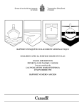
1
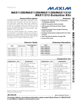
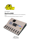
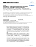
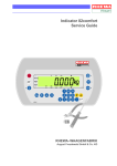
UM10774 EM783 Software Development Kit (SDK) Rev. 2.0 — 16 January 2014 User Manual Document information Info Content Keywords EM783, SDK, User manual, Metrology Abstract This document is the user manual for the EM783 software development kit. UM10774 NXP Semiconductors EM783 Software Development Kit (SDK) Revision history Rev Date Description 2.0 20140116 Updated SDK folder structure in section 2 1.0 20131219 Initial version. Contact information For more information, please visit: http://www.nxp.com For sales office addresses, please send an email to: [email protected] UM10774 User Manual All information provided in this document is subject to legal disclaimers. Rev. 2.0 — 16 January 2014 © NXP B.V. 2014. All rights reserved. 2 of 27 UM10774 NXP Semiconductors EM783 Software Development Kit (SDK) 1. Introduction EM783 is the next generation e-metering chip with a built-in metrology engine. EM783 is built around a low-power, cost-effective and industry standard ARM Cortex-M0 core. The ARM Cortex-M0 runs with a speed up to 48 MHz and offers 4 kB of EEPROM, 32 kB of flash memory, 8 kB of SRAM and various serial peripherals. For design flexibility, NXP offers multiple variants of EM783 as single-channel (SC), multi-channel (MC), single-phase (SP) and three-phase (TP). The variant chips are: EM783-MC3 EM783-MC6 EM783-SC EM783-SP EM783-TP The EM783 reference design evaluation module (EVM) includes an SDK package consisting of a reference energy meter application and metrology library in binary format. The metrology library provides the interface to the EM783 metrology engine. The SDK package is available for download from the NXP website. This document describes the EM783 EVM, the software development kit and the steps to evaluate the EVM. This document also details the calibration procedure for the EVM. This document does not describe the application interface provided by the metrology engine library. For detailed information on… Refer to … EM783 metrology engine API [1] EM783 EVM [2] EM783 FAQ [4] 1.1 Key applications Smart plugs and plug meters Single-phase residential meters DALI/DMX and KNX nodes with metering functionality Industrial sub-meters Power monitors for servers Smart appliances UM10774 User Manual All information provided in this document is subject to legal disclaimers. Rev. 2.0 — 16 January 2014 © NXP B.V. 2014. All rights reserved. 3 of 27 UM10774 NXP Semiconductors EM783 Software Development Kit (SDK) 1.2 Block diagram Fig 1. EM783 block diagram 1.3 Disclaimer This is a prototype for demonstration and evaluation purpose only. The EVM operates at voltages and currents that can result in electrical shock and fire hazard, if used improperly. This EVM should only be operated by qualified personnel familiar with the risks and hazards associated with handling high voltages and currents. The EVM or its components should not be touched when it is energized. Fig 2. Caution 1.4 Support information Use the following link for additional information on EM783. http://www.nxp.com/products/power_management/energy_measurement_ics/series/EM7 83.html For further support on EM783, send an email to [email protected]. 1.5 References [1] EM783 Metrology Engine API document [2] EM783 EVM User Manual [3] EM783 User Manual [4] EM783 FAQ UM10774 User Manual All information provided in this document is subject to legal disclaimers. Rev. 2.0 — 16 January 2014 © NXP B.V. 2014. All rights reserved. 4 of 27 UM10774 NXP Semiconductors EM783 Software Development Kit (SDK) 2. EM783 evaluation module overview This section gives an overview of the EM783 EVM. The EVM includes: EM783 EVM hardware SDK installer EM783_SDK_<x.y>.exe. The installer contains the following folders under the top level SDK folder as shown in Fig 3. Here <x.y> indicates the release number (Note: All paths shown in this document are relative to the top level SDK folder). Fig 3. EM783 SDK folder structure The EVM is equipped with: 1. LCD Panel: To enable the user to view the metrology results 2. UART Port: The UART port on the reference kits must be connected to the host PC using a UART-to-USB cable. This interface can be used for the following: a. Application firmware flashing via EM783 In-System Programming (ISP) interface. Refer to EM783 user manual for more details on ISP interface. b. Debug messaging c. Metrology engine calibration 3. SWD Port: To attach SWD debugger module (the EVM has been tested with Keil ULINK2 SWD debugger). 4. I2C Port: I2C port is used to connect the LCD to EM783. It is also available at the expansion header. 5. SPI Port: SPI port is used to connect the ZigBee module to EM783. It is also available at the expansion header. 6. USB: A USB port is available for PC connectivity. 7. RS485: RS485 port is available for multi-drop communication. This interface can be used to calibrate and test multiple meters connected in parallel. UM10774 User Manual All information provided in this document is subject to legal disclaimers. Rev. 2.0 — 16 January 2014 © NXP B.V. 2014. All rights reserved. 5 of 27 UM10774 NXP Semiconductors EM783 Software Development Kit (SDK) The EM783 is pre-flashed with the reference application firmware and includes the metrology library binary for the evaluation. Warning: Do not try to open the box when it is connected to the mains supply. Do not to connect USB without isolation, which can result in incorrect measurement and cause potential damage to the PC/Laptop. UM10774 User Manual All information provided in this document is subject to legal disclaimers. Rev. 2.0 — 16 January 2014 © NXP B.V. 2014. All rights reserved. 6 of 27 UM10774 NXP Semiconductors EM783 Software Development Kit (SDK) 3. Evaluating EM783 3.1 Building the project 1. Install the SDK package using the installer EM783_SDK_<x.y>.exe. 2. Navigate to the folder src\app\projects\keil. 3. Open the project EM783_<variant>.uvproj using Keil IDE tool; variant refers to EM783 variants (MC3, MC6, SC, SP and TP). 4. Click Project and select Build target to build the project. This generates the EM783_<variant>.hex and EM783_<variant>.axf images in the folder src\app\projects\keil\objs_<variant>. 3.2 Flashing the image 1. Download and install the Flash Magic tool (ensure the tool version is at least 7.51.3222). 2. Ensure the EVM is powered off (SW3 in OFF position). Connect a UART-to-USB serial cable between the connector J12 on the EM783 EVM and the PC. 3. Set the switch SW8 to the ON position. 4. Power up the EVM (SW3 in ON position). 5. Run the Flash Magic tool. 6. Set the target to EM783-<variant> using the select button. 7. Set the COM port to match the port to which the UART serial cable is connected. 8. Set the Baud Rate to 115200 (any baud rate up to 115200 can be used). 9. Set the Interface to None (ISP). 10. In the Hex File tab, browse to the project directory src\app\projects\keil\objs_<variant> and select the file EM783_<variant>.hex. 11. Click on the Start button to program the image onto the EVM. 12. Once the image is flashed, set the switch SW8 to the OFF position. 3.3 Evaluating the EM783 EVM 3.3.1 EM783 EVM power up 1. Ensure the switch SW8 is set to the OFF position. 2. Connect the mains supply to the connectors provided on the front panel of the EVM. Refer to EM783 EVM user manual for the connection details. 3. Power up the EVM (SW3 to ON position). 4. EM783 metrology engine initialization messages are displayed on the UART console. 5. The metrology results for all the channels are displayed on the LCD screen. 3.3.2 EM783 EVM display layout This section describes the format of metrology parameters displayed on the LCD panel for all the EM783 variants. UM10774 User Manual All information provided in this document is subject to legal disclaimers. Rev. 2.0 — 16 January 2014 © NXP B.V. 2014. All rights reserved. 7 of 27 UM10774 NXP Semiconductors EM783 Software Development Kit (SDK) 3.3.2.1 Initialization message On powering up the EVM, the message is displayed on the LCD panel as shown in Fig 4, while the metrology engine is initializing. The figure shown below is an example for the MC3 variant. Fig 4. 3.3.2.2 EM783 initialization message Metrology parameter display Once the initialization is complete the measurement results are displayed on the LCD panel as shown in the figure below. The display consists of four sections: 1. Total Energy and Total power: This section displays the total accumulated energy in kWh and the total power in W. a. The total energy is the sum of the accumulated energy from all the channels and is displayed in XXX.YY format. b. The total power is the sum of the instantaneous power from all the channels and is displayed in XXXXX.YY format. c. The total accumulated energy is displayed for 1 second is as shown in Fig 5. Fig 5. Total accumulated energy display d. This is followed by the display of the total power for the next 1 second as shown in Fig 6. Fig 6. UM10774 User Manual Total instantaneous power display All information provided in this document is subject to legal disclaimers. Rev. 2.0 — 16 January 2014 © NXP B.V. 2014. All rights reserved. 8 of 27 UM10774 NXP Semiconductors EM783 Software Development Kit (SDK) e. Steps ‗c‘ and ‗d‘ are repeated by the metrology engine as long as the meter is running. 2. Channel Voltage: This section displays the instantaneous channel voltage in V. The voltage is displayed in XXX.Y format. 3. Channel Current: This section displays the instantaneous channel current in A. a. The channel number, for which the value of current, voltage and power is being displayed, is identified using the following notation: C<channel id>. b. The channel id ranges from 1 to the maximum number of current channels present in the EM783 variant. c. The current is displayed in X.YY format. 4. Channel Power: This section displays the instantaneous channel power in W. a. The channel power is displayed in XXXX.Y format. b. If the channel power is greater than 9999W, the display changes to XXXXX format to accommodate the maximum value of the power. The channel current and channel power sections display the per channel data and is refreshed every 2 seconds in the following order: Channel-1 → Channel-2 → Channel-3 → Channel-max → Channel-1 and so on. 3.4 SWD pin configuration for EM783 1. EM783 EVM will be pre-flashed with the reference application including the metrology library. The reference application maps the EM783 SWD signals as shown in Table 1. Table 1. EM783 EVM SWD pin mapping SWD Signal EM783 Pin Name Pin Number SWDIO P0_3 11 SWCLK P0_5 19 2. Attach the SWD debugger to the debug connector J1. 3. If the reference application is erased from the flash memory, then on power up, the SWD pins of EM783 reverts to the default mapping as shown in Table 2. Table 2. Default SWD pin mapping SWD Signal EM783 Pin Name Pin Number SWDIO P0_10 25 SWCLK P0_5 19 4. In this mode, the debugger cannot be used to connect to EM783. Use the procedure listed in Section 3.2 to flash the image into EM783. 3.5 Calibration of the metrology engine To calibrate the EM783 EVM, define the option SUPPORT_CALIBRATION in the file src\app\inc\app_config.h. The calibration is performed through the EM783 UART interface using serial terminal emulator software running on the PC. The steps to perform the calibration are shown in the following sections. UM10774 User Manual All information provided in this document is subject to legal disclaimers. Rev. 2.0 — 16 January 2014 © NXP B.V. 2014. All rights reserved. 9 of 27 UM10774 NXP Semiconductors EM783 Software Development Kit (SDK) 3.5.1 Calibration setup 1. Connect the UART serial cable from the connector J12 on the EM783 EVM to the PC. 2. Run the serial terminal emulator software. 3. Click Setup and select Serial port. Set Port to match the COM port to which the UART serial cable is connected. Set Baud rate to 57600, Data to 8 bits, Parity to none, Stop bits to 1 and Flow control to none. 4. Enable Local echo option in the serial terminal. 5. Connect the EM783 EVM to a reference power supply and a resistive load. 3.5.2 Calibration commands This section lists the set of commands available for calibrating the EVM. These commands can be entered into the serial terminal any time after the metrology initialization is complete. The number of voltage channels (NR_VOLTAGE_CHANNELS), current channels (NR_CURRENT_CHANNELS) and the number of gain channels (total number of current channels including the high and low gain channels – NR_GAIN_CHANNELS) for the EM783 variants as shown in Table 3. Table 3. EM783 variant configuration parameters Variant NR_VOLTAGE_CHANNELS NR_CURRENT_CHANNELS NR_GAIN_CHANNELS MC3 1 3 6 MC6 1 6 6 SC 1 1 2 SP 1 2 4 TP 3 3 3 The calibration commands are described below. 1. Display Metrology result. Table 4. Field UM10774 User Manual Calibration command – display metrology result Value Command CDM Description This command displays the metrology results on the serial terminal. Response The following metrology parameters are displayed on the serial terminal: RMS Voltage for NR_VOLTAGE_CHANNELS in Volts RMS Current for NR_CURRENT_CHANNELS in Amperes Active Power for NR_CURRENT_CHANNELS in Watts Fundamental Reactive Power for NR_CURRENT_CHANNELS in VAR Energy in Ws accumulated during the previous integration period for NR_CURRENT_CHANNELS Phase angle for NR_CURRENT_CHANNELS in degrees Mains frequency in Hz EM783 die temperature in degree Celsius Duration of the last integration period in seconds Positive Peak Voltage for NR_VOLTAGE_CHANNELS in volts All information provided in this document is subject to legal disclaimers. Rev. 2.0 — 16 January 2014 © NXP B.V. 2014. All rights reserved. 10 of 27 UM10774 NXP Semiconductors EM783 Software Development Kit (SDK) Field Fig 7. Value Negative Peak Voltage for NR_VOLTAGE_CHANNELS in volts Positive Peak Current for NR_CURRENT_CHANNELS in Amperes Negative Peak Current for NR_CURRENT_CHANNELS in Amperes CDM command output for MC3 variant 2. Display Offsets. Calibration command – display offset corrections Value Table 5. Field Command CDO Description This command displays the values of the offset corrections for all the current and the voltage channels. Response The following offset values are displayed on the serial terminal: Fig 8. UM10774 User Manual NR_VOLTAGE_CHANNELS offsets for the voltage inputs NR_GAIN_CHANNELS offsets for the current inputs CDO command output for MC3 variant All information provided in this document is subject to legal disclaimers. Rev. 2.0 — 16 January 2014 © NXP B.V. 2014. All rights reserved. 11 of 27 UM10774 NXP Semiconductors EM783 Software Development Kit (SDK) 3. Display Ranges. Calibration command – display ranges Value Table 6. Field Command CDR Description This command displays the calibration parameters (peak-to-peak current and voltage ranges) on the serial terminal. Response The following ranges are displayed on the serial terminal: Fig 9. Ranges for NR_VOLTAGE_CHANNELS voltage inputs Ranges for NR_GAIN_CHANNELS current inputs Phase correction value for NR_GAIN_CHANNELS current inputs CDR command output for MC3 variant 4. Set offset correction for current and voltage channels. Table 7. Field Calibration command – set offset correction parameter Value Command CSO Description This command sets the offset calibration parameter for a channel into the metrology engine. The format of the command is: CSO <channel_type> <channel_number> <offset> Parameters V – Voltage channel channel_type I – Current channel channel_number The channel number should be input as listed in the table below. The table uses the following notations: H – High Gain Channel L – Low Gain Channel 1 to 6 – Channel number Voltage channel number must be from 1 to NR_VOLTAGE_CHANNELS Current channel number must be as given in the table below: UM10774 User Manual All information provided in this document is subject to legal disclaimers. Rev. 2.0 — 16 January 2014 © NXP B.V. 2014. All rights reserved. 12 of 27 UM10774 NXP Semiconductors EM783 Software Development Kit (SDK) Field Value MC3 MC6 SC SP TP 1H 1 1H 1H 1 1L 2 1L 1L 2 2H 3 2H 3 2L 4 2L 3H 5 3L 6 Offset New offset value Response OK – Success Bad parameter – Incorrect value of offset correction Examples: CSO V1 1 — Set the offset of the voltage channel 1 to 1 CSO I1H -1 — Set the offset of the high gain current channel 1 to -1 CSO I2L -3 — Set the offset of the low gain current channel 2 to -3 5. Calibrate voltage channel. Table 8. Field Calibration command – calibrate voltage range for voltage channel Value Command CSV Description This command calibrates the voltage channel. The format of the command is: CSV <channel_number> <reference_rms_voltage> Parameters channel_number Voltage channel number must be a value from 1 to NR_VOLTAGE_CHANNELS. reference_rms_vo RMS voltage obtained from the reference meter in Volts ltage OK – Success Response Bad parameter – Incorrect range parameter Examples: CSV 1 230 — Calibrate the voltage channel 1 to reference RMS voltage of 230V 6. Calibrate current channel. Table 9. Field Calibration command – calibrate current range for current channel Value Command CSI Description This command calibrates the current channel. The format of the command is: CSI <channel_number> <reference_rms_current> Parameters channel_number UM10774 User Manual The channel number should be specified as listed in the table below. The table uses the following notations: All information provided in this document is subject to legal disclaimers. Rev. 2.0 — 16 January 2014 © NXP B.V. 2014. All rights reserved. 13 of 27 UM10774 NXP Semiconductors EM783 Software Development Kit (SDK) Field Value H – High Gain Channel L – Low Gain Channel 1 to 6 – Channel number MC3 MC6 SC SP TP 1H 1 1H 1H 1 1L 2 1L 1L 2 2H 3 2H 3 2L 4 2L 3H 5 3L 6 reference_rms_cu RMS current obtained from the reference meter in Ampere rrent OK – Success Response Bad parameter – Incorrect value of offset correction Examples: CSI 1 24 — Calibrate channel 1 on MC6 variant to reference RMS current of 24A CSI 2L 24 — Calibrate low gain channel 2 on MC3 variant to reference RMS current of 24A 7. Calibrate phase correction for current channel. Table 10. Field Calibration command – calibrate phase correction for current channel Value Command CSP Description This command calibrates the phase correction for a current channel. The format of the command is: CSP <channel_number> Parameters channel_number The channel number should be specified as listed in the table below. The table uses the following notations: H – High Gain Channel L – Low Gain Channel 1 to 6 – Channel number UM10774 User Manual MC3 MC6 SC SP TP 1H 1 1H 1H 1 1L 2 1L 1L 2 2H 3 2H 3 2L 4 2L 3H 5 3L 6 phase correction New phase correction value for the current channel in radian Response OK – Success All information provided in this document is subject to legal disclaimers. Rev. 2.0 — 16 January 2014 © NXP B.V. 2014. All rights reserved. 14 of 27 UM10774 NXP Semiconductors EM783 Software Development Kit (SDK) Field Value Bad parameter – Incorrect value of offset correction Examples: CSP 6 — Calibrate phase correction for channel 6 on MC6 variant CSP 3H — Calibrate high gain channel 3 on MC3 variant 8. Program Offsets into EEPROM. Table 11. Field Calibration command – program Offsets Value Command CPO Description This command programs the offset values into the EEPROM. Response OK – Success 9. Program Ranges into EEPROM. Table 12. Field Calibration command – program Ranges Value Command CPR Description This command programs the range values into the EEPROM. Response OK – Success 3.5.3 Calibration procedure The calibration is performed with the following steps in the order listed below: 1. Calibrate offsets of all the voltage channels 2. Calibrate offsets of all the current channels 3. Calibrate voltage ranges of all the voltage channels 4. Calibrate current ranges of all the current channels 5. Calibrate phase correction of all the current channels 3.5.3.1 Calibration of voltage channel offset 1. Power up the EVM. 2. Wait for the metrology engine to complete the initialization and display the metrology parameters in the LCD. 3. Set the offset parameter for the voltage channel being calibrated to 0 using the CSO command. Example: To set offset of voltage channel 1 to 0 enter the following command in the serial terminal: CSO V 1 0 4. Use the CDM command in the serial terminal to display the metrology results. Note down the positive peak voltage and the negative peak voltage values. 5. If the values of the positive peak voltage and the negative peak voltage for the channel are different, then the offset calibration needs to be performed. UM10774 User Manual All information provided in this document is subject to legal disclaimers. Rev. 2.0 — 16 January 2014 © NXP B.V. 2014. All rights reserved. 15 of 27 UM10774 NXP Semiconductors EM783 Software Development Kit (SDK) 6. Adjust the value of the offset for the channel being calibrated using the command CSO in the serial terminal until both the positive peak and the negative peak voltage values are almost the same. 7. Program the new offset value into the EEPROM by entering the command CPO in the serial terminal. 3.5.3.2 Calibration of current channel offset 1. Set the offset parameter for the current channel being calibrated to 0 using the CSO command. Example: To set offset of the high gain current path of channel 1 of MC3 variant to 0 enter the following command in the serial terminal: CSO I 1H 0 2. Use the CDM command in the serial terminal to display the metrology results. Note down the positive peak current and the negative peak current values. 3. If the values of the positive peak current and the negative peak current for the channel are different, then the offset calibration needs to be performed. 4. Adjust the value of the offset using the command CSO in the serial terminal until both the positive peak and the negative peak current values are almost the same. 5. Program the new offset value into the EEPROM by entering the command CPO in the serial terminal. 3.5.3.3 Calibration of voltage range 1. Use the CDM command in the serial terminal to display the metrology results and note down the measured RMS voltage for the channel being calibrated. 2. If the error in the measured RMS voltage with respect to the reference meter reported RMS voltage is more than the allowed range, then the voltage range calibration needs to be done. 3. Use the CSV command to calibrate the voltage channel for the reference RMS voltage. 4. Program the new voltage calibration parameter into the EEPROM by entering the command CPR in the serial terminal. 3.5.3.4 Calibration of current range 1. Enter the command CDM in the serial terminal to display the metrology results and note down the measured RMS current for the channel being calibrated. 2. If the error in the measured RMS current with respect to the reference meter reported RMS current is more than the allowed range, then the current range calibration needs to be done. 3. Use the CSI command to calibrate the current channel for the reference RMS current. 4. Program the new current calibration parameter into the EEPROM by entering the command CPR in the serial terminal. 3.5.3.5 Calibration of phase correction 1. Use the CSP command to calibrate the phase correction for a current channel. 2. Verify that the value of the fundamental reactive power Q1 is as close to 0 as possible using the CDM command in the serial terminal. 3. Program the new phase correction factor into the EEPROM by entering the command CPR in the serial terminal. UM10774 User Manual All information provided in this document is subject to legal disclaimers. Rev. 2.0 — 16 January 2014 © NXP B.V. 2014. All rights reserved. 16 of 27 UM10774 NXP Semiconductors EM783 Software Development Kit (SDK) 4. EM783 SDK configuration The EM783 EVM provides the following interfaces to the external world to communicate with the EM783: 1. UART: This interface is available at connector J12 and is used for debug messages, ISP flashing and calibration of the metrology engine by the reference application. 2. USB: This interface is available at connector J7. The USB controller MAX3420EETG+ is connected to EM783 via the SPI interface. The reference application provides a SPI driver and a CDC class driver for MAX3420E controller. 3. Wireless: EM783 EVM also provides wireless connectivity using the NXP JN5148 ZigBee module. The ZigBee module is interfaced to the EM783 via the I2C/SPI-toUART Bridge chip SC16IS752IBS. The SDK provides both SPI and I2C drivers to communicate with the ZigBee module. 4. RS485: EM783 UART data can be routed to the RS485 transceiver on the EVM. The RS485 signals are available at connector J8. 5. I2C: EM783 I2C interface is available at the expansion connector J4. 6. SPI: EM783 SPI interface is available at the expansion connector J4. The EM783 SDK provides the following configuration options to enable or disable the required communication interfaces. Table 13. EM783 SDK configuration parameters Defined in app\inc\app_config.h Sl. Configuration option Default value Valid values No. Purpose 12000000, 24000000, 36000000, 48000000, Sets the EM783_CORE_FREQUENCY_HZ. EM783_CORE_FREQUENCY_HZ Is defined in comps\cmsis\CMSIS_3_01\CM0\DeviceSupport\EM7 8X\system_EM78x.c 1 EM78X_CORE_CLOCK SPEED_HZ 2 EM78X_TICK_RATE_HZ 1000 Application defined Configures the tick rate of the Cortex M0 Systick timer. 3 LED_BLINK_RATE_IN_ MS Application defined Rate at which LED D5 is blinked in ms. 4 LCD_REFRESH_RATE_ IN_MS 1000 Application defined Rate at which the metrology parameters are refreshed in the LCD in ms. 5 EM783_CONSOLE_BAU DRATE 57600 Application defined Baud rate of the EM783 console interface 6 I2C_INTERRUPT_PRIO RITY 3 2 or 3 I2C driver interrupt priority 7 UART_INTERRUPT_PRI ORITY 3 2 or 3 UART driver interrupt priority 8 TMR16B0_INTERRUPT _PRIORITY 3 2 or 3 16-bit Timer B0 interrupt priority (used by the KiloWatt-Hour (KWH) pulser module 9 SSP_INTERRUPT_PRIO RITY 3 2 or 3 SSP driver interrupt priority 10 SYSTICK_INTERRUPT_ PRIORITY 3 2 or 3 Systick timer interrupt priority 11 GPIO_INTERRUPT_PRI 3 2 or 3 GPIO interrupt priority UM10774 User Manual 36000000 250 All information provided in this document is subject to legal disclaimers. Rev. 2.0 — 16 January 2014 © NXP B.V. 2014. All rights reserved. 17 of 27 UM10774 NXP Semiconductors EM783 Software Development Kit (SDK) Sl. No. Configuration option Default value Valid values Purpose 12 METROLOGY_DEFAUL T_INTEGRATION_PERI OD 130 Refer EM783_FAQ for recommended values Number of mains periods to be used in the calculation of the metrology parameters 13 METROLOGY_DEFAUL T_MVDD 3300 Application defined EM783 VDD voltage in mV. Defined Defined or undefined Define this macro to enable the metrology engine calibration interface. Undefined this macro to disable metrology engine the calibration interface. Define this macro to enable logging metrology data into a circular buffer in the EEPROM. Undefined this macro to disable the logger module. ORITY 14 SUPPORT_CALIBRATI ON 15 SUPPORT_LOGGER Disabled Defined or undefined 16 LOG_RATE_S (10 * 60) Application defined Defines the rate in seconds at which the metrology data are logged into the EEPROM. Enabled Enabled or disabled Define this macro to enable debug messaging on the UART interface Undefine this macro to disable debug messaging on the UART interface Disabled Enabled or disabled Define this macro to enable the KWH pulse module Undefine this macro to disable the KWH pulse module 17 SUPPORT_UART_DEB UG 18 SUPPORT_KWH_PULS ER 1000, 2000, 19 KWH_PULSE_RATE_D EFAULT 2000 3000, Sets the pulse rate of the KWH pulse output in number of pulses per kWH of energy 20 SUPPORT_LCD Enabled Enabled or disabled Define this macro to enable the LCD driver Undefine this macro to disable the LCD driver 21 SUPPORT_MAX3420E Disabled Enabled or disabled Define this macro to enable the MAX3420E driver Undefine this macro to disable the MAX3420E driver 22 MAX3420E_INTERRUP T_PIN 4 Defines the GPIO pin number to which the GPIO pin number MAX3420E interrupt pin is connected. 23 SUPPORT_SC16IS752 Disabled Enabled or disabled Define this macro to enable the SC16IS752 driver 24 SC16IS752_BAUDRATE 38400 Application defined Baud rate for the SC16IS752 UART interface 25 SC16IS752_I2C_INTER FACE 1 1 or 0 Select I2C interface for communication between EM783 and SC16IS752 26 SC16IS752_SSP_INTER FACE 0 1 or 0 Select SSP interface for communication between EM783 and SC16IS752 SUPPORT_UART Enabled Enabled or disabled Define this macro to enable the EM783 UART driver Undefine this macro to disable the EM783 UART driver UART_BAUDRATE EM783_CONS Standard baud OLE_BAUDRA rates up to TE 115200 27 28 29 SUPPORT_I2C UM10774 User Manual Enabled Enabled or disabled Defines the baud rate for the EM783 UART interface Define this macro to enable the I2C driver Undefine this macro to disable the I2C driver All information provided in this document is subject to legal disclaimers. Rev. 2.0 — 16 January 2014 © NXP B.V. 2014. All rights reserved. 18 of 27 UM10774 NXP Semiconductors EM783 Software Development Kit (SDK) Sl. No. Configuration option Default value Valid values Purpose 30 SUPPORT_SSP Disabled Enabled or disabled Define this macro to enable the SSP driver Undefine this macro to disable the SSP driver 31 SSP_CLOCKSPEED_HZ 1000000 Application defined SSP interface clock speed. 32 SSP_USE_CS 0 Application defined Set this to 1 to use the SSP slave select signal from the controller Set this to 0 to use P0_18 (in GPIO mode) for slave select 33 SSP_CS_GPIO 18 Application defined GPIO used as chip select for the EM783 SSP interface Enabled or disabled Define this macro to enable stack usage check feature. With this option enabled, the stack is filled with known pattern (STACK_MEM_INIT_PATTERN). Exercise the system to ensure the greatest stack depth is achieved. Halt the system using debugger and examine the stack memory to determine how much of the stack is used. Any pattern Stack memory initialization pattern 34 SUPPORT_STACK_CH ECK 35 STACK_MEM_INIT_PAT TERN 0xBAADF00D Disabled [1] KWH pulse module uses P0_4 for KWH pulse output, this is also the pin used as the interrupt pin for MAX3420E USB controller. Hence on the EM783 EVM, SUPPORT_MAX3420E and SUPPORT_KWH_PULSER cannot be enabled simultaneously. [2] SUPPORT_SSP needs to be defined to enable SUPPORT_MAX3420E. [3] SUPPORT_I2C needs to be defined to enable SUPPORT_LCD. [4] SUPPORT_UART_DEBUG needs to be defined to enable SUPPORT_CALIBRATION. 5. EM783 temperature compensation 5.1 Need for temperature compensation EM783 EVM can be operated over a wide temperature range. The performance characteristics of the EVM vary at different temperatures. This results in the variation of the accuracy of the metrology measurement output, when the EVM is operated at different temperature conditions. Temperature compensation is used to improve the accuracy in the metrology measurement output when the EVM is operated at temperatures other than the ambient temperature at which the unit is calibrated. 5.2 Temperature compensation procedure The temperature compensation procedure involves measuring a fixed reference current with the EVM at various temperatures and applying the appropriate correction factor. The temperature compensation has to be performed for voltage, current and phase angle of all the channels separately. 5.2.1 Voltage and current compensation The temperature compensation procedure for the voltage channels and the current channels are the same. The temperature compensation procedure for one current channel is illustrated in the steps below. The setup used for the calibration is reused to derive the correction factor for the temperature compensation; see Section 3.5.3. 1. Enclose the EVM in a temperature chamber UM10774 User Manual All information provided in this document is subject to legal disclaimers. Rev. 2.0 — 16 January 2014 © NXP B.V. 2014. All rights reserved. 19 of 27 UM10774 NXP Semiconductors EM783 Software Development Kit (SDK) 2. Set the reference current to 5A (the effect of variation in the temperature is more towards lower current. Hence set the reference current to about 20% of the range of the current that can be measured with the channel). 3. Set the temperature within the temperature chamber to 80C. 4. Note down the value of the current reported by the metrology engine for the channel being characterized. 5. Repeat steps 2 to 4 by setting the temperature to different values over the entire range in which the EVM is used. 6. An example set of measurement data for a current channel at different temperatures from 0C to 80C is shown in Table 14. 7. Compute the ideal correction factor C_ideal as shown in the table below. Plot a curve of the ideal correction factor against the temperature as shown in Fig 10. Current Correction factor (%) Vs Temperature 2 y = 0.0428x - 1.3415 1 Correction Factor - Ideal 0 0 10 20 30 40 50 60 70 80 Correction factor- Best Fit -1 -2 Fig 10. Plot of correction factor for current versus temperature 8. Overlay a best fit curve through the points of the ideal correction factor points. In the above example, the curve is defined by y = 0.0428x – 1.3415. 9. Compute the new calibration factor using the correction factor, as shown Table 14. UM10774 User Manual All information provided in this document is subject to legal disclaimers. Rev. 2.0 — 16 January 2014 © NXP B.V. 2014. All rights reserved. 20 of 27 UM10774 NXP Semiconductors EM783 Software Development Kit (SDK) Table 14. EM783 temperature compensation example for current I1L (A) = 5 ; I1Lpp = 3.04876 T (C) I1Lm (A) Corr_ideal Corr_estimated I1Lpp_comp 80 4.91 1.832994 2.082500 3.112250 70 4.924 1.543461 1.654500 3.099202 60 4.9286 1.448687 1.226500 3.086153 50 4.94128 1.188356 0.798500 3.073104 40 4.99134 0.173501 0.370500 3.060056 25 5 0.000000 -0.271500 3.040483 20 5.034 -0.675407 -0.485500 3.033958 10 5.052 -1.029295 -0.913500 3.020910 0 5.0699 -1.378725 -1.341500 3.007861 Following notations are used in this table Notation Formula Meaning I1L Test current applied to channel I1L to derive the temperature compensation formula l1Lpp Calibration factor for the channel I1L obtained after calibration T Temperature to which the EVM is subjected to in degree Celsius I1Lm Measured current in A from channel I1L at the set temperature Corr_ideal (I1L – I1Lm) * 100 / I1L Ideal correction factor Corr_estimated (0.0428 * T) - 1.3415 Correction factor estimated using the best fir curve I1Lpp_comp I1Lpp * (1 + C) Corrected calibration parameter 5.2.2 Phase angle correction factor compensation The temperature compensation procedure for the phase angle correction factor is similar to the procedure for the current and voltage compensation. The example calculation for the phase angle correction factor temperature compensation is shown in Fig 11 and Table 15. UM10774 User Manual All information provided in this document is subject to legal disclaimers. Rev. 2.0 — 16 January 2014 © NXP B.V. 2014. All rights reserved. 21 of 27 UM10774 NXP Semiconductors EM783 Software Development Kit (SDK) Phase Correction factor (%) Vs Temperature 0.00020 0.00015 0.00010 0.00005 Correction Factor - Ideal y = -3E-06x + 7E-05 0.00000 0 10 20 30 40 50 60 70 80 -0.00005 Correction factor- Best Fit -0.00010 -0.00015 -0.00020 Fig 11. Plot of correction factor for phase angle versus temperature Table 15. EM783 temperature compensation example for phase angle Phi1L (rads) = 0.002345; Deltaphi1L (rads) = -0.069813 T (C) Phi1Lm (rads) Corr_ideal (rads) Corr_estimated (rads) Deltaphi1l_comp (rads) 80 0.002549 -0.000204 -0.000170 -0.069983 70 0.002501 -0.000156 -0.000140 -0.069953 60 0.002483 -0.000138 -0.000110 -0.069923 50 0.002452 -0.000107 -0.000080 -0.069893 40 0.002416 -0.000071 -0.000050 -0.069863 25 0.002345 0.000000 -0.000005 -0.069818 20 0.002341 0.000004 0.000010 -0.069803 10 0.002338 0.000007 0.000040 -0.069773 0 0.0022452 0.000100 0.000070 -0.069743 Following notations are used in this table Notation UM10774 User Manual Formula Meaning Phi1L Phase angle value measured for channel 1L for power factor 1 Deltaphi1L Phase angle correction factor for channel 1L obtained after calibration T Temperature to which the EVM is subjected to in degree Celsius Phi1Lm Measured phase angle in radians from channel 1L at the set temperature All information provided in this document is subject to legal disclaimers. Rev. 2.0 — 16 January 2014 © NXP B.V. 2014. All rights reserved. 22 of 27 UM10774 NXP Semiconductors EM783 Software Development Kit (SDK) Corr_ideal (Pref - Pm) Corr_estimated (-3e-6 * T) + 7e-5 Correction factor estimated using the best fir curve Deltaphi1L_comp Pcal + C UM10774 User Manual Ideal correction factor Corrected calibration parameter All information provided in this document is subject to legal disclaimers. Rev. 2.0 — 16 January 2014 © NXP B.V. 2014. All rights reserved. 23 of 27 UM10774 NXP Semiconductors EM783 Software Development Kit (SDK) 6. Legal information 6.1 Definitions Draft — The document is a draft version only. The content is still under internal review and subject to formal approval, which may result in modifications or additions. NXP Semiconductors does not give any representations or warranties as to the accuracy or completeness of information included herein and shall have no liability for the consequences of use of such information. 6.2 Disclaimers Limited warranty and liability — Information in this document is believed to be accurate and reliable. However, NXP Semiconductors does not give any representations or warranties, expressed or implied, as to the accuracy or completeness of such information and shall have no liability for the consequences of use of such information. In no event shall NXP Semiconductors be liable for any indirect, incidental, punitive, special or consequential damages (including - without limitation lost profits, lost savings, business interruption, costs related to the removal or replacement of any products or rework charges) whether or not such damages are based on tort (including negligence), warranty, breach of contract or any other legal theory. Notwithstanding any damages that customer might incur for any reason whatsoever, NXP Semiconductors‘ aggregate and cumulative liability towards customer for the products described herein shall be limited in accordance with the Terms and conditions of commercial sale of NXP Semiconductors. Right to make changes — NXP Semiconductors reserves the right to make changes to information published in this document, including without limitation specifications and product descriptions, at any time and without notice. This document supersedes and replaces all information supplied prior to the publication hereof. Suitability for use — NXP Semiconductors products are not designed, authorized or warranted to be suitable for use in life support, life-critical or safety-critical systems or equipment, nor in applications where failure or malfunction of an NXP Semiconductors product can reasonably be expected to result in personal injury, death or severe property or environmental damage. NXP Semiconductors accepts no liability for inclusion and/or use of NXP Semiconductors products in such equipment or applications and therefore such inclusion and/or use is at the customer‘s own risk. Applications — Applications that are described herein for any of these products are for illustrative purposes only. NXP Semiconductors makes no representation or warranty that such applications will be suitable for the specified use without further testing or modification. Customers are responsible for the design and operation of their applications and products using NXP Semiconductors products, and NXP Semiconductors accepts no liability for any assistance with applications or UM10774 User Manual customer product design. It is customer‘s sole responsibility to determine whether the NXP Semiconductors product is suitable and fit for the customer‘s applications and products planned, as well as for the planned application and use of customer‘s third party customer(s). Customers should provide appropriate design and operating safeguards to minimize the risks associated with their applications and products. NXP Semiconductors does not accept any liability related to any default, damage, costs or problem which is based on any weakness or default in the customer‘s applications or products, or the application or use by customer‘s third party customer(s). Customer is responsible for doing all necessary testing for the customer‘s applications and products using NXP Semiconductors products in order to avoid a default of the applications and the products or of the application or use by customer‘s third party customer(s). NXP does not accept any liability in this respect. Export control — This document as well as the item(s) described herein may be subject to export control regulations. Export might require a prior authorization from competent authorities. Evaluation products — This product is provided on an ―as is‖ and ―with all faults‖ basis for evaluation purposes only. NXP Semiconductors, its affiliates and their suppliers expressly disclaim all warranties, whether express, implied or statutory, including but not limited to the implied warranties of noninfringement, merchantability and fitness for a particular purpose. The entire risk as to the quality, or arising out of the use or performance, of this product remains with customer. In no event shall NXP Semiconductors, its affiliates or their suppliers be liable to customer for any special, indirect, consequential, punitive or incidental damages (including without limitation damages for loss of business, business interruption, loss of use, loss of data or information, and the like) arising out the use of or inability to use the product, whether or not based on tort (including negligence), strict liability, breach of contract, breach of warranty or any other theory, even if advised of the possibility of such damages. Notwithstanding any damages that customer might incur for any reason whatsoever (including without limitation, all damages referenced above and all direct or general damages), the entire liability of NXP Semiconductors, its affiliates and their suppliers and customer‘s exclusive remedy for all of the foregoing shall be limited to actual damages incurred by customer based on reasonable reliance up to the greater of the amount actually paid by customer for the product or five dollars (US$5.00). The foregoing limitations, exclusions and disclaimers shall apply to the maximum extent permitted by applicable law, even if any remedy fails of its essential purpose. 6.3 Trademarks Notice: All referenced brands, product names, service names and trademarks are property of their respective owners. All information provided in this document is subject to legal disclaimers. Rev. 2.0 — 16 January 2014 © NXP B.V. 2014. All rights reserved. 24 of 27 UM10774 NXP Semiconductors EM783 Software Development Kit (SDK) 7. List of figures Fig 1. Fig 2. Fig 3. Fig 4. Fig 5. Fig 6. Fig 7. EM783 block diagram ....................................... 4 Caution ............................................................. 4 EM783 SDK folder structure ............................. 5 EM783 initialization message............................ 8 Total accumulated energy display ..................... 8 Total instantaneous power display .................... 8 CDM command output for MC3 variant ........... 11 UM10774 User Manual Fig 8. Fig 9. Fig 10. Fig 11. CDO command output for MC3 variant ...........11 CDR command output for MC3 variant ...........12 Plot of correction factor for current versus temperature .....................................................20 Plot of correction factor for phase angle versus temperature .....................................................22 All information provided in this document is subject to legal disclaimers. Rev. 2.0 — 16 January 2014 © NXP B.V. 2014. All rights reserved. 25 of 27 UM10774 NXP Semiconductors EM783 Software Development Kit (SDK) 8. List of tables Table 1. Table 2. Table 3. Table 4. Table 5. Table 6. Table 7. Table 8. EM783 EVM SWD pin mapping ........................ 9 Default SWD pin mapping ................................. 9 EM783 variant configuration parameters ........ 10 Calibration command – display metrology result ........................................................................ 10 Calibration command – display offset corrections ...................................................... 11 Calibration command – display ranges ........... 12 Calibration command – set offset correction parameter........................................................ 12 Calibration command – calibrate voltage range for voltage channel.......................................... 13 UM10774 User Manual Table 9. Table 10. Table 11. Table 12. Table 13. Table 14. Table 15. Calibration command – calibrate current range for current channel ..........................................13 Calibration command – calibrate phase correction for current channel..........................14 Calibration command – program Offsets .........15 Calibration command – program Ranges ........15 EM783 SDK configuration parameters ............17 EM783 temperature compensation example for current ............................................................. 21 EM783 temperature compensation example for phase angle.....................................................22 All information provided in this document is subject to legal disclaimers. Rev. 2.0 — 16 January 2014 © NXP B.V. 2014. All rights reserved. 26 of 27 UM10774 NXP Semiconductors EM783 Software Development Kit (SDK) 9. Contents 1. 1.1 1.2 1.3 1.4 1.5 2. 3. 3.1 3.2 3.3 3.3.1 3.3.2 3.3.2.1 3.3.2.2 3.4 3.5 3.5.1 3.5.2 3.5.3 3.5.3.1 3.5.3.2 3.5.3.3 3.5.3.4 3.5.3.5 4. 5. 5.1 5.2 5.2.1 5.2.2 6. 6.1 6.2 6.3 7. 8. 9. Introduction ......................................................... 3 Key applications ................................................. 3 Block diagram .................................................... 4 Disclaimer .......................................................... 4 Support information ............................................ 4 References ......................................................... 4 EM783 evaluation module overview .................. 5 Evaluating EM783 ................................................ 7 Building the project............................................. 7 Flashing the image ............................................. 7 Evaluating the EM783 EVM ............................... 7 EM783 EVM power up ....................................... 7 EM783 EVM display layout ................................ 7 Initialization message ......................................... 8 Metrology parameter display .............................. 8 SWD pin configuration for EM783 ...................... 9 Calibration of the metrology engine .................... 9 Calibration setup .............................................. 10 Calibration commands ..................................... 10 Calibration procedure ....................................... 15 Calibration of voltage channel offset ................ 15 Calibration of current channel offset ................. 16 Calibration of voltage range ............................. 16 Calibration of current range .............................. 16 Calibration of phase correction......................... 16 EM783 SDK configuration................................. 17 EM783 temperature compensation .................. 19 Need for temperature compensation ................ 19 Temperature compensation procedure ............ 19 Voltage and current compensation................... 19 Phase angle correction factor compensation ... 21 Legal information .............................................. 24 Definitions ........................................................ 24 Disclaimers....................................................... 24 Trademarks ...................................................... 24 List of figures..................................................... 25 List of tables ...................................................... 26 Contents ............................................................. 27 Please be aware that important notices concerning this document and the product(s) described herein, have been included in the section 'Legal information'. © NXP B.V. 2014. . All rights reserved. For more information, please visit: http://www.nxp.com For sales office addresses, please send an email to: [email protected] Date of release: 16 January 2014 Document identifier: UM10774