1
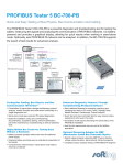
FBT-11
Fieldbus Fault Generator
User Manual
502-846 FBT-11 User Manual Rev A.0
1
© Copyright Relcom, Inc. 2012
All rights reserved. No part of this manual may be reproduced,
photocopied, stored on a retrieval system or transmitted without
the express prior written consent of Relcom, Inc.
Relcom, Inc.
2221 Yew St.
Forest Grove, OR 97116
USA
Tel: (503) 357-5607
Fax: (503) 357-0491
www.relcominc.com
2
502-846 FBT-11 User Manual Rev A.0
Table of Contents
I.
Table of Contents
I. Table of Contents .............................................................. 3
II. Introduction ........................................................................ 4
III. Operation ........................................................................... 5
Startup .................................................................................. 5
Inducing Bus Noise ............................................................... 5
Internal Current Load............................................................. 7
Shield Short .......................................................................... 7
Signal Attenuation ................................................................. 8
IV. Accessories ....................................................................... 9
V. Specifications .................................................................. 10
VI. Service ............................................................................ 11
VII. Warranty .......................................................................... 12
VIII. Revision History ............................................................... 13
502-846 FBT-11 User Manual Rev A.0
3
Introduction
Revision History
II.
VIII. Revision History
Introduction
The FBT-11 Fieldbus Fault Generator is a Foundation Fieldbus
physical segment tool designed to test the susceptibility of a
segment to various faults that may occur in the field. It allows
both engineering and service technicians to determine the health
of fieldbus segments.
This manual was current at the time of printing. Go to
www.relcominc.com for an electronic copy of the latest version of
this manual. Further information on fieldbus is available in the
Fieldbus Wiring Guide, also available on the website.
Revision
Date
Description
A
05/21/2012
Original Release
Relcom, Inc.
2221 Yew St.
Forest Grove, OR 97116
USA
Summary of Features
The Fault Generator includes the following features:
• Places variable frequency and amplitude noise onto the bus
• Attenuates bus signals
• Simulates the current draw of adding up to 5 standard 20mA
Fieldbus devices on a segment
• Causes shield shorts to the positive and negative Fieldbus
lines
4
502-846 FBT-11 User Manual Rev A.0
Tel: (503) 357-5607
Fax: (503) 357-0491
www.relcominc.com
502-846 FBT-11 User Manual Rev A.0
13
Warranty
Operation
VII. Warranty
III.
Relcom, Inc. warrants the FBT-11 to perform as described in this
manual under normal use for a period of one year after delivery
to the original purchaser. This warranty does not apply if the
Fault Generator has been disassembled, modified or used for
purposes other than those described in this manual.
Operation
The Fault Generator draws a minimum of 14mA of
current from the fieldbus segment it is connected
to. Verify adequate current is available before
connecting the Fault Generator or bus communications may
be impacted.
Upon verification of any defect, Relcom, Inc. shall, at its option,
repair or replace the defective unit.
Startup
In no event does Relcom, Inc. assume liability for incidental or
consequential damages. This warranty is the extent of the
obligation or liability assumed by Relcom, Inc., and no other
warranty or guarantee is either expressed or implied.
Relcom, Inc. reserves the right to make design changes to the
FBT-11 without notice and with no obligation to make the same
or similar changes to units previously manufactured.
Relcom, Inc. has made every effort to assure the accuracy of the
information contained in this manual. Relcom is not, however,
responsible for any errors or omissions. Please contact us with
any questions or suggestions.
Relcom, Inc.
2221 Yew St.
Forest Grove, OR 97116
USA
Tel: (503) 357-5607
Fax: (503) 357-0491
Email: [email protected]
www.relcominc.com
12
502-846 FBT-11 User Manual Rev A.0
The Fault Generator is powered by the segment it is connected
to and turns on automatically. Begin by connecting the color
coded leads to both the FBT-11 as well as the fieldbus segment
you wish to test. If connected correctly, a green “Power” LED
will illuminate, signifying the segment is device is ready to use.
To ensure the segment is affected as little as possible upon
power-up, set the controls of the device as follows:
Noise Frequency: OFF
Current Load: 1
Signal Atten.: 1
Shield Short: None
Current Load: OFF
Noise Amp.: 10
The input of the Fault Generator is reverse polarity and fuse
protected.
Inducing Bus Noise
Sinusoidal noise may be introduced onto the bus by selecting
one of four settings on the “Noise Frequency” dial. Changing the
setting on this dial changes the frequency and type of noise on
the bus. See table 1 for details.
502-846 FBT-11 User Manual Rev A.0
5
Operation
Setting
OFF
LF
FF
FFgated
HF
Service
Frequency
N/A
500 Hz
20 kHz
20 kHz
200 kHz
Noise Type
None
Constant Sinusoidal
Constant Sinusoidal
Pulsed Sinusoidal
Constant Sinusoidal
Table 1
Noise may be introduced at one of three frequencies: 500Hz,
20kHz, and 200kHz. The FFgated signal places 20kHz noise on
the bus in a 5ms on, 390ms off pattern.
VI. Service
The Fault Generator does not contain any user serviceable
parts. All adjustments and/or repairs have to be performed at
the factory. If the FBT-11 needs to be serviced, return it to
Relcom, Inc. If the Fault Generator is still under warranty, the
repairs or replacement will be made free of charge. For service
outside the warranty, please call or write before sending the
Fault Generator to determine the charges for the service. All
devices sent to Relcom, regardless of warranty status, must
have an RMA issued before being shipped. An RMA can be
obtained by contacting Relcom.
The amplitude of the noise is controlled by the “Noise Amp.” dial.
When set to “1”, no noise is introduced onto the bus. Setting the
dial to “10” will introduce the maximum level of noise onto the
bus.
When introducing noise at either 500 Hz or 200 kHz, a robust
fieldbus should be able to withstand 200mV of noise without
dropping devices. The specific level of noise on the bus can be
verified using an oscilloscope or a fieldbus measurement device
such as the FBT-6. Table 2 shows the measurement noise
ranges for the FBT-6
Low Frequency Band
Fieldbus Frequency Band
High Frequency Band
50Hz to 4KHz
9KHz to 40KHz
90KHz to 350KHz
Table 2
When introducing noise at 20 kHz, which lies in the fieldbus
frequency range, devices will begin to drop from the segment as
the noise is increased. If the noise is increased to a high enough
level, the FBT-6 will be unable to distinguish proper fieldbus
signals from noise, and will cease decoding. 20kHz noise may
also cause a large number of retransmits. This noise may even
distort proper fieldbus signals enough so that the DCS or FBT-6
will detect “phantom” devices, or devices that do not exist but
show up on a device list.
It is recommended to set the “Signal Atten.” dial to “1” and the
“Shield Short” switch to “None” while using the bus noise feature
to obtain the best results.
6
502-846 FBT-11 User Manual Rev A.0
502-846 FBT-11 User Manual Rev A.0
11
Specifications
Operation
Internal Current Load
V.
Specifications
The fault generator has an internal, high impedance current sink
that can simulate the increased current draw of adding up to 5
fieldbus devices to a bus.
Input Voltage:
9.5 to 32 VDC
Max. Input Current:
(Current Load Off)
(Current Load Max)
33mA
143mA
Max Power Dissipation:
(Current Load Off)
(Current Load Max)
1.06 W max (@ 32 VDC)
4.58W max (@ 32 VDC)
Operating Temperature:
0 to +35°C
Dimensions:
146 x 88 x 28 mm
(5.7 x 3.5 x 1.1in.)
Weight:
0.18kg (0.4lb.)
Case material:
ABS
LF Noise Frequency:
500 Hz
LF Noise Amplitude
0mVpp – 1000mVpp ± 100mV
FF Noise Frequency:
20 kHz
FF Noise Amplitude
0mVpp – 925mVpp ± 65mV
HF Noise Frequency:
200 kHz
HF Noise Amplitude
0mVpp – 625mVpp ± 25mV
Current Load Range:
Min: 18mA ± 2mA
Signal Attenuation Max:
50% (At 20kHz)
To turn on the current load, flip the “Current Load” switch to the
“ON” position. The amount of current drawn by the load is varied
by turning the “Current Load” dial. Setting the dial at “1” causes
a draw of about 18mA. The current sink level can be increased
up to “10”, which draws about 100mA. The amount of current
taken by the load varies linearly as the dial is turned.
Care should be taken when using the internal current load, as
increasing the load too much may overload a fieldbus power
supply. It is recommended to verify the maximum current output
of the power supply being used before using the current load
function.
The current load function may be used in combination with any
of the other functions of the Fault Generator.
Shield Short
Max: 100mA ± 10mA
The Fault Generator is powered by the Fieldbus and draws at
least 14 mA of current from the segment (depending on bus
voltage, device settings, and ambient temperature).
The Fault Generator’s shield short function allows the user to
cause shorts from either the positive or negative fieldbus lines to
the shield.
To cause a short between the shield and positive fieldbus line,
move the “Shield Short” switch to “+”. To cause a short between
the shield and negative fieldbus line, move the “Shield Short”
switch to “-“.
The shield short function may be used in conjunction with any of
the other Fault Generator functions.
Specifications subject to change without notice.
10
502-846 FBT-11 User Manual Rev A.0
502-846 FBT-11 User Manual Rev A.0
7
Operation
Accessories
Signal Attenuation
IV. Accessories
The fault generator makes it possible to attenuate the signal
being sent on a fieldbus segment. The FBT-11 can attenuate
fieldbus signals from 0% to 50% of the signal’s original level (at
20kHz).
Part
Number
FBT-A61
Description
FBT-A63
FBT-6 Fieldbus
Cable with Clipon Probe
FBT-A64
Clip-on Probe
Picture
FBT-6 Fieldbus
Cable with MiniHook Probes
To attenuate fieldbus signals, rotate the “Signal Atten.” knob to
the right. At a setting of “1”, the Fault Generator provides no
attenuation to the fieldbus signal. At a setting of “10”, the Fault
Generator attenuates the signal by 50%.
To test this function on a non-communicating fieldbus, first set
the “Signal Atten.” to “1”, the “Noise Frequency” to “HF”, and the
“Noise Amp.” to “10”. Using an oscilloscope or an FBT-6, it
should be visible that there is a signal on the bus. Slowly rotate
the “Signal Atten.” knob to the right. The level of the signal on
the bus should begin to decrease as the knob is rotated.
Returning the knob to “1” will return the signal of its original level.
Note: The bus signal attenuation does not change linearly as the
knob is turned.
Contact Relcom directly for pricing and availability.
www.relcominc.com
(or call 1-503-357-5607)
8
502-846 FBT-11 User Manual Rev A.0
502-846 FBT-11 User Manual Rev A.0
9