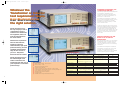
1
19998-WK 8pp 3255/3260 6/9/00 11:57 am Page 1
3260B Precision Magnetics Analyzer
3255B Inductance Analyzer
3265B 25A Bias Unit
19998-WK 8pp 3255/3260 6/9/00 11:59 am Page 2
Whatever the
Transformer or Inductor
test requirement Wayne
Kerr Electronics has
the right solution.
Completely characterize your
component graphically
At the design stage of component development
it is important to understand how the
component will perform under different test
conditions. This might include Frequency, AC
Drive Level or DC Bias Current.
The 3260B Precision Magnetics Analyzer can
plot any of the measurement functions, such as
Inductance (L) or Impedance (Z), including
secondary term, against Frequency, AC Drive
Level or DC Bias Current.
A Frequency range from 20Hz to 3MHz can be
selected and displayed linearly or logarithmically.
The selected measurement parameter and its
secondary value is presented graphically. The
AC Drive Level can be set between 1mV to 10V,
whilst the DC Bias Current, using the external
3265B unit, can produce between 1mA and
125A of Bias.
Wayne Kerr Electronics is
the only company to offer a
comprehensive range of
Inductance and Transformer
test equipment, which can
meet the requirements of
the whole market.
Measure Insertion Loss and
Return Loss on Telecom
Transformers
With the explosive growth of PC's connected to
the telephone system for Internet access has
come the requirement to measure Insertion
Loss (IL) and Return Loss (RL) of line matching
transformers.
Whatever the requirement…
telecom measurements,
graphical component
characterisation, high speed
production testing, accurate
The 3260B Precision Magnetics Analyzer has
this capability. It also allows the user to enter
the values for terminating Resistance or
Impedance, if complex, and to select a damped
network or blocking capacitor if required.
repeatable measurements,
large DC bias currents or
just cost… Wayne Kerr
Electronics has the solution.
Wayne Kerr Electronics are
the acknowledged world
leader in Inductance and
Transformer test with over 50
years experience of innovative
product design.
Products at a glance
Function
Frequency Range
Basic Accuracy
Measurement Function
3260B
20Hz - 3MHz
3255B
20Hz - 500kHz
0.1%
0.25%
Z, o, L, C, Rac, Rdc, Q, D,
Turns Ratio, Leakage L,
Interwinding C, Resonant Frequency
Z, o, L, C, Rac, Rdc, Q, D,
Turns Ratio, Resonant Frequency
-
Key Features
'Analysis' mode
Yes
●
Telecom' mode
Yes
-
'Multi Frequency' mode
Yes
Yes
●
●
●
●
●
●
●
●
●
Wide frequency range – 20Hz to 3MHz
Basic accuracy – 0.1%
Telecom measurement function
Analysis mode (Graphing)
Swept - Frequency, AC Drive Level and DC Bias Current
Comprehensive measurement functions, including leakage tests
Up to 125Amps of DC bias current
Straight forward, intuitive operation
Print test results
IEEE488 control using FREE LabVIEWTM driver
‘Sequence' mode
Yes
-
1mA – 1A (internal)
Up to 125A (using 3265B)
1mA – 1A (internal)
Up to 125A (using 3265B)
Printer Output
Yes
Yes
GPIB Interface
Yes
Yes
Up to 20 measurement/sec
Up to 20 measurement/sec
DC Bias Current
Measurement Speed
3265B
N/A
Up to 25A per unit
19998-WK 8pp 3255/3260 6/9/00 12:01 pm Page 4
Precision Magnetics Analyzer 3260B
Accuracy, Speed and a
complete range of
Measurement functions….
The right combination
MEASUREMENT
PARAMETERS
Any of the following parameters can
be measured and displayed:
Wayne Kerr Electronics provides
a full compliment of measurements, which
can test a wide range of Inductors and
Transformers. Basic measurements such as
Impedance (Z), Phase Angle (O), Inductance
(L), Capacitance (C), DC Resistance (Rdc),
AC Resistance (Rac), Quality Factor (Q) and
Dissipation Factor (D), are complemented
by advanced measurements, Turns Ratio
(TR), Primary and secondary Leakage
Inductance, Interwinding Capacitance,
Insulation Resistance, Insertion Loss (IL)
and Return Loss (RL).
Impedance mode
Inductance (L), Impedance (Z), Rdc
and Capacitance (C).
Series or parallel equivalent circuit
Loss term: Quality factor (Q),
Dissipation factor (D), Rac and angle,
Analogue scale (bargraph) with
nominal, absolute and % modes
Handler mode
Enables existing 4-wire scanners to
be used
Functions as for impedance mode
with the addition of turns ratio
Transformer mode
Rdc of each winding, Primary or
Secondary Leakage Inductance and
Q, Turns Ratio, Interwinding
Capacitance and Leakage Inductance.
Insulation between windings from
either winding to screen/core is
available as an option.
In some applications speed of
measurement is critical. The
Wayne Kerr Electronics range of
magnetic and inductance analyzers can
deliver up to 20 measurements per second
whilst maintaining measurement accuracy
and integrity.
Telecom mode
Provides derivation of Insertion Loss
(IL) and Return Loss (RL) for line
matching transformers operating in
the telephone speech band (100Hz to
20kHz). Values of line impedance (Zo)
and termination (Rt) are user
selectable. Optional simulated
damping network and series blocking
capacitor are user configurable.
In Multi-Frequency mode the user is able to
make measurements at a number of fixed
frequencies and present the results in
tabular form, and against preset limits
Test under real operating
conditions with up to 125
Amps of DC Bias Current
The 3265B DC Bias Unit provides up to
25Amps of DC bias current in steps
0.025Amps. Use five in parallel and
125Amps can be achieved. In addition both
analyzers can provide an internal DC bias
from 1mA to 1Amp. The 3265B has a
safety interlock system to protect the user
against back EMF's. The unit is also fully
protected against 'overtemperature',
'excess voltage drop' and 'sense lead
failure'.
Printed output of the
test results
Using the parallel centronics interface the user can directly print test
results including graphs for further analysis and storage. In addition, via
the IEEE488 interface the instrument can be controlled automatically
from a PC controller. LabVIEWTM drivers are available on request or via
our web site - www.waynekerrtest.com, providing a base from which a
user can develop a specific test application.
Analysis mode
Measurement parameters and test
conditions set using measurement
mode Graphical sweep vs frequency,
AC Drive Level or DC Bias Current
with selection of start, stop, step size,
units and linear/log.
Multi-Frequency mode
Measurement parameters and test
conditions set using measurement
mode. Up to 8 frequencies with
absolute or percentage limits on
major term PASS/FAIL indications.
TEST CONDITIONS
Binning function allows the user to specify up to 10 bins sorting by
either absolute or percentage terms.
Value for money from the leader in
component test
Delivering the legendary Wayne Kerr performance and considerable
functionality, Wayne Kerr component analyzers also offer excellent
value for money and will appeal to those users for whom
price/performance is of paramount importance.
Low level AC drive
For measurement of L + Q, Ls + Rs,
C, Z, Turns Ratio and Leakage
Inductance
Frequency range
20Hz to 3MHz Interwinding C
minimum frequency 1kHz
Steps
Increments of 1% or better across
range 1200 frequencies approx.
Accuracy of selected frequency
±0.01%
Drive level
Source impedance 50Ω
1mV to 10V rms into open circuit
50µA to 200mA rms into short circuit
ALC maintains level applied to DUT at
±2%, ±1mV of set voltage or
±2% ±0.1mA of set current.
DC bias current
1mA to 1A dc is available from
internal, fast settling bias supply over
full frequency range
Voltage compliance 20V minimum
Safety interlock provision
DC resistance
Low test level 100mV
Short circuit current 10mA
Insulation (option)
Test voltages of 100, 200 or 500V dc.
User selectable
Voltage accuracy ±3%
For user safety, short circuit current
is limited to <2mA
Bin Handler mode (option)
Sort to 1 of 10 bins using absolute or
percentage limits.
Separate Pass/Fail output.
Up to 100 bin limit set-ups stored in
non-volatile memory.
TTL interface to external bin handler
via 25 way D type connector.
Telecom mode (option)
Drive level - 28 to 16dBm
Test time varies with level
Zo/Rt 50 - 2000Ω
Test time < 1.5s typical
MEASUREMENT SPEEDS
For impedance, turns ratio, dc
resistance and insulation
4 speeds selectable: MAXimum,
FAST, MEDium and SLOW
MAX (25 measurements per second)
for component sorting under IEEE
488.2 remote control.
FAST Approximately 10 measurement
per second.
SLOW Approximately 1 per second
for increased stability and accuracy
MEASUREMENT
RANGES
R 0.01mΩ to >2GΩ*
L 0.1nH to >1000H*
C 5fF to >1F*
ACCURACY
Inductance/Rac/Z/Cp ±0.1%**
Q ±0.1% (Q+1/Q)**
D ±0.001 (1+D2)**
Turns ratio ±0.1%**
Rdc ±0.5%
Insulation ±5% (500V test)
Insertion Loss±0.1dB
Return Loss±1dB
Basic accuracy varies with frequency,
Zo, Rt, range and level.
* Varies with measurement speed
** Varies with frequency and option chosen
Specification
GENERAL DATA
Input specification
Power supply
230V AC ±10% or
115V AC ±10% (selectable)
50 to 400Hz
400 VA maximum consumption
Display
High contrast monochrome LCD
320 x 240 dot with CFL back lighting.
Visible area 115 x 86mm.
Viewing angle 45˚
Measurement connections
8 front panel BNC sockets
2- or 4-wire (Kelvin) measurements
Equivalent circuit symbols on screen
Separate terminals for primary and
secondary connections LEDs indicate
active terminals
Remote control (option)
Conforms to GPIB (IEEE-488.2)
and SCPI 1992.0
Printer output
Centronics/parallel printer port
Ambient conditions
Operating temperature range 0˚C to
40˚C. Full Accuracy 15˚C to 35˚C
Safety
Complies with the requirements of
EN61010-1
EMC
Complies with EN50081-1,
EN50082-1 generic emissions and
immunity standards by meeting with
the requirements of EN55022,
IEC801.2, IEC801.3 and IEC801.4
Mechanical (approx. overall)
Height 150mm (6“)
Width 440mm (17 3⁄8“)
Depth 520mm (20 1⁄2“)
Weight 11kg (24lbs 4oz.)
ORDER CODES/OPTIONS
IJ3260B
Precision Magnetics Analyzer
Supplied with User Manual, power
cable, spare fuses, safety interlock jack
Options
/N Insulation resistance test
/G Analysis function (graphs)
/T LF Telecom function
/D Binning function
Accessories
1EXA20230
Rack mounting kit. 3U x full width
1EVA40100
Kelvin clips (fine jaws).
2 sets recommended for transformer
tests
1EVA40180
Kelvin clips (large jaws)
1EV1006
BNC to 4-terminal component fixture.
Recommended above 500kHz
1EV1505
4-terminal lead set.
2 set recommended for power
transformers tests
A40120
SMD Tweezers
19998-WK 8pp 3255/3260 6/9/00 12:03 pm Page 6
Inductance Analyzer 3255B
MEASUREMENT
PARAMETERS
Any of the following parameters can
be measured and displayed:
Impedance mode
Inductance (L), Impedance (Z), Rdc
and Capacitance (C).
Series or parallel equivalent circuit
Loss term: Quality factor (Q),
Dissipation factor (D), Rac and angle,
Turns Ratio
% difference mode and relative mode
on major terms
Multi-Frequency mode
Measurement parameters and test
conditions set using measurement
mode. Up to 8 frequencies with
absolute or percentage limits on
major term PASS/FAIL indications.
TEST CONDITIONS
Low level AC drive
For measurement of L + Q, Ls + Rs,
C, Z, Turns Ratio
Frequency range
20Hz to 500kHz
Steps
Independent settings are available for
different tests. At least 800
frequencies, which may be selected
via keyboard or GPIB
Basic accuracy of selected
frequency ±0.01%
Drive level
Source impedance 50Ω
1mV to 10V rms into open circuit
50µA to 200mA rms into short circuit
ALC ensures level at DUT is
±2%, ±1mV of set voltage or
±2% ±0.1mA of set current,
reduces to ±4% below 100Hz
DC bias current (Option)
1mA to 1A dc is available from
internal, fast settling bias supply over
full frequency range
Voltage compliance 14V minimum
DC Accuracy 2% ±0.25 mA
Enabling DC bias inherently
reduces measurement accuracy.
Safety interlock
DC resistance
Low test level 100mV
Short circuit current 10mA
Bin handler mode (option)
Sort to 1 to 10 bins using absolute or
percentage limits.
Separate Pass/Fail output.
Up to 100 bin limit set-ups stored in
non-volatile memory.
TTL interface to external bin handler
via 25 way D type connector
MEASUREMENT SPEEDS
For impedance, turns ratio, dc
resistance
4 speeds selectable for all functions:
MAXimum, FAST, MEDium and
SLOW. Maximum for remote control.
Up to 20 measurements per
second for test frequency
≥100Hz. Selecting slower speeds
improves accuracy and display
resolution
MEASUREMENT
RANGES
L 1nH to 1000H
Z 0.05m to >2MΩ
C 0.01pF to >250mF
Rdc 0.5mΩ to 50kΩ
Turns Ratio 100:1 to 1:100
ACCURACY
L/C/Z/Turns Ratio ±0.25%
Q ±0.25% (Q+1/Q)
D ±0.0025 (1+D2)
Rdc ±0.5% ±1m0hm
Note: Ranges and accuracy vary with
measurement speed, frequency and
options chosen
GENERAL DATA
Input specification
Input voltage
230V AC ±10% or 115V AC ±10%
(selectable)
Frequency 50/60 Hz
VA rating 150VA
Input fuse rating
230V operation - 1A “T” type
115V operation - 2A “T” type
Display
High contrast black and white LCD
module 320 x 240 dot with CFL back
lighting. Visible area 115 x 86mm.
Viewing angle 45˚
Measurement connections
4 front panel BNC sockets
4-wire (Kelvin) measurements with
screen at ground potential.
Equivalent circuit symbols on screen
DC Bias Unit 3265B Specification
Specification
Storage -40˚C to +70˚C
Operating 0˚C to 40˚C
Full Accuracy 15˚C to 35˚C
Altitude up to 2000m
Relative humidity: up to 80%
non-condensing
Installation category: II (in
accordance with IEC664)
Pollution degree: 2 (mainly nonconductive)
This equipment is intended for indoor
use only in non-explosive, noncorrosive atmosphere
SAFETY
Complies with the requirements of
EN61010-1
EMC
Complies with EN50081-1,
EN50082-1 generic emissions and
immunity standards by meeting with
the requirements of EN55022,
IEC801.2, IEC801.3 and IEC801.4
Mechanical (approx. overall)
Height 150mm (6“)
Width 440mm (17 3⁄8“)
Depth 520mm (20 1⁄2“)
Weight 11kg (24lbs 4oz.)
Summary specification. A full
specification is available on request
ORDER CODES/OPTIONS
1J3255B
Inductance Analyzer (20 Hz - 500 kHz)
Supplied with User Manual and 2m
AC power cable
Description
Dimensions
25A DC bias unit
Maximum compliance voltage
(<12kHz). 11Vdc (at 0.25Vac drive
level). 10V compliance at 1 Vac drive
level. Where f>12Khz deduct 0.5V.
Must be used in conjunction with
either a 3260B or 3255B
Height 190mm (7 1⁄2“)
Width 440mm (17 3⁄8“)
Depth 520mm (20 1⁄2“)
Weight 15kg (33lbs)
Applications
Permits measurement analysis of
wound components with levels of DC
bias current higher than the standard
1A
Variable measured
In impedance mode: L, Z, R, Q, D.
Not applicable to Rdc, or transformer
measurements
Measured frequency range
3255B 20Hz to 500kHz
3260B 20Hz to 1 MHz
Basic accuracy
± 1%
Varies with measurement speed.
Varies with frequency and option chosen.
Measurement terminals
2-terminals measurement via M8
studs. 4-terminal measurement via
Kelvin leads and M8 studs.
Measurement terminals internally
protected by 1.6A fuses against
normal inductor back-EMF or
accidental disconnection of inductor.
Front panel fuses easily replaced
Control connections
1 C bus link controls application of DC
current and monitors status of
analyzer. Status data includes
'excessive voltage drop' and
'overtemperature'
2
Optional facilities
3265B bias units may be paralleled.
Maximum 5 units giving 125A
Options
/A 1 mA - 1 A Internal DC Bias
/B IEEE-488 interface
/D Binning function
Interlock
Bias safety interlock socket on rear
panel of analyzer provides door lock
and closed control lines
Accessories
Temperature range
1EVA40100
Kelvin clips (fine jaws). Recommended
Storage: -40˚C to + 70˚C
Operating: 0˚C to + 40˚C (20A max)
Full accuracy: 15˚C to + 30˚C (25A
max)
1EV1505
4-terminal lead set.
Power supply
Printer output
Centronics/parallel printer port
1EVA40180
Kelvin clips (large jaws)
Remote control (Option)
Designed to GPIB (IEEE-488.2)
and SCPI 1992.0
Environmental conditions
A40120
SMD tweezers
Temperature range
1EXA20230
Rack mounting kit. 3U x full width
Universal 90 to 255V ac
47 to 63Hz
Input current 9A rms max.
Power factor >0.9
Unit powers up automatically when
connected to a powered analyzer
Isolating switch provided
Cooling
Fan cooled. Intake front, exhaust rear.
Fan filter accessible on front panel.
Overtemperature trip provided
ORDER CODE
IJ3265B
25A DC bias unit 3265B
Supplied with User Manual, power
cable, spare fuses, 4 x BNC to BNC
links, daisy chain link, rack mounting
ears (unit needs rear support) and
bus bars.
Accessories
1EVA40100
Kelvin clips leads (fine jaws).
1EVA40180
Kelvin clips leads (large jaws)
4-324-6009
Power transfer bus bars
(2 each per unit in parallel)
HMDEC10
Filter pad (washable)
19998-WK 8pp 3255/3260 6/9/00 12:05 pm Page 8
USA
UK
GERMANY
Wayne Kerr
11 Sixth Road
Woburn MA 01801-1744
Durban Road Bognor Regis
West Sussex PO22 9RL
Hitek Power GmbH
Gutenbergring 5
D-63110 Rodgau, Germany
Tel: 781 938 8390
Fax: 781 933 9523
Sales: (800) 933 9319
email: [email protected]
Tel: +44 1243 825811
Fax: +44 1243 824698
email: [email protected]
www.waynekerrtest.com
Distributors worldwide contact UK office
Tel: +49 06106 7080 30
Fax: +49 06106 7080 40
email: [email protected]