1
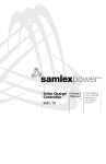
Remote
Control for
Inverter
RC-200
Owner's
Manual
Please read this
manual before
operating your
RC-200 Remote
Control
Owner's Manual | Index
SECTION 1
Safety ......................................................................................3
SECTION 2
Description
....................................................................................3
SECTION 3
Layout of Controls, Indications
& Dimensional Drawings ................................................................... 3
SECTION 4
Installation ......................................................................................6
SECTION 5
Operation .....................................................................................6
SECTION 6
Specifications......................................................................................6
SECTION 7
Warranty
......................................................................................7
DETAILED PRODUCT INFORMATION
For a complete user manual including specifications, application notes,
installation instructions, trouble shooting and more, please visit the
web page for this product on samlexamerica.com. Product page can
be found using the “search by model” field.
2 | SAMLEX AMERICA INC.
SECTION 1: SAFETY
Before using this Remote Control, please follow the Safety Instructions given in
the Owner’s Manual for the inverter.
SECTION 2 | DESCRIPTION
RC-200 is a wired Remote Control that is compatible with the following series
of Inverters: PST-1500-12, PST-1500-24; and PST-2000-12, PST-2000-24.
It is used to switch ON and switch OFF the inverter from a remote location. It
also displays the operational status using LCD display and colored LEDs. It is
provided with 5 Metres / 16.5 Feet of connecting cable set with RJ-50 Modular
Plugs (10P10C). The conductors of the cable set have crossed-over (rolled-over)
connections on the two RJ-50 plugs.
SECTION 3 | LAYOUT OF CONTROLS, INDICATIONS
& DIMENSIONAL DRAWING
Fig. 1 (page 4) shows the layout of controls and indications and dimensional
drawing.
ON/OFF Control
ON/OFF Push Button (1) is used to switch ON and switch OFF the inverter. Every
time the ON/OFF Push Button is pressed, a beep will be heard.
LCD Display
LCD screen (3) is used to display the following 6 output parameters in a sequential loop as given below.
The screen changes to show the successive parameter in a sequential
manner every time the “Display Push Button” (2) is pressed (Sequence is:
Screen1-2-3-4-5-6-1-2-3…)
1.
2.
3.
4.
5.
6.
AC output voltage in Volts, V
AC output current in Amps, A
AC output frequency in Hertz, Hz
Active AC output power in Watts, W - The display is limited to a
range of 2.5W - 3500W
Apparent Output Power in Volt Amps, VA
Power Factor, PF
When the inverter is switched ON using the ON/OFF Push Button (1), the LCD
screen displays information as follows:
•
•
•
It takes 2 to 6 sec for booting / initialization. During this time, all the above
6 parameters will be displayed as “0”
If the load is > 2.5W, all the above 6 parameters will be available for display after
end of booting / initialization period
If the AC output power is less than 2.5W, parameters “AC output current in A”,
“Active AC output power in Watts, W”, “Apparent Output AC Power in Volt
SAMLEX AMERICA INC. | 3
Amps, VA” and “Power Factor, PF” will not be displayed (will be displayed as “0”).
This is necessary because at power output < 2.5W, the noise on the output side
may be comparable to the low value of the load and the logic may not be able
to differentiate noise from load and hence, may display wrong values for these
parameters
Power Saving / Sleep Mode in the LCD Display
To save power, the LCD display will remain ON for 3 minutes from the time the
Display Push Button (2) is pressed and will then switch OFF into Sleep Mode. To
wake up, press the Display Push Button (2).
2
3
65
DISPLAY
4
Pure
Sine Wave
OVER
LOAD
MODEL RC-200
OVER
TEMP
POWER
5
6
1
110
Front View
Overall Depth: 25.5
1
8,5
32,5
4
R2
R2
4 32,5
48
7
32,5
32,5
98
8,5
15
80
15
Back View
LEGEND
1.
2.
3.
4.
5.
6.
7.
Power ON/OFF Push Button
Push Button to Change Display Screen
LCD Screen
LED - “Overload”
LED - “Over Temp”
LED - “Power”
RJ-50 Modular Jack
(NOTE: All dimensions in mm)
Fig. 1 Remote Control RC-200 - Layout and Dimensional Drawing
4 | SAMLEX AMERICA INC.
LED Display
The following LED displays are available:
•
Green LED (6) marked POWER. This LED will be lighted when the inverter is in ON
condition. When the inverter is in OFF condition, this LED will not be lighted. This
LED shows that DC input is available to the inverter and that the input section of the
inverter is operating normally
Red LED (4) marked OVER LOAD. When lighted, it indicates that the AC output of the
inverter has been shut down due to over load
Red LED (5) marked OVER TEMP. When lighted, it indicates that the AC output of the
inverter has been shut down due to over temperature
•
•
Pinout of Rj-50 Modular Jack
The pinout of the RJ-50 Modular Jack (7) at the back of the unit is given at Fig.
2 below:
LEGEND
1 2 3 4 5 6 7 8 9 10
1.
2.
3.
4.
5.
6.
7.
8.
9.
10.
Toggle
Avcc
Ground for LEDs
Vcc
LED - “Power ON”
LED - “Over Temp”
LED - “Over Load”
LCD - Light
LCD - Data
LCD - Ground
Fig. 2 Remote Control RC-200 - Pinout of Modular Jack RJ-50
The standard numbering system of the pins of a Modular Jack, when looking into
the Jack, is from left to right. As the conductors of the cable are cross-connected
(rolled-over), the pinouts at the Modular Jack in the inverter will be a mirror image
Figure 2 Remote Control RC-200; Pintout of Modular Jack RJ-50
of the pinout of the
Modular Jack in the Remote Control as shown in table below:
Pinout of Modular Jack on
the Remote Control1
Signal
Pinout of Modular
Jack on the inverter2
1
Toggle
10
2
Avcc
9
3
Ground for LEDs
8
4
Vcc
7
5
LED - “POWER ON”
6
6
LED - “OVER TEMP”
5
7
LED - “OVER LOAD”
4
8
LCD - Light
3
9
LCD - Data
2
10
LCD - Ground
1
1. As shown in Figure 2
2. Mirror image of Remote Control Jack due to crossed-over /rolled over connection of conductors.
SAMLEX AMERICA INC. | 5
SECTION 4 | INSTALLATION
Please refer to Fig. 1. The Remote Control can be flush mounted on a wall or a
panel by making a suitable cut-out to accommodate the projection in the back.
Connect one end of the cable set to the RJ-50 Modular Jack (7) at the back and
the Remote and the other end to the RJ-50 Modular Jack on the inverter. Ensure
that the connection is firm and the tab on the plug securely locks in the jack.
SECTION 5 | OPERATION
Please refer to Fig 1. Please also refer to the Owner’s Manual of the inverter
for associated details. NOTE: For the Remote Control to operate, the ON/OFF Switch
on the inverter is required to be in ON condition to activate the control circuitry for the
Remote Control. Switch on the inverter first with the help of the Power ON/OFF Switch on
the inverter. The output of the inverter can now be switched OFF/ON by pressing the ON/
OFF Push Button (1).
See under headings “LCD Display” and “LED Display” above for information
on the operating conditions. Read the Owner’s Manual of the inverter for
troubleshooting of abnormal conditions indicated by the LEDs.
No Load Current Draw
As stated above, the ON/OFF Switch on the inverter is required to be in ON
condition for the Remote to operate. When the ON/OFF switch on the Remote
Control is turned ON, all the circuitry inside the inverter becomes fully alive and
the AC output is made available. In this condition, even when no load is being
supplied (or, if a load is connected but has been switched OFF), the inverter
draws a small amount of current from the batteries to keep the circuitry alive
and is ready to deliver the required power on demand. This is called the “idle
current” or the “no load current draw”. When the inverter is turned OFF using
this Remote Control, some control circuitry is still alive in the inverter and will
require very small current draw. Hence, when the load is not required to be
operated, turn OFF the ON/OFF Switch on the inverter to prevent unnecessary
current drain from the battery.
SECTION 6 | SPECIFICATIONS
Model Numbers of
compatible Inverters
PST-1500-12, PST-1500-24
PST-2000-12, PST-2000-24
Cable Set
RJ-50 (10P10C) with crossed-over / rolledover connections. Length = 5 metres /16.5'
Operating Temperature Range
0 to 40°C / 32°F to 104°F
Dimensions (L x W x D)
110 x 65 x 24.7 mm / 4.33 x 2.56 x 0.97 in
Weight (Without cable / with cable)
6
| SAMLEX AMERICA INC.
85 gm / 256 gm; 0.04 lb / 0.12 lb
NOTE: Specifications are subject to change without notice
SECTION 7 | WARRANTY
2 Year limited warranty
RC-200 Remote Control manufactured by Samlex America, Inc. (the
“Warrantor“) is warranted to be free from defects in workmanship and
materials under normal use and service. The warranty period is 2 years for the
United States and Canada, and is in effect from the date of purchase by the
user (the “Purchaser“).
Warranty outside of the United States and Canada is limited to 6 months. For a
warranty claim, the Purchaser should contact the place of purchase to obtain a
Return Authorization Number.
The defective part or unit should be returned at the Purchaser’s expense to the
authorized location. A written statement describing the nature of the defect,
the date of purchase, the place of purchase, and the Purchaser’s name, address
and telephone number should also be included.
If upon the Warrantor’s examination, the defect proves to be the result of
defective material or workmanship, the equipment will be repaired or replaced
at the Warrantor’s option without charge, and returned to the Purchaser at
the Warrantor’s expense. (Contiguous US and Canada only)
No refund of the purchase price will be granted to the Purchaser, unless the
Warrantor is unable to remedy the defect after having a reasonable number
of opportunities to do so. Warranty service shall be performed only by the
Warrantor. Any attempt to remedy the defect by anyone other than the
Warrantor shall render this warranty void. There shall be no warranty for
defects or damages caused by faulty installation or hook-up, abuse or misuse
of the equipment including exposure to excessive heat, salt or fresh water
spray, or water immersion.
No other express warranty is hereby given and there are no warranties which
extend beyond those described herein. This warranty is expressly in lieu of
any other expressed or implied warranties, including any implied warranty of
merchantability, fitness for the ordinary purposes for which such goods are
used, or fitness for a particular purpose, or any other obligations on the part of
the Warrantor or its employees and representatives.
There shall be no responsibility or liability whatsoever on the part of the
Warrantor or its employees and representatives for injury to any persons, or
damage to person or persons, or damage to property, or loss of income or
profit, or any other consequential or resulting damage which may be claimed
to have been incurred through the use or sale of the equipment, including
any possible failure of malfunction of the equipment, or part thereof. The
Warrantor assumes no liability for incidental or consequential damages of any
kind.
Samlex America Inc. (the “Warrantor”)
www.samlexamerica.com
SAMLEX AMERICA INC. | 7
Contact
Information
Toll Free Numbers
Ph: 800 561 5885
Fax: 888 814 5210
Local Numbers
Ph: 604 525 3836
Fax: 604 525 5221
Website
www.samlexamerica.com
USA Shipping Warehouse
Kent WA
Canadian Shipping Warehouse
Delta BC
Email purchase orders to
[email protected]
11001-RC-200-1112