1
LTPP Manual for Profile Measurements, Version 4.0, September 2002
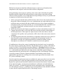
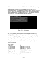
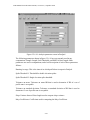
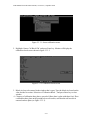
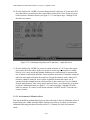
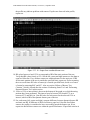
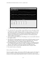
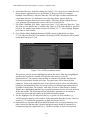
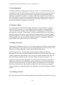
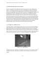
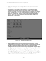
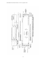
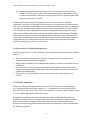
part of the screen. This message indicates the MDR program has successfully linked up
with the WinGraph program. The values shown for POS1, POS2, POS3, SEN1, SEN2,
SEN3 and filename on the monitor will be different from the values for these parameters
shown in figure 2.3.4.10. Path and filename that are shown will be path and file name that
were typed in steps 6 and 7 of section 2.3.4.1.
Figure 2.3.4.10. MDR run screen.
4. Driver should attain a constant test speed of 80 km/h at least 175 m before beginning of
test section and align vehicle along wheel paths. (As described in section 2.2.7.4, a speed
different from 80 km/h may be used depending on site conditions). Then press F3 key to
start the DMI about 150 m before the start of the test section. (Note: The profiler should
have attained its testing speed prior to pressing the F3 key).
5. About 40 m before start of the section (after passing lead-in stripe of the section), press
F6 key. When F6 key is pressed, asterisk beside the 0 in section field will disappear.
When F6 key is pressed, the photocell is armed and will be looking for reflective mark
on pavement surface or cone with reflective marking (depending on photocell that was
selected) to record an event mark and perform a reference reset.
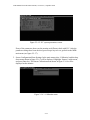
6. When photocell detects target, green part of screen will show the message ‘Reference
Reset’, and a beep will be heard. If photocell is not triggered when event mark is passed,
clean photocell and repeat run and see if the photocell triggers. If the photocell still fails
to trigger, operator should adjust threshold control for photocell using procedures
described in Section 19 of the ICC Road Profiler Operation Manual (1) and see if
photocell will trigger. If this is not successful, operator should use horizontal photocell.
Follow procedure described in step 3 of section 2.3.4.1 to select horizontal photocell to
2-62