1
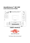
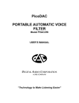
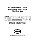
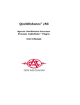
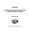
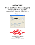
QuickEnhance™ QE-10
Speech Enhancement Processor
USER'S MANUAL
Digital Audio Corporation
"Technology to Make Listening Easier"
QuickEnhance™ QE-10
Speech Enhancement Processor
USER'S MANUAL
Document Number 020610AME
June 10, 2002
Digital Audio Corporation
4018 Patriot Drive
Suite 300
Durham, NC 27703
Phone: 919.572.6767
Fax: 919.572.6786
Web: www.dacaudio.com
Email: [email protected]
Copyright © 2002 by Digital Audio Corporation.
All rights reserved.
Table of Contents
CHAPTER 1: INTRODUCTION .......................................................................4
CHAPTER 2: SETUP AND CONNECTIONS .................................................5
2.1 DC Input ..............................................................................................5
2.2 Printer Port ..........................................................................................5
2.3 Digital Audio Interfaces .....................................................................5
2.4 Analog Audio Interface ......................................................................6
CHAPTER 3: INPUT SECTION .......................................................................7
3.1 Input Select Switches ..........................................................................7
3.2 Input Levels .........................................................................................8
CHAPTER 4: AUDIO ENHANCEMENT MODULES ...................................9
4.1 Master Switch ......................................................................................9
4.2 Hum Filter Module ...........................................................................10
4.3 Deconvolver Module .........................................................................11
4.4 Noise Reduction Module ...................................................................12
4.5 Graphic Equalizer Module ...............................................................12
4.6 Automatic Gain Module ...................................................................13
CHAPTER 5: OUTPUT SECTION .................................................................14
5.1 Headphones .......................................................................................14
5.2 Report Button ....................................................................................15
5.3 Power Switch .....................................................................................15
CHAPTER 6: SPECIFICATIONS ...................................................................16
2
Table of Figures and Tables
Figure 1 – QE-10 Rear Panel ...............................................................................5
Figure 2 – QE-10 Input Section ...........................................................................7
Figure 3 – MASTER IN/OUT Switch .................................................................9
Figure 4 – HUM FILTER Module ....................................................................10
Figure 5 – DECONVOLVER Module ...............................................................10
Figure 6 – NOISE REDUCTION Module ........................................................12
Figure 7 – GRAPHIC EQUALIZER Module ..................................................12
Figure 8 – AUTOMATIC GAIN Module .........................................................13
Figure 9 – QE-10 Output Section ......................................................................14
Table 1 – DECONVOLVER Mode Selections ..................................................11
3
CHAPTER 1:
INTRODUCTION
Thank you for purchasing the QuickEnhance™ QE-10 Speech Enhancement Processor.
We hope you will find this product the breakthrough in power, ease-of-use and value that
we intended it to be.
Please take a few moments to read this User’s Guide to familiarize yourself with the
main features and functions of the QE-10. If you are new to audio enhancement, pay
particular attention to Chapter 4: Audio Enhancement Processors, which details the
operation and recommended usage of the vast processing resources the QE-10 has to
offer.
Enjoy using your new QE-10!
4
CHAPTER 2:
SETUP AND CONNECTIONS
The QuickEnhance™ QE-10 has numerous ways to connect to common laboratory audio
equipment, including two digital audio interfaces and one analog audio interface. This section
details the type and purpose of the various rear panel connectors.
Figure 1 - QE-10 Rear Panel
2.1
DC POWER
A 2.1mm barrel-type DC POWER connector (See Figure 1) with positive tip is provided for
supplying power to the unit. An external universal AC adapter with line cord is included in the
package. The unit can accept DC power input at a range of 9–18V and draws a maximum peak
current of 4A.
2.2
PRINTER PORT
The standard 25-pin parallel PRINTER PORT (See Figure 1) is provided to implement the
printed REPORT feature for forensic documentation of front panel settings (See Section 5.2 Report Button). The PRINTER PORT is suitable for connection to most inkjet, dot matrix, and
laser printers that support ASCII text printing.
2.3
DIGITAL AUDIO INTERFACES
There are two types of DIGITAL audio interfaces provided on the QE-10: S/PDIF on coaxial
(RCA) connectors and optical digital on TOSLINK connectors (See Figure 1). Both interfaces
support input of stereo 24-bit digital audio signals at a maximum sampling rate of 96kHz. These
digital interfaces are commonly found on professional and some consumer audio equipment such
as CD players, MiniDisc players, DAT machines, PC sound cards, etc. Only one of the digital
audio inputs can be active at a time, (See Section 3.1 - Input Select Switches) but both digital
audio outputs are always active. The digital outputs’ sampling rate is always 44.1kHz, regardless
of the sample rate of the digital input; this is made possible by the high-quality real time sample
rate conversion in the QE-10.
5
2.4
ANALOG AUDIO INTERFACE
Unbalanced stereo ANALOG inputs and outputs (See Figure 1) are provided on standard RCA
connectors. The ANALOG inputs are capable of accepting line level signals up to 3.0Vrms and
have an input impedance of 25kΩ. The ANALOG outputs have a maximum level of 3.0Vrms at
full scale and the output impedance is 100Ω. The ANALOG inputs are only active when selected
with the front panel INPUT SELECT switches (See Section 3.1 - Input Select Switches) but the
outputs are always active.
6
CHAPTER 3:
INPUT SECTION
The input section of the QuickEnhance™ QE-10 is the place where the desired input source is
selected and the audio input levels are set and monitored.
Figure 2 - QE-10 Input Section
3.1
INPUT SELECT SWITCHES
There are three possible input sources to the QE-10 audio processor, one analog and two digital.
(See Sections 2.3 - Digital Audio Interfaces and 2.4 - Analog Audio Interface) The INPUT
SELECT and DIGITAL INPUT switches (See Figure 2) are used to select which one of these
three sources is routed through the QE-10’s audio processor. With the INPUT SELECT switch in
the ANALOG position, the signal connected to the unbalanced RCA analog inputs is selected.
When this switch is in the DIGITAL position, the DIGITAL INPUT switch determines whether
the COAXIAL or TOSLINK digital input is selected. This switch has no function when the
INPUT SELECT switch is in the ANALOG position.
Note: The INPUT SELECT switches only affect the routing of signals into the QE-10. All three
outputs are always active and available regardless of the position of these switches. In this way,
the QE-10 can function as an audio patchbay, converting any of the three input types to any output.
7
3.2
INPUT LEVELS
The two INPUT LEVEL knobs (See Figure 2) allow the user to add gain to a low-level signal to
bring it up to a normal processing level, or to attenuate a loud signal that may be overloading the
input circuitry of the QE-10. The center detent position of the knobs indicates the 0 dB point
where no gain or attenuation is applied to the input signal. These INPUT LEVEL knobs work the
same regardless of the type of input selected. (See Section 3.1 - Input Select Switches)
The input signal strength can be monitored using the LED bargraph display (See Figure 2). This
display is calibrated in units of decibels (dB) below full scale. In other words, a signal having
peaks that illuminate the –18 segment of the bargraph display is 18 decibels below the maximum
possible signal level into the QE-10. A normal processing level will cause the peaks of the input
signal to illuminate the yellow segments of the display without illuminating the red overload (OL)
segments. If the input signal is too strong, causing the OL indicators to illuminate, rotate the
INPUT LEVEL knobs to the left to attenuate the input signal. If the input signal is too weak,
causing none of the yellow segments to illuminate, rotate the INPUT LEVEL knobs to the right,
slowly, to add gain to the input signal.
Note: Be wary of sudden loud sounds in the input signal, such as door slams, gun shots, etc.,
which may cause the input circuitry of the QE-10 to overload. This condition is highly unpleasant
to listen to and may cause hearing damage if the listening volume is set too high. (See Section 4.1
- Headphones)
8
CHAPTER 4:
AUDIO ENHANCEMENT MODULES
Once the input source has been selected and the correct input level set, the signal passes on to the
audio enhancement signal processing section of the QuickEnhance™ QE-10. The processing
modules in the enhancement section provide the main functionality of the QE-10. Each of the
modules is designed to remove specific types of noises and the modules can be used in various
combinations to enhance audio with multiple noise problems.
The signal flows through the processing section of the QE-10 in the same order as the modules
appear on the front panel of the unit, reading left-to-right, top-to-bottom: HUM FILTER,
DECONVOLVER, NOISE REDUCTION, GRAPHIC EQUALIZER, and AUTO GAIN. The
following sections describe these modules in detail, explain the user interface controls for each,
and provide examples of common noise problems that may be improved by the use of the various
modules.
Figure 3 - MASTER IN/OUT Switch
4.1
MASTER SWITCH
The MASTER IN/OUT switch (See Figure 3) is not a processing module per se, but is used to
enable or bypass the entire signal processing section of the QE-10. When the MASTER switch is
in the IN position, the QE-10 processes the selected input signal according to the settings of the
various processing modules, and passes the result to the audio outputs and headphone circuitry.
Conversely, when the MASTER switch is in the OUT position, audio from the selected input
signal is passed directly through to the audio outputs and headphone circuitry, bypassing all
processing. It is handy to use this switch to quickly compare the processed audio with the original
unprocessed audio, to determine the effect the QE-10 is having on speech intelligibility.
9
Figure 4 - HUM FILTER Module
4.2
HUM FILTER MODULE
The HUM FILTER processing module (See Figure 4) is useful for removing hum and buzz noises
from the audio signal. A typical source of hum noise is electrical AC power. This hum may be
caused by the proximity of the recorder, microphone or microphone cables to AC-powered
electrical sources such as fluorescent lighting, power cords, motors, home electrical wiring, etc.
This noise is generally characterized by a strong energy component at either 50 Hz or 60 Hz,
(depending on the power generation standard of the particular country the recording is made in)
along with decreasing energy components at integer multiples of the base frequency.
With the ADJUST knob at the center detent position, move the HUM FILTER slide switch from
the OUT position to either the 50 Hz or 60 Hz position to activate the HUM FILTER. In doing
so, you may find that the base frequency of the hum does not fall at exactly 50 or 60 Hz, resulting
in incomplete cancellation of the hum. For example, if the recording was originally made on a
battery-powered analog tape recorder and the batteries were approaching the end of their useful
life, the recorder may have been running too slowly. When the recording is played back on a tape
player with fresh batteries or an AC power source, the recording will appear to be running faster
than normal, causing the hum component to appear at a higher frequency than 50 or 60 Hz. To
handle situations like this, the HUM FILTER base frequency can be tuned +/- 10% via the
ADJUST knob. In other words, for a base frequency of 50 Hz, the HUM FILTER can be tuned
in the range of 45 to 55 Hz, and for a base frequency of 60 Hz, a range of 54 to 66 Hz is possible.
To bypass the HUM FILTER stage so that it has no effect on the audio, move the base frequency
slider back to the OUT position.
Figure 5 - DECONVOLVER Module
10
4.3
DECONVOLVER MODULE
The DECONVOLVER processing block (See Figure 5) is designed to automatically adjust itself
to remove noises that are time-correlated from the input signal. There are two main classes of
time-correlated noises that the DECONVOLVER can remove: periodic (repeating) sounds, such
as tones, hums, engine idling sounds, electrical motors, etc.; and convolutional distortion, such as
echo, reverberation, and acoustic resonances caused by reflected sound in the environment the
recording was made in.
There are three user controls in the DECONVOLVER module. The CLEAR button is used to
flush and re-initialize the DECONVOLVER. You may wish to do this whenever the signal you
are processing has changed significantly and you want the DECONVOLVER to re-acquire a fresh
solution. In very rare instances, sudden jumps in the amplitude of the input signal may cause the
DECONVOLVER module to become unstable, resulting in static or harsh distortion at the output.
If this happens, simply press the CLEAR button to correct this condition. If the module continues
to “crash” in this way, it may be necessary to lower the input levels, or to move the
COMPLEX/NORMAL/SIMPLE slider to a different position to mitigate the problem. This
behavior does not represent a defect in the QE-10, but is an unavoidable side effect of the very
powerful signal processing taking place inside the DECONVOLVER module.
The ADAPT/FREEZE/OUT switch is used to control whether the DECONVOLVER is actively
adapting to the input signal, freezing the current solution while ignoring changes in the input
signal, or not affecting the audio signal at all. Depending on the type and nature of the noise
problem you are trying to remove and the underlying signal of interest, you may wish to allow the
DECONVOLVER to continuously ADAPT through the entire recording, or you may wish to
“train” the module on a short portion of audio, FREEZE the solution and apply that solution to the
entire recording. On difficult material, you may need to try various approaches to see which
technique yields the best result.
The COMPLEX/NORMAL/SIMPLE mode switch allows the user to modify various parameters
in the DECONVOLVER algorithm to better adapt to and remove the current noise problem. The
table below gives examples of the types of noise problems that are helped by each of the three
settings. With this in mind, however, you should always experiment with different settings to
determine the optimum position for your particular enhancement situation.
Mode
Simple
Normal
Complex
Example Usage
Removal of simple periodic noises such as tones, and for the cancellation
of minor echo, reverberation and resonances in small rooms.
Removal of more complex periodic noises such as buzzes, hums, idling
engines, etc., and for the cancellation of echo, reverberation and
resonances in recordings made in small- to medium-sized rooms.
Removal of significant echo, reverberation and resonances in recordings
made in medium- to large-sized rooms.
Table 1: DECONVOLVER Mode Selections
11
Figure 6 - NOISE REDUCTION Module
4.4
NOISE REDUCTION MODULE
The NOISE REDUCTION module (See Figure 6), unlike the DECONVOLVER, is useful for
removing noises that are not time-correlated, but are more random and unpredictable in nature.
Examples of this type of noise are air conditioner sounds, wind noises, radio static, tape hiss, etc.
Move the NOISE REDUCTION slide switch to the IN position to enable this module.
The amount of attenuation the NOISE REDUCTION module applies to the random component in
the audio signal is controlled by the ATTENUATION knob. When the knob is rotated to the
MIN position, no noise attenuation is applied to the signal. As the knob is rotated toward the
MAX position, more and more noise is removed from the audio signal. Careful adjustment of this
control is necessary to find the optimum position that causes the greatest amount of noise to be
removed without removing any desired speech components.
Figure 7 - GRAPHIC EQUALIZER Module
4.5
GRAPHIC EQUALIZER MODULE
The GRAPHIC EQUALIZER module (See Figure 7) is used to modify the tonal balance of the
audio signal. The signal is divided in frequency into ten bands, spread roughly evenly through the
portion of the frequency spectrum that human speech occupies. Ten sliders, one per band, are used
to attenuate signal energy in each band independently of the others. Slider bars are positioned at
500, 1000, 1500, 2000, 2600, 3300, 4000, 4800, 5650, and 6500 Hz. The lower a particular slider
bar is moved, the more attenuation is applied. Up to 36 dB of attenuation can be applied per band.
Move the IN/OUT slide switch to the IN position to enable the GRAPHIC EQUALIZER
module. To reduce the high frequency components in the audio signal, such as tape hiss, the rightmost sliders may be moved down. To reduce low frequency components, such as low rumble, the
12
left-most sliders may be moved down. Frequency bands that you do not wish to modify should be
left at the top (0 dB) position.
Note: Moving the IN/OUT slide switch to the IN position causes a fixed, 300 Hz high-pass filter
to be inserted into the signal path. This filter will remove any low frequencies which do not
contain useful speech information and which may be limiting the intelligibility of speech signals in
the recording.
Figure 8 - AUTOMATIC GAIN Module
4.6
AUTOMATIC GAIN MODULE
The AUTOMATIC GAIN module (See Figure 8) is a dynamic audio level processor which can
be applied to the final output of the processing stage of the QE-10. The AUTO GAIN
automatically increases the level of low-amplitude audio signals as needed to maintain a good
audio level at the output. Move the IN/OUT switch to the IN position to enable the AUTO GAIN
module. The AUTO GAIN module will apply gain as needed to maintain a good audio level up to
a maximum amount specified by the Max Gain slide switch. Three Max Gain selections are
available, 10 dB, 20 dB and 30 dB. If the signal input to the AUTO GAIN is already a good
level, no gain will be applied.
This module is useful for restoring the signal level of a heavily processed audio signal. Also,
AUTO GAIN is invaluable for correcting the near party/ far party situation, in which the talker
closest to the microphone is picked up at a much higher level than the talker furthest from the
microphone. In fact, any signal that has severely fluctuating audio levels can benefit from this
module.
13
CHAPTER 5:
OUTPUT SECTION
Once the audio signal is fully processed by the QuickEnhance™ QE-10, it will be sent to the audio
outputs and headphone circuitry for listening or recording. You may also wish to make a
permanent record of the settings used to enhance a particular recording.
Figure 9 – QE-10 Output Section and Power Switch
5.1
HEADPHONES
The HEADPHONES controls (See Figure 9) on the front panel of the QE-10 give the user a
convenient way to listen to audio signals passing through the device. There are two ¼” stereo
phone jacks on the front panel that pass identical signals and are labeled 1 and 2. This is
convenient for two-person listening sessions or for training purposes. The VOLUME knob
controls the volume of signal in both HEADPHONES jacks equally.
Two MONITOR switches allow the user to select which signal is routed to the HEADPHONES.
The INPUT/OUTPUT switch routes either the currently selected INPUT source (See Section 3.1
– Input Select Switches) or the final processed OUTPUT to the HEADPHONES. The
LEFT/STEREO/RIGHT switch routes only the LEFT channel signal to both ears, the LEFT
channel to the LEFT ear and the RIGHT channel to the RIGHT ear for STEREO listening, or
the RIGHT channel to both ears. You may wish to use this control if you have a monaural signal
plugged into only one input channel of the QE-10.
Note: The position of the MONITOR switches only affects the HEADPHONES outputs and has
no effect whatsoever on the rear-panel output signals. Therefore, the user may move these
switches as desired without affecting any recording of the processed signal.
14
5.2
REPORT BUTTON
The REPORT button (See Figure 9) is used in conjunction with the PRINTER port on the rear
panel of the QE-10 (See Section 2.2 - Printer Port). When a printer capable of producing ASCII
text printouts is connected to the PRINTER port, pressing the REPORT button will cause a plaintext formatted REPORT containing the current status of all front panel processing settings to
print. There is a provision on the printed REPORT for the user to enter the name of the examiner,
the date and time, the case number and other relevant information. This REPORT can be used to
fully restore a specific configuration of the QE-10 if needed.
5.3
POWER SWITCH
Use the POWER switch (See Figure 9) to turn the QE-10 on and off.
15
CHAPTER 6:
ANALOG
Line Inputs
SPECIFICATIONS
• Stereo
• Panel adjustable 0.1Vrms to 3.0Vrms
• Zin = 25kΩ
• Ground-isolated RCA input jacks
Line Outputs
• Stereo
• 3.0Vrms at full-scale
• Zout = 100Ω
• Unbalanced RCA output jacks
Headphones Output
• Dual ¼” stereo headphone jacks
• Selectable INPUT or OUTPUT monitoring
• Selectable LEFT channel, RIGHT channel or STEREO monitoring
• VOLUME control
Analog Conversion
• 24-bit 128x oversampling stereo A/D and D/A
• >90dB SINAD
• Sigma-delta conversion technology
DIGITAL
DSP Processors
• TMS320F206 20MIPS controller CPU
• 2 ADSP-2184 at 32 MIPS
• 14 DSP56200 digital filter processors
Digital Inputs/Outputs
• Optical TOSLINK professional format digital input and output
• Coaxial S/PDIF professional format digital input and output
• Supports sample rates of 32, 44.1, 48, and 96 kHz via asynchronous
sample rate conversion
• Fixed 44.1 kHz sample rate on digital outputs
Audio Processing
• Adjustable stereo 50/60 Hz Hum Filter with 1000 Hz notch limit
• Stereo 1024-tap 1CH Deconvolver with selectable presets
• Stereo automatic Noise Reduction filter with adjustable attenuation
• Stereo 10-band Graphic Equalizer with integral 300 Hz highpass filter
• Stereo Automatic Gain dynamic level processor
Processing Bandwidth
• 7.0 kHz, fixed
• 16.4 kHz sampling rate
CONSTRUCTION
Enclosure
• 17”W x 3.5”H x 8”D black aluminum case
• Optional rack mount kit available
User Controls
• 30 front-panel switches, knobs, and slider controls
• Stereo LED bar graph input level indicators
Ports
• 25-pin parallel printer interface connects to most ASCII-capable
printers for REPORT generation feature.
Power
• 9-18VDC at 4A
• 2.1mm barrel connector, positive tip
• External universal AC adapter included
16