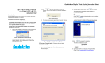
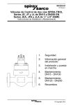
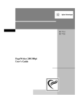
1
Manual BOLDRIN S.r.l. - Via Pitagora, 27 · 35030 Rubano · PD · ITALY 0. List of contents 1. Design and Function 1.1. Description 1.2. Function 1.3. Meter sizes 1.4. Dimensions 1.5. Construction 1.5.1. Main housing 1.5.2. Measuring cartridge 1.5.3. Counter head 1.5.4. Flow conditioner 1.5.5. Oil lubrication 1.6. Materials 1.7. Measurement and pulse outputs 1.7.1. Counter head 1.7.2. NF-Reed-Contacts 1.7.3. NF-NAMUR-Pulse sensors 1.7.4. HF-NAMUR-Pulse sensors 1.7.4.1. HF1 and HF2 1.7.4.2. HF3 up to HF6 1.7.5. Link specification of the electrical pulse sensors 1.7.5.1. Pulse sensors in the counter head 1.7.5.2. Pulse sensors in the meter body 1.7.5.3. Technical data of the Reed-Contacts 1.7.5.4. Technical data of the NAMUR-Pulse sensors 1.7.6. Pressure measurement 1.7.7. Temperature measurement 1.8. Designation and signs 2. Measuring values 3. Measuring accuracy 3.1. Error of the measurement principle 3.2. Error of the installation 4. Pressure loss 5. Transport and storage 6. Installation 7. Putting into operation 8. Maintenance and lubrication 9. Verification Tel. +39.049.89.75.462 (5 linee r.a.) · Fax +39.049.89.75.474 E-mail: [email protected] · Internet http:\\www.boldringroup.it __________________________________________________________________________________________________________________________________________________________________________________________________________________________________ __________________________________________________________________________________________________________________________________________________________________________________________________________________________________ The turbine gas meters CGT serve for the volume measurement of flowing gases. They were developed by the company BOLDRIN in close co-operation with the oil and gas industry. The standard version is appropriate for the gases in table 1 for pressure rates up to 100 bar. The operating pressure amounts to thus 0 to pmax the appropriate pressure rate of the meter. Table 1. List of appropriate gases for the measurement with turbine gas metes in standard version Gas Argon Ethylene Butan Ethan Natural gas Helium Carbon dioxide Carbon monoxide Air Methan Propane Nitrogen Hydrogen Symbol (chemical formula) Ar C2H4 C4H10 C2H6 He CO2 CO CH4 C3H8 N2 H2 Density ρn* [kg/m³] Density relating to air 1,78 1,26 2,71 1,36 ~0,83 0,18 1,97 1,25 1,29 0,72 2,01 1,25 0,09 1,38 0,98 2,09 1,06 ~0,64 0,14 1,53 0,97 1,00 0,55 1,56 0,97 0,07 *(ρn at 1,01325 bar and 273,15 K) The gas meters are specified by the following parameters: Nominal size DN, maximal operating pressure pmax, as well as maximum flow Qmax and minimum flow Qmin under operating pressure and operating temperature. The admissible error between Qmax and Qmin under operating conditions is determined by the margins of error of turbine gas meters as per EEC guideline for volume gas meters. The minimum flow results from the pattern approval, the Verification Ordinance - General Provisions, annex 7 and TRG 7 for testing with high pressure gas. 1.2. Function The measurement principle of the turbine gas meter is based on the proportionality of the linear gas rate for the rotating speed of the turbine wheel in the defined annular space of the measuring cartridge. This area of the gas meter was designed according to the laws of the mechanical measuring technique of liquids and gases. Counter sums up the passed gas volume and brings it to the display. BOLDRIN S.r.l. - Via Pitagora, 27 · 35030 Rubano · PD · ITALY 1.1. Description Tel. +39.049.89.75.462 (5 linee r.a.) · Fax +39.049.89.75.474 E-mail: [email protected] · Internet http:\\www.boldringroup.it 1. Design and Function __________________________________________________________________________________________________________________________________________________________________________________________________________________________________ Table 2. Standard sizes of the turbine gas meters CGT G-Size maximum flow Qmax minimum flow Qmin 40 65 100 160 250 160 250 400 400 650 1000 650 1000 1600 1000 1600 2500 1600 2500 4000 [m³/h] 65 100 160 250 400 250 400 650 650 1000 1600 1000 1600 2500 1600 2500 4000 2500 4000 6500 [m³/h] 6 10 8 13 20 13 20 32 32 50 80 50 80 130 80 130 200 130 200 320 DN mm inch 50 2 80 3 100 4 150 6 200 8 250 10 300 12 Measure NF1 – NF4 ment Counter head range pulse rate Ua m³/Imp. 1:10 0,1 1:20 1 1:20 1 1:20 1 10 1 1:20 10 1:20 10 1:20 10 HF1 – HF2 Counter head m³/Imp. 1,84929E-04 3,69858E-04 9,24645E-04 1,18519E-03 2,12954E-03 7,22932E-04 1,44586E-03 2,58587E-03 2,58587E-03 4,57365E-03 7,75761E-03 8,61957E-03 8,61957E-03 1,44586E-02 1,72391E-02 1,72391E-02 2,97619E-02 3,08315E-02 3,08315E-02 5,35645E-02 HF3 – HF6 Turbine- and Reference wheel m³/Imp. 6,10862E-06 1,01810E-05 2,34947E-05 3,26246E-05 5,86196E-05 3,40498E-05 5,95871E-05 1,06569E-04 1,06569E-04 1,50792E-04 2,55766E-04 2,84185E-04 2,84185E-04 4,76697E-04 4,73641E-04 4,73641E-04 8,17701E-04 8,47089E-04 8,47089E-04 1,47167E-03 1.4. Dimensions The external dimensions of the turbine gas meters can you take from the table 3. An allocation of the parameters takes place according to the figure 1. The dimensions are to be considered when planning from measuring systems. figure 1: External dimensions of the turbine gas meter CGT BOLDRIN S.r.l. - Via Pitagora, 27 · 35030 Rubano · PD · ITALY The standard sizes of the BOLDRIN turbine gas meters are arranged in table 2. On request also the supply of larger nominal sizes is possible. Tel. +39.049.89.75.462 (5 linee r.a.) · Fax +39.049.89.75.474 E-mail: [email protected] · Internet http:\\www.boldringroup.it 1.3. Meter sizes __________________________________________________________________________________________________________________________________________________________________________________________________________________________________ G* L DN Pressure H A C E F Dz D0 d0 n Weight mm rate mm mm mm mm mm mm mm mm mm kg PN10/16 g 286 203 150 165 125 18 4 8 PN10/16 f 286 203 150 165 125 18 4 9 PN25/40 f 286 203 226 165 125 18 4 10 50 PN63 150 92 f 294 203 226 180 135 22 4 12 ANSI150 g 280 203 150 152,4 120,7 19,1 4 8 ANSI150 f 280 203 150 152,4 120,7 19,1 4 9 ANSI300/600 f 286 203 226 165,1 127 19,1 8 17 PN10/16 g 315 215 146 200 160 18 8 18 PN10/16 f 301 206 146 200 160 18 8 19 PN25/40 f 301 206 222 200 160 18 8 23 80 PN63 240 145 f 306 206 222 215 170 22 8 26 ANSI150 g 311 215 146 190,5 152,4 19,1 4 19 ANSI150 f 297 206 146 190,5 152,4 19,1 4 20 ANSI300/600 f 302 206 222 209,6 168,1 22,4 8 29 PN10/16 g 340 229 157 220 180 18 8 23 PN10/16 f 320 220 157 220 180 18 8 24 PN25/40 f 332 220 233 235 190 22 8 30 PN63 f 338 220 233 250 200 26 8 40 100 ANSI150 300 176 g 345 229 157 228,6 190,5 19,1 8 24 ANSI150 f 329 220 157 228,6 190,5 19,1 8 25 ANSI300 f 336 220 233 254 200,2 22,4 8 42 ANSI600 f 347 220 233 273,1 215,9 25,4 8 52 PN10/16 g,s 400 256 185 285 240 22 8 47 PN10/16 f 377 247 185 285 240 22 8 65 PN25/40 s 407 256 264 300 250 26 8 60 PN25/40 f 390 247 261 300 250 26 8 67 PN63 s 430 256 264 345 280 33 8 72 PN63 f 409 247 261 345 280 33 8 80 150 ANSI150 270 g,s 450 397 256 185 279,4 241,3 22,4 8 48 ANSI150 f 380 247 185 279,4 241,3 22,4 8 50 ANSI300 s 416 256 264 317,5 269,7 22,4 12 75 ANSI300 f 398 247 261 317,5 269,7 22,4 12 85 ANSI600 s 435 256 270 355,6 292,1 28,4 12 105 ANSI600 f 412 247 261 355,6 292,1 28,4 12 115 PN10 g,s 441 270 202 340 295 22 8 70 PN10 f 432 261 202 340 295 22 8 75 PN16 g,s 441 270 202 340 295 22 12 70 PN16 f 432 261 202 340 295 22 12 75 PN25 s 451 270 278 360 310 26 12 80 PN25 f 442 261 278 360 310 26 12 90 PN40 s 459 270 282 375 320 29,5 12 95 PN40 f 450 261 278 375 320 29,5 12 105 200 PN63 600 360 s 479 270 282 415 345 36 12 120 PN63 f 470 261 278 415 345 36 12 130 ANSI150 g,s 443 270 202 342,9 298,5 22,4 8 70 ANSI150 f 434 261 202 342,9 298,5 22,4 8 80 ANSI300 s 462 270 282 381 330,2 25,4 12 125 ANSI300 f 453 261 278 381 330,2 25,4 12 135 ANSI600 s 481 270 282 419,1 349,3 31,8 12 160 ANSI600 f 472 261 278 419,1 349,3 31,8 12 175 * (G → housing versions: g - from cast irons; s - from steel with welded connecting pieces; f - from steel turned) Tel. +39.049.89.75.462 (5 linee r.a.) · Fax +39.049.89.75.474 E-mail: [email protected] · Internet http:\\www.boldringroup.it Dimensions and weights of the turbine gas meter CGT (part 1). BOLDRIN S.r.l. - Via Pitagora, 27 · 35030 Rubano · PD · ITALY Table 3. __________________________________________________________________________________________________________________________________________________________________________________________________________________________________ G* L D0 d0 n Weight DN Pressure H A C E F Dz mm rate mm mm mm mm mm mm mm mm mm kg PN10 s 497 298 232 395 350 22 12 125 PN16 s 502 298 232 405 355 26 12 130 PN25 s 512 298 308 425 370 29,5 12 150 250 PN40 750 420 s 524 298 308 450 385 32,5 12 170 PN63 s 534 298 308 470 400 36 12 195 ANSI150 s 503 298 232 406,4 362 25,4 12 140 ANSI300 s 522 298 308 444,5 387,4 28,4 16 200 ANSI600 s 553 298 308 508 431,8 35,1 16 255 PN10 s 547 323 258 445 400 22 12 180 PN16 s 554 323 258 460 410 26 12 190 PN25 s 567 323 334 485 430 29,5 16 210 300 PN40 900 550 s 582 323 334 515 450 32,5 16 230 PN63 s 590 323 334 530 460 36 16 275 ANSI150 s 566 323 258 482,6 431,8 25,4 12 200 ANSI300 s 585 323 334 520,7 450,9 31,8 16 280 ANSI600 s 604 323 334 558,8 489 35,1 20 360 * (G → housing versions: g - from cast irons; s - from steel with welded connecting pieces; f - from steel turned) 1.5. Construction The turbine gas meter consists of 5 main components: Figure 2: Sectional view of the turbine gas meters CGT Tel. +39.049.89.75.462 (5 linee r.a.) · Fax +39.049.89.75.474 E-mail: [email protected] · Internet http:\\www.boldringroup.it Dimensions and weights of the turbine gas meter CGT (part 2) BOLDRIN S.r.l. - Via Pitagora, 27 · 35030 Rubano · PD · ITALY Table 3. __________________________________________________________________________________________________________________________________________________________________________________________________________________________________ 1.5.2. Measuring cartridge The measuring cartridge contains the turbine wheel and starting from nominal size DN 100 optionally the reference wheel, which are hold by means of lubricated or self lubricated ball bearings on the main shaft. The rotating motion of the main shaft will be reduced by gear wheels and transferred to the magnetic coupling. A direct detecting of the rotating motion of the turbine- or reference wheel as high frequency impulse is additionally possible by the optional installation of up to two HF sensors each. 1.5.3. Counter head The transfer of the angular momentum from the main housing loaded by pressure into the counter head is made by a gas tight magnetic coupling. In the counter heading a further reduction of the rotating speed of the waves is made by snail and gear wheels up to the drive of the 8-digit roll counter. A gear set is to be implemented changeable to realise an adjustment of the roll counter. To pick up electrical impulses is given a possibility by up to two HF Namur sensors, up to two NF Namur sensors and up to two NF Reed contacts. As standard, each counter is equipped with one NF Reed contact. The electrical connection, to take the impulses from the counter head can take place over up to two sockets, whereby one socket is installed as standard. The output signals of the HF sensors in the counter operate adjustmentindependently proportionally to the HF sensors on the turbine or reference wheel of the meter. 1.5.4. Flow conditioner The turbine gas meter has an integrated flow conditioner on the upstream site. This ensures according to our PTB certification, that the request of the OIML recommendation IR 32/89 as well as the TRG 13 are fulfilled concerning the incident flow. 1.5.5. Oil lubrication Main shaft bearing of the turbine gas meters CGT can be executed self lubricated or with lubrication over oil pump. For the periodic lubrication the meter is equipped with a hand oil pump, with oil reservoir for an oil amount of filling up to 20 cm³. All other bearings are self lubricated. Depending on the gas flow direction and installation position the oil pump can be attached in such a way that an operation of the front is possible. BOLDRIN S.r.l. - Via Pitagora, 27 · 35030 Rubano · PD · ITALY Housings of the pressure rates to ANSI 150 and nominal sizes to DN 200 can be made of casting. For pressure rates to ANSI 600 the housings in smaller nominal sizes from forging steel are manufactured or welded together with larger nominal sizes from different parts. The dimensions and weights of the meters are indicated in table 3. The installation of the meters is made by DIN or ANSI of flanges. For detecting of the operating pressure at the meter, is at the front and rear side one pr - connecting piece each in form of a tapped hole M 12 x 1,5 available. Starting from nominal size DN 100, the installation of two temperature pockets into the meter body is possible. Tel. +39.049.89.75.462 (5 linee r.a.) · Fax +39.049.89.75.474 E-mail: [email protected] · Internet http:\\www.boldringroup.it 1.5.1. Main housing BOLDRIN S.r.l. - Via Pitagora, 27 · 35030 Rubano · PD · ITALY Tel. +39.049.89.75.462 (5 linee r.a.) · Fax +39.049.89.75.474 E-mail: [email protected] · Internet http:\\www.boldringroup.it __________________________________________________________________________________________________________________________________________________________________________________________________________________________________ 1.6. Materials All by the construction of the turbine gas meters CGT used materials guarantee the necessary stability and corrosion resistance. The meters are material-technically checked before distribution. Appropriate certificates in accordance with DIN EN 10204 can be requested. Meter bodies of the nominal sizes to including DN150 and pressure rates to PN16 can be made from cast irons EN-GJS-400-15 or of steel ST3S. For bodies of the pressure rates up to ANSI 600 steel 18G2 or 19G2 is used. The housings are galvanised and outside coated with varnish paint. Depending on the meter size, the integrated flow conditioner is manufactured from plastic or metal components, aluminium alloys partly combined with stainless steel. The turbine wheel, the measuring cartridge, the meter body, as well as the oil pump are manufactured from aluminium alloys. Moved parts like shafts, snails or bearings consist of stainless steel. Gear and snail wheels are manufactured from plastic. The transparent parts like counter displays or the oil reservoirs of the oil pump consist of polycarbonates. 1.7. Measurement and pulse outputs Figure 3: Measurement outputs of the turbine gas meter CGT __________________________________________________________________________________________________________________________________________________________________________________________________________________________________ 1.7.2. NF-Reed-Contact In the counter head Reed-Contacts (NF1 and NF2) are available depending upon execution up to two, whereby one Reed-Contact NF1 is equipped as standard. They are adjusted like the mechanical roll counter and output pulses, which are in direct relation to the mechanical display. This type of contacts is electric potential free and has a high long-term reliability. Mostly by Reed-Contacts battery powered devices are connected such as volume correctors or tariff devices. You find a representation of the position as well as the connection possibilities in the figures 6 and 7, as well as the specification of the pulse values in table 2. The technical data please take from the paragraph: „Technical data of the Reed-Contacts“. 1.7.3. NF-NAMUR-Pulse sensor NF-NAMUR pulse generators are optionally possible up to two slot initiators (NF3 and NF4) in the counter head They are adjusted like the mechanical roll counter and the Reed-Contacts and output pulses, which are in direct relation to the mechanical display. The use of such active pulse generators is possible due to increased requirement of electric power consumption generally only with line power devices. Thus however pulses can be transferred over larger distances up to approximately 200 m surely. You find a representation of the position as well as the connection types in the figures 6 and 7 as well as the specification of the pulse values in table 2. The technical data please take from the paragraph: „Technical data of the NAMUR-Pulse sensors“. All pulse generators are certified for hazard areas and possess a EEx conformance certificate. 1.7.4. HF-NAMUR-Pulse sensor HF NAMUR pulse generators are optionally possible in the counter heading (HF1 and HF2), at the turbine wheel (HF3 and HF4) and at the reference wheel (HF5 and HF6). The turbine gas meter can be equipped with these sensors according to demand of the customer. The output signals are in fixed relation to the rotation of the turbine wheel and can not be changed by the adjustment gear wheels. They serve generally the control of line powered volume correctors, flow computers or data storage devices. The pulses can be transferred over larger distances up to approximately 200 m surely. The specifications in the table 2 are approximate values, whereby the exact impulse values of an each sensor and meter are determined during the calibration and can deviate from the indicated value in table 2. The technical data please take from the paragraph: „Technical data of the NAMUR-Pulse sensors“. All pulse generators are certified for hazard areas and possess a EEx conformance certificate. BOLDRIN S.r.l. - Via Pitagora, 27 · 35030 Rubano · PD · ITALY The mechanical 8-digit roll counter head is the main counter of the turbine gas meter CGT. It displays the passed gas volume at operating pressure and operating temperature. Depending of the meter size, the display value corresponds to the lowest place 0.01 m³ up to 1 m³. The counter head is rotatable around 345°, so that it is configurable into almost all directions, in order to ensure a good readability in all installations. Tel. +39.049.89.75.462 (5 linee r.a.) · Fax +39.049.89.75.474 E-mail: [email protected] · Internet http:\\www.boldringroup.it 1.7.1. Counter head __________________________________________________________________________________________________________________________________________________________________________________________________________________________________ BOLDRIN S.r.l. - Via Pitagora, 27 · 35030 Rubano · PD · ITALY Tel. +39.049.89.75.462 (5 linee r.a.) · Fax +39.049.89.75.474 E-mail: [email protected] · Internet http:\\www.boldringroup.it 1.7.4.1.HF1 and HF2 This both pulse sensors are positioned in the counter head. There existing reference wheel generates the pulses in up to two approximation initiators (see fig. 4). You find a representation of the position as well as the connection possibilities in the figures 6 and 7. Figure 4: Representation of the HF-pulse sensors HF1 and HF2 in the counter head 1.7.4.2. HF3 up to HF6 The pulse sensors HF3 up to HF6 are positioned in the meter body (see fig. 3). The pulses of the turbine wheel are generated by the sensors HF3 and HF4 and the pulses of the reference wheel by the sensors HF5 and HF6, whereby the last two are only possible starting from the meters with nominal size DN100. Because the reference wheel is positioned on the same shaft like the turbine wheel and the numbers of frames on the reference wheel and the shovels of the turbine wheel are the same, all four pulse generators have the same output frequency. The sensors are approximation initiators and possess in each case a separate plug (see fig. 5). Figure 5: Pattern of the connectors of the HF pulse sensors HF3 up to HF6 in the meter body 1.7.5. Link specification of the electrical pulse sensors Whether a pulse sensor is available and which impulse value of these possesses, you can take from the pulse generator sign of the turbine gas meter (fig. 14). Position of the NF and HF pulse sensors in the counter head of the turbine gas meter CGT NF1 Socket 1 Socket 2 Pin 1 4 2 5 3 6 1 4 2 5 3 6 Polarity − + − + − + − + − + − + x x Figure 7: 1 x 2 x Socket 3 NF3 3 4 x x x x HF1 5 NF2 6 7 8 x Socket 4 NF4 9 10 11 x x x HF2 x 12 x x x x x x x x x x x x x x x x x x x - Standard connection of the complete version - Alternative connections Diagram of connections of the pulse sensors in the counter head of the turbine gas meter CGT BOLDRIN S.r.l. - Via Pitagora, 27 · 35030 Rubano · PD · ITALY Figure 6: Tel. +39.049.89.75.462 (5 linee r.a.) · Fax +39.049.89.75.474 E-mail: [email protected] · Internet http:\\www.boldringroup.it __________________________________________________________________________________________________________________________________________________________________________________________________________________________________ __________________________________________________________________________________________________________________________________________________________________________________________________________________________________ BOLDRIN S.r.l. - Via Pitagora, 27 · 35030 Rubano · PD · ITALY Tel. +39.049.89.75.462 (5 linee r.a.) · Fax +39.049.89.75.474 E-mail: [email protected] · Internet http:\\www.boldringroup.it 1.7.5.1. Pulse sensors in the counter head The position and the connectors of the possible pulse generators in the counter head are represented in the figures 6 and 7. The standard version contains only the NF Reed contact NF1. All other sensors can be installed on customer's request. The connection of the electrical pulses to the installation for clients is made by the sockets So1 and So2, whereby So2 is installed optionally with more than 3 sensors or on customer's request in the counter head. The electrical connection to the socket is to be implemented over a plug of the company Tuchel with the designation C091 31 H006 100 6. An information plate (see fig. 15) of the electrical specification of the socket is positioned on the rear side of the counter head. 1.7.5.2. Pulse sensors in the meter body The position and the connectors of the possible pulse generators in the meter body are represented in the figure 3. The detection of the electrical impulses to the customer installation is made by the respective plugs at the sensor. The electrical connection could be realised to the 4-pin plug by a coupling socket of the company Tuchel with the designation C091 31 D004 100 2. An equipment of the meter with these sensors has to be required in the meter order. A retrofit is possible only, if the appropriate drilling with a thread hole M16x1,5 is available in the meter body, according to figure 8. This retrofitting can be done by the manufacturer only, or executed by assigned technical personnel. Figure 8: Assembly hole for the HF-Pulse sensors HF3 up to HF6 in the meter body 1.7.5.3. Technical data of the Reed-Contacts The Reed-Contacts are passive sensors and used for low-frequency output signals only. They have the following technical data: max switching voltage 24 V max switching current 100 mA contact resistance 0,15 Ω max switching frequency 500 Hz __________________________________________________________________________________________________________________________________________________________________________________________________________________________________ Figure 9: Diagram of connections of the inductive NAMUR initiators inactive state: UL < 1,2 V, active state: UH > 2,1 V Figure 10: Output signals of the inductive NAMUR initiators 1.7.6. Pressure measurement The measurement of the operating pressure of the turbine gas meter can be done by the reference measuring tap pr. These is available at the front and as doubles at the rear side of the meter (see fig. 3). In that way it will take place at the front without attention of the installation position. The thread dimensions for the connection of a screw connector is represented in the figure 11. BOLDRIN S.r.l. - Via Pitagora, 27 · 35030 Rubano · PD · ITALY The NAMUR-Pulse generators are active sensors and used for low or high frequency output signals. They have the following technical data: supply voltage 8,2 V supply current inactive (low) < 1,2 mA supply current active (high) > 2,1 mA load resistance 1 kΩ max switching frequency 5 kHz The circuitry of the electrical connection is represented in figure 9 and the output signals which can be expected in figure 10. Tel. +39.049.89.75.462 (5 linee r.a.) · Fax +39.049.89.75.474 E-mail: [email protected] · Internet http:\\www.boldringroup.it 1.7.5.4.Technical data of the NAMUR-Pulse sensors BOLDRIN S.r.l. - Via Pitagora, 27 · 35030 Rubano · PD · ITALY Tel. +39.049.89.75.462 (5 linee r.a.) · Fax +39.049.89.75.474 E-mail: [email protected] · Internet http:\\www.boldringroup.it __________________________________________________________________________________________________________________________________________________________________________________________________________________________________ Figure 11: Dimensions of the reference measuring tap 1.7.7. Temperature measurement The measurement of the operating temperature can take place in the turbine gas meter of the nominal size DN100 or larger by means of a temperature pocket, installed in the down stream part of the meter body(see fig. 3). The assembly of a second temperature pocket for the reference measurement is oppositely in the area with the same flow condition in the meter possible. In standard version no temperature pockets are installed, but can be ordered however as accessories. Temperature pocket possess an internal thread G ¼“ for the installation of a temperature sensor with a diameter of 6mm. The installation length please take from the figure 12. According to the request of the local verification offices the temperature pocket is to be filled with heat conducting oil or heat conducting paste. DN L [mm] Figure 12: 100 66 150 66 200 72 250 78 300 78 Temperature pocket for the installation into the turbine gas meter CGT 1.8. Designation and signs The technical basic parameters of the turbine gas meter are noted on the type plate (fig. 13). It is equipped on the front of the counter head. The specification concerning pulse outputs and their value can be taken from the pulse generator sign on the top side of the counter head (fig. 14). The flow direction is indicated by arrows (fig. 16) on the front and rear side of the meter body. The marking of the pressure and temperature measuring points takes place at the meter body according to the representation in figure 17. In similar manner also the pulse generators HF3 up to HF6 are marked. type plate Figure 14: Pulse sensor sign Figure 15: Sign for the connector identification of the pulse generators in the counter head Figure 16: Arrow on the meter body for the specification of the flow direction Figure 17: Information designation for the pressure and temperature measurement BOLDRIN S.r.l. - Via Pitagora, 27 · 35030 Rubano · PD · ITALY Figure 13: Tel. +39.049.89.75.462 (5 linee r.a.) · Fax +39.049.89.75.474 E-mail: [email protected] · Internet http:\\www.boldringroup.it __________________________________________________________________________________________________________________________________________________________________________________________________________________________________ __________________________________________________________________________________________________________________________________________________________________________________________________________________________________ BOLDRIN S.r.l. - Via Pitagora, 27 · 35030 Rubano · PD · ITALY Tel. +39.049.89.75.462 (5 linee r.a.) · Fax +39.049.89.75.474 E-mail: [email protected] · Internet http:\\www.boldringroup.it 2. Measuring values The gas volume, which flows through a turbine gas meter, is displayed by the counter concerning the operating or line conditions pressure, temperature and compressibility only. In order to determine a comparable value independently to the respective operating conditions for accounting purposes, a conversion of the volume to standard conditions Vn is used. The standard volume determines itself from the following calculation: Vb pb Tn Vb 273 * (pü + 1) Vn = — * — * — ≈ — * ————— k pn Tb Z (t + 273) Definition: Vb – operating volume [m³/h] Tb Vn – standard volume [m³/h] Tn pb – operating pressure at the meter [bar] k pü – operating over pressure at the meter [bar] pn – standard pressure [bar] (1,01325 bar) Z t – operating gas temperature [°C] Zn (1) where k = Z/Zn – standard gas temperature abs. [K] (273,15 K) – operating gas temperature abs. [K] – compressibility factor k (constant or calculation by GERG 88) – real gas factor – real gas factor (standard condition: Zn ≅ 1) The operation volume Vb of an accounting period determines itself from the difference of the counter statuses of the turbine gas meter the at the beginning and to the end of the period. The operation over pressure pü is determined on the reference pressure point pr of the meter as average value. The operation gas temperature t is determined as average value measured by a temperature sensor in the meter body or in the down stream pipe of the meter in accordance with PTB test rules Volume 20. The compressibility factor is determined by using the gas quality, at systems up to 10 bar as constant or at higher pressures than variable over calculation methods in accordance with G 486. 3. Measuring accuracy Each real measurement is falsified by measurement inaccuracies. These errors can be divided at the turbine gas meter in two substantial categories: 1. Error by the physical characteristics of the measurement principle. 2. Error by the installation-conditioned influence of the gas flow. 3.1. Error of the measurement principle The measuring characteristic of turbine gas meters is represented in figure 18. According to the EWG guideline of volume gas meters the margins of error are determined on the following values: Qt – Qmax Qmin – Qt ≤ ± 1% ≤ ± 2% where at turbine gas meter Qt = 0,2 Qmax Error characteristic of a turbine gas meter Low pressure error curve; - - - - - - High pressure error curve The measurement range of the BOLDRIN turbine gas meters is indicated in table 2. As more highly the operating pressure rises, becomes the error curve more flatter (see fig. 18) and the minimum flow Qmin becomes more smaller within the admissible limits of error. Thus a larger measuring range can be obtained with higher operating pressures, which can be certified also according to TR G 7 up to a relation of 1:50. The on density depending minimum flow value Qmin,ρ can be calculated according to the following relation: Qmin,ρ = Qmin * iρ = Qmin * ρw — = Qmin * ρ ρw * 1,013 Qmin ————— ≈ 1,1 * —————— ρg * (p + pa) ρg * (p + pa) (2) Definition: Qmin,ρ – minimum flow value under operating pressure [m³/h] Qmin – minimum flow value according to table 2 [m³/h] iρ – coefficient ρw – density of the gas of the verification [kg/m³] ρ – density of the operation gas with operating pressure [kg/m³] – density of the operation gas with atmospheric pressure according to table 1 [kg/m³] ρg p – gas overpressure in front of the turbine gas meter [bar] pa – atmospheric pressure [bar] The figure 19 shows a diagram to the determination of Qmin,ρ with determined operating pressure. Based on the operating pressure and the temperature it has to be determined the density. In dependency of this density values, the coefficient iρ can be determined from the right page of the diagram. Under help of the formula in the diagram (fig. 19) it is possible to calculate the appropriate Qmin,ρ under operating pressure by using the Qmin value from table 2. BOLDRIN S.r.l. - Via Pitagora, 27 · 35030 Rubano · PD · ITALY Figure 18: Tel. +39.049.89.75.462 (5 linee r.a.) · Fax +39.049.89.75.474 E-mail: [email protected] · Internet http:\\www.boldringroup.it __________________________________________________________________________________________________________________________________________________________________________________________________________________________________ BOLDRIN S.r.l. - Via Pitagora, 27 · 35030 Rubano · PD · ITALY Tel. +39.049.89.75.462 (5 linee r.a.) · Fax +39.049.89.75.474 E-mail: [email protected] · Internet http:\\www.boldringroup.it __________________________________________________________________________________________________________________________________________________________________________________________________________________________________ Figure 19: Diagram for the determination of the Qmin - value at defined operating pressure and operating temperature __________________________________________________________________________________________________________________________________________________________________________________________________________________________________ 4. Pressure loss The gas meter causes an inevitable pressure loss. This is limited by the maximum value according to DIN 33800. The pressure loss values of the individual nominal sizes at a gas density ρ0 = 1kg/m³, that can be taken from the diagram of the figure 20. The real pressure loss ∆pre is calculated according to the following formula: ρ ∆pre = — ρ0 * pa + p ——— ∆p pa (3) Definition: ρ – gas density according to table 1 ∆pre – operating pressure loss ρ0 – reference gas density (ρ0 = 1kg/m³) p – gas over pressure in front of the meter ∆p – pressure loss for gas density ρ0 (Abb.20) pa – atmospheric pressure (pa = 1bar) Figure 20: Pressure loss diagram of the turbine gas meter CGT of a density ρ0 = 1 kg/m³ BOLDRIN S.r.l. - Via Pitagora, 27 · 35030 Rubano · PD · ITALY Turbine gas meters are inferential gas meters and therefore dependent on the direction, distribution and the homogeneity of the gas flow. The integrated flow conditioner guarantees under considering of the minimum requirements as per OIML recommendation IR 32/89 also without additional flow conditioner in the upstream pipe the adherence of the error limits. There it means, that with an upstream pipe length of 2xD regardless of any perturbations the error deviation is not larger than 0.3%. In the case of pulsating or intermittent gas flows, which cause a run after of the turbine wheel of over 1% in relation to the operation flow, a turbine gas meter without special add-on modules is not suitable. In these cases volume measuring instruments should be used, as for example the BOLDRIN rotary gas meters CGR. Tel. +39.049.89.75.462 (5 linee r.a.) · Fax +39.049.89.75.474 E-mail: [email protected] · Internet http:\\www.boldringroup.it 3.2. Error of the installation BOLDRIN S.r.l. - Via Pitagora, 27 · 35030 Rubano · PD · ITALY Tel. +39.049.89.75.462 (5 linee r.a.) · Fax +39.049.89.75.474 E-mail: [email protected] · Internet http:\\www.boldringroup.it __________________________________________________________________________________________________________________________________________________________________________________________________________________________________ In the case if a complete meter run with upstream and downstream pipe, temperature pockets and a Sprenkle flow conditioner will be used, a calculation of the pressure loss by the same formula is possible. The pressure loss value ∆p of the complete meter run is to be inferred thereby from the pressure loss diagram in figure 21. Figure 21: Pressure loss diagram meter run of a density ρ0 = 1 kg/m³ 5. Transport and storage The turbine gas meter CGT is a precise measuring instrument and is to handle with the utmost caution. The following points are to be considered: During transportation the meter is not to be thrown or to expose strong vibrations. Special caution is required for loading and unloaded of high pressure meters, in the case of a large mass. The transportation of the meter has to be done with emptied storage vessel of the oil pump. The meter is to be transported and to be stocked in the appropriate installation position. At meters with oil pump it is to be paid attention, that they may be brought only briefly into another position than the installation position. The gas meter should be transported in the original packaging up to the place of work. Removing from fabrication catches and transportation covers is only recommendable at the installation place. A raising of the turbine gas meter at the counter head is not admissible. For the movement of heavy devices the transport eyes are to be used. It is to be paid attention to as dry a storage as possible. The meter is to be protected against precipitation and other humidity. It is to be made certain that by the transportation and by remove of the packing no verification seal is damaged or is removed, since otherwise the official verification is lost. Storing gas meters do not need to be lubricated. For mentioned above transport damages the manufacturer does not take over a warranty. __________________________________________________________________________________________________________________________________________________________________________________________________________________________________ BOLDRIN S.r.l. - Via Pitagora, 27 · 35030 Rubano · PD · ITALY Before the gas meter is installed, it should be checked again, if the meter meets the requirements of to the gas measuring system. Very important is the check of the pressure rate PN of the installation, the maximum installation pressure pmax and maximum the flow rate Qmax under operating conditions, as well as the right flow direction. The preferred position for the installation of the turbine gas meter is an horizontal installation. The counter head has to be above in each case. A vertical installation has to be adapt by the production. Specially the flow direction from down upward is to be avoided and possible only by special manufacturing. The gas meter has not to be installed at the deepest point of the installation, because otherwise condensate or contamination can settle in the meter and thus the function and measuring accuracy can be affected. The installation of turbine gas meters should take place in closed rooms or cabinets if possible. In open air installations the meter has to be protected by suitable measures from precipitation, contamination or direct sun exposure. The area of application is with a gas temperature between -10°C and +60°C. The lowest ambient temperature has to be not lower than -25°C. The installation, into which the turbine gas meter is to be installed, is to be conceived according to the technical guideline TR G 13, because otherwise by the manufacturer no warranty for the adherence of the error limits can be given. The BOLDRIN turbine gas meter passed the perturbation approval according to the OIML recommendation IR-32/89, annex A with easier and heavy perturbation. For installation of BOLDRIN turbine gas meters the conditions of the paragraph 1 of the technical guideline TR G 13 have been valid, that means to adherence the measuring accuracy an upstream pipe distance of 2 x DN is sufficient. It is to be made certain too, that the gas flow does not indicate an intermittent or pulsating character, which can cause a tracking error of ≥1%. In order to achieve a very high measuring accuracy of the gas meter, the company offers also complete meter runs with upstream and downstream pipe, temperature pockets in the downstream pipe and a BOLDRIN flow straighter. This flow straighter is a Sprenkle Flow conditioner according to DIN EN ISO 5167-1. The pressure loss thus increased is to be inferred from the paragraph of the same name. The installation of the gas meter has to take place without tension into the piping. With larger meters the pipe installation, or if necessary the meter, is to be supported. It is to be made certain that the meter is to be built concentrically into the piping and no seals loom into the piping. It has to be paid attention of possible contamination of the gas, which can damage the meter and cause an influence of the measuring accuracy strongly. If possible, a filter has to be installed in front of gas meter, which has a fineness of minimal 10µm. In the starting phase a start sieve is recommendable, which avoids a damage of the meters by welding or installation pollution. This is to be removed however after some time again from the pipe installation, in the case of contamination which were held back by the start sieve, will generate a flow disturbance, which can have an influence on the measuring accuracy. The manufacturer of the turbine gas meters does not take responsibility for damage to the gas meter, which from insufficient filtering or contamination in the piping results. Tel. +39.049.89.75.462 (5 linee r.a.) · Fax +39.049.89.75.474 E-mail: [email protected] · Internet http:\\www.boldringroup.it 6. Installation __________________________________________________________________________________________________________________________________________________________________________________________________________________________________ BOLDRIN S.r.l. - Via Pitagora, 27 · 35030 Rubano · PD · ITALY Tel. +39.049.89.75.462 (5 linee r.a.) · Fax +39.049.89.75.474 E-mail: [email protected] · Internet http:\\www.boldringroup.it The connection of volume correctors and add-on modules has to take place using the prescribed plug connectors (paragraph "link specification of the electrical pulse generators"). 7. Putting into operation If the gas meter is equipped with an oil pump, the bearings have to be lubricated in accordance with servicing instruction before start-up. During the admission of the turbine gas meter with operating pressure largest caution is required, because by the difference of pressure for pressure-free subsequent installation briefly large gas flows can occur, which can load then the gas meter over the permitted flow and destroy the measuring cartridge. Filling the pipe installation by the installed turbine gas meter should be avoided. You find an example of the structure of a measuring system in figure 22. – case a bypass in the installation is available, is before opening the valves 1 and 2 pre and behind the gas meter the following piping through to open the valve 4, to be filled. Afterwards over a needle valve 5, if it is available, or by very slow opening of input valve 1 the meter can be set under operating pressure. After it the output valve 2 is only opened slowly. As last step may not be forgotten to close the valves 4 and 5 again. – with absence of the bypass at first the meter is by slow opening of the output valve 2 to connect with that follows installation. Afterwards very slowly and carefully the input valve 1 is to be opened, whereby the danger of the brief overload is very large here. – for the purpose of the disassembly the meter installation has to be emptied. If a bypass is available, the valve 4 is opened as the first one. The meter has to be separated from the gas flow by slowly close from the input valve 1 and the output valve 2. Afterwards the gas meter is to be emptied over the bleed valve 3 slowly. Figure 22: Pattern of a measuring system with bypass __________________________________________________________________________________________________________________________________________________________________________________________________________________________________ Turbine gas meters has to be serviced from instructed technical personnel only. Strong operation noises or jerky run point on a damage of the gas meter. Additional there is a controllability, if pulses of the reference wheel and the turbine wheel of the turbine gas meter are compared by a volume corrector or a flow computer. The deviations of the relation of the calibrated impulse values must be below 1%. In these cases the meter is to be repaired by the manufacturer or a certified workshop. To put the meter into custody transfer again, the meter has to be official verified one’s more. Turbine gas meters with oil pump are to be lubricated periodically. Depending of the composition of the gas escort substances and the stressing of the turbine gas meter, by the measurement application of gases of the 2. gas family according to G 260/I, a lubrication all 1 to 2 months is recommend. With the application for the measurement of rotten gas, strongly dirty or other aggressive gases, the reduction of the lubrication interval by 1 time weekly is necessary. For measurement other gases please co-ordinate the lubricant with our factory, which can be used. Depending upon pressure range the turbine gas meter can be equipped with a pushbutton oil pump or a lever oil pump. A complete stroke of the oil pump supplies approx. 1/3 cm³ oil to the main bearings. The recommended stroke rate for a lubrication cycle is indicated in table 4. Recommended stroke rate of the oil pump for each lubrication cycle Nominal size DN50, DN80, DN100 DN150, DN200 DN 250, DN300 Stroke rate 5 10 15 At each lubricating the oil level in the storage vessel of the oil pump is to be controlled. To the refill Lubrina oil of the company BOLDRIN is recommended. The following Lubrina types of oil are offered by BOLDRIN for it: DN50 and DN80 Lubrina-Öl L12 Viscosity approx.12 mm²/s at 20°C ≥DN100 Lubrina-Öl L23 Viscosity approx. 23 mm²/s at 20°C For in table 1 specified gases the following of oils can be used too: DN50 and DN80 Isoflex PDP10 ≥DN100 Isoflex PDP38 or Aeroshell Fluid 12 9. Verification The turbine gas meter CGT of the company BOLDRIN possesses an EEC pattern approval for custody transfer. After the EEC initial verification the meter will be sealed and is thus usable for the period of the calibration validity period according to Verification Ordinance General Provisions, appendix B for custody transfer. Reverification or an in-service testing can be executed by each accredited testing laboratories. BOLDRIN S.r.l. - Via Pitagora, 27 · 35030 Rubano · PD · ITALY Table 4 Tel. +39.049.89.75.462 (5 linee r.a.) · Fax +39.049.89.75.474 E-mail: [email protected] · Internet http:\\www.boldringroup.it 8. Maintenance and lubrication __________________________________________________________________________________________________________________________________________________________________________________________________________________________________ BOLDRIN S.r.l. - Via Pitagora, 27 · 35030 Rubano · PD · ITALY Tel. +39.049.89.75.462 (5 linee r.a.) · Fax +39.049.89.75.474 E-mail: [email protected] · Internet http:\\www.boldringroup.it The gas meter loses its permission for the application of custody transfer, if a seal were damaged or removed. The seal positions can be taken from the figure 23. Figure 23: Seal positions of the turbine gas meter CGT Seals for add-on modules are not marked. At special information it is pointed out, that blind screw connections which are not be used by sensors, can be sealed too. Also with a break of these apparently unnecessary security seals the calibration validity of the measuring instrument goes out.