1
GasAlertMicroClip Soft Tools [English] Instruction Sheet
BG TECHNOLOGIES
. Soft Tools will automatically install Java
2. Click
Runtime. When Java has installed, the Soft Tools Setup pop-up
displays.
GasAlertMicroClip Soft Tools
Instruction Sheet
4.
From the Software Install window, click
to proceed.
The install program automatically creates a folder on the
C: drive for the software.
Or
Introduction
Click
and then click
The GasAlertMicroClip Soft Tools application is required to configure the
GasAlertMicroClip detector (“the detector”).
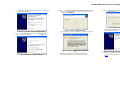
Figure 2. Setup Pop-up
Software/Hardware Installation
3.
a Important
to select a different location to save the software
.
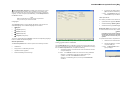
The installation requires approximately 20 seconds. When the
software installation is complete, the following window displays.
The setup process requires approximately 30 seconds. When the
setup is loaded, the following window displays.
Complete the entire installation process for both the software (Soft
Tools) and the hardware (IR Link) before removing the Soft Tools
CD or operating the Soft Tools program.
Do not insert the USB cable into the computer until instructed in
the following procedures.
1.
Insert the Soft Tools CD into the computer. If Java Runtime is not
installed on your computer the following pop-up displays.
Figure 1. Java Runtime Not Found Pop-up
Figure 4. Installation Complete Window
If Java is currently installed, the Soft Tools Setup pop-up
(Figure 2) displays. Allow 20-30 seconds for the pop-up to
display. Proceed to step #3.
Figure 3. Software Installation Wizard Window
5. Click
The software installation is complete.
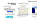
If Setup Pop-up Does Not Display: If the pop-up does not display,
complete the following:
D5914/1 (English)
iERP: 122012
© 2006 BW Technologies LP. All rights reserved. Printed in Canada.
All product names are trademarks of their respective companies.
•
From the desktop, double-click My Computer.
•
Double-click the CD Drive. The setup will automatically begin.
Proceed to step #3.
to complete the installation.
a Important
Do not remove the Soft Tools CD from the
computer.
6.
Connect the IR Link to the USB cable. If required, refer to
Figure 10 and Connecting the IR Link to the Detector.
GasAlertMicroClip Soft Tools [English] Instruction Sheet
7.
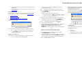
Connect the USB cable to the USB port on the computer. The
following window displays.
9. Click C Install the software automatically (Recommended)
at the bottom of the window. The
and then click
following window displays.
10. Click
. The following window displays.
Figure 9. USB Install Wizard Window
Figure 7. USB Device Search Window
Figure 5. Found New Hardware Wizard Window
8. Click C Yes, this time only and then click
following window displays.
. The
The wizard searches for the USB device. When the computer
locates the USB device, the following window displays.
Figure 8. Hardware Installation Message Window
Note
Figure 6. USB Device Installation Window
The Soft Tools software is thoroughly tested by BW
Technologies and will not harm your computer system.
The installation requires approximately 5-10 seconds. The
following window displays.
Figure 10. Completing the Found New Hardware Window
. The installation
11. When the installation is complete, click
of the software and hardware is complete. Proceed to Getting
Started.
GasAlertMicroClip Soft Tools [English] Instruction Sheet
Connecting the IR Link to the Detector
1.
Activate the detector and wait for start-up to complete.
Sensors
To transfer data between Soft Tools and the detector, refer to Table 1,
Figure 11, and complete the following procedures.
2.
Connect the USB cable to the USB port on the computer.
3.
Connect the USB cable to the IR Link (if required).
The Sensors tab is used to define settings for the sensors and the detector.
The Sensors tab consists of the
4.
Insert the IR Link into the IR interface on the back of the detector.
Table 1. Connecting the Detector to the IR Link
Item
Description
1
Detector
2
IR interface
3
IR Link
4
USB cable
To operate the GasAlertMicroClip Soft Tools program, refer to the following
section, Getting Started.
Getting Started
•
Detector Identification section,
•
sensor fields (used to define settings for the sensors),
•
User Options section (used to define settings for the detector), and
•
Language section (used to set the desired language the detector
displays).
The IR Link is compatible only with Windows XP and higher. Soft Tools is
used to
•
define all of the settings for the sensors,
•
set the user options,
•
save detector settings to a file that can be transferred to additional
detectors,
•
download datalogs and event logs,
•
retrieve settings from a detector that can be used to configure
additional detectors,
•
initiate calibrations, and
•
upgrade firmware.
Using Soft Tools
Soft Tools consists of two tabs that are used to perform functions and define
settings for the sensors and the detector.
Sensors (Figure 12)
Figure 11. Connecting the Detector and IR Link
Device Operations (Figure 13)
Figure 12. GasAlertMicroClip Soft Tools (Sensors Tab)
GasAlertMicroClip Soft Tools [English] Instruction Sheet
Detector Identification
This section provides information about the
•
Serial Number (KA106-123456), and
•
Hardware Revision (1) current firmware the detector is using.
This section also provides two fields that are used to enter text
(e.g., distributor name with 1-800 number or employee name) that will
display on the GasAlertMicroClip detector LCD during start-up.
•
Startup Message Top Line (maximum 25 characters)
•
Startup Message Bottom Line (maximum 25 characters)
Sensor Fields
All settings for the sensors are set from the sensor fields. Individual fields
are provided for each sensor.
•
Carbon Monoxide (CO)
•
Oxygen (O2)
•
Hydrogen Sulfide (H2S)
•
Combustible/LEL
Disabled
5
Cal Interval: Press c or d to define how often calibration must be
performed (0 to 365 days). Select zero (0) to disable the Cal Interval option.
Note
BW recommends that the detector be calibrated once
every 180 days (6 months).
Bump Interval: Press c or d to define how often a bump check must be
performed (0 to 365 days). Select zero (0) to disable the Bump Interval
option.
Note
BW recommends that the detector be bump checked
once every 24 hours prior to the work shift.
Low Alarm: Press c or d to define the low alarm setpoint (0 = disabled).
High Alarm: Press c or d to define the high alarm setpoint (0 = disabled).
TWA Alarm: Press c or d to define the time-weighted average (TWA)
alarm setpoint - for toxic sensors only (0 = disabled).
Disabled: Click inside the checkbox to enable/disable the sensor.
Enabled
Cal Gas: The calibration gas option is used to increase/decrease the gas
concentration level for calibration (it must match the value of the span gas
that is used to calibrate the sensor). Press c or d to increase or decrease
the concentration level for the selected sensor.
STEL Alarm: Press c or d to define the ppm level for the short-term
exposure limit (STEL) alarm setpoint - for toxic sensors only (0 = disabled).
STEL Interval: The short-term exposure limit can be set from 5 to 15
minutes. Press c or d to select the STEL interval (for toxic sensors only).
a Warning
Disabling an installed sensor configures the detector to a
1, 2, or 3-gas unit. Protection is no longer provided from the
gas targeted by the disabled sensor(s). Disabling a sensor
should be performed with extreme caution.
If a sensor fails, disabling the sensor also deactivates the detector alarm.
The sensor should be replaced and enabled as soon as possible. The
detector will function normally with the remaining enabled sensors.
CO/H2S/LEL Auto-Zero on Startup: Enabling this option ensures that
the auto zero sequence automatically initiates during start-up when the
detector is activated.
O2 Auto-Calibration on Startup: Enabling this option ensures that the
O2 sensor is calibrated during start-up when the detector is activated.
LEL By Vol CH4: If this function is enabled, LEL is measured as
% by volume methane.
User Options
The User Options section is used to enable or disable options for the
detector. Unless specified when ordered, the detector is shipped with all
user options disabled.
Click inside the checkbox to toggle between enable/disable.
Enabled
Disabled
5
Confidence Beep: When enabled, this option provides continuous
confirmation that the detector is operating correctly. When the confidence
beep is enabled, the audible alarm beeps once every 10 seconds.
Latching Alarms: Enabling this option causes the low and high gas
alarms (audible, visual, and vibrator) to persist until it is acknowledged by
the user.
Safe Mode: When enabled, the safe mode option confirms that normal
ambient conditions prevail and there are no gas hazards. When all gas
levels are below the alarm setpoints, Safe displays continually on the
detector LCD.
Stealth Mode: If enabled, stealth mode disables the backlight, the visual
alarms, and the audible alarms. Only the vibrator activates during an alarm
displays continually on the detector LCD.
condition. When enabled,
IR Stealth Mode: If enabled, only the infra-red (IR) LEDs and the vibrator
displays continually
activate during an alarm condition. When enabled,
on the detector LCD.
Force Calibration When Overdue: If enabled, this option forces
calibration and prevents the detector from operating if a sensor is overdue
upon start-up. To set a time period (0 to 365 days), locate Cal Interval in
the Sensors section.
Cal Lock: If this option is enabled, calibration can only be completed
(auto zero is still permitted) by
•
pressing C Calibration on the MicroDock II Base Station, or
•
pressing Calibrate on the Device Operations tab in Soft Tools.
BW recommends that the sensors be calibrated every 180 days
(6 months).
GasAlertMicroClip Soft Tools [English] Instruction Sheet
Force Bump When Overdue: If enabled, this option forces a bump
check and prevents the detector from operating if it is overdue upon
start-up. Enabling this option ensures that a bump check is performed
regularly. To set a time period (0 to 365 days), locate Bump Interval in
the Sensors section.
3.
If required, use the O buttons to increase/decrease the Cal Gas
ppm or % level to match the gas cylinder level.
4. Click the Calibrate button to begin calibration. Refer to the
GasAlertMicroClip User Manual for calibration procedures.
Note
Other Operations
BW recommends that a bump check be performed
every 24 hours prior to the work shift.
This section provides function buttons that are used to
Languages
•
upload firmware upgrades (Bootloader),
The Language option is used to display all detector LCD screens in a
selected language. The available languages are as follows:
•
download datalogs (Datalog Downloader), and
•
download event logs ( Event Log Downloader).
•
z English
•
{ Français (French)
•
{ Deutsch (German)
•
{ Español (Spanish)
•
{ Prtuguês (Portuguese)
Bootloader Button: This button is used to upload new firmware revisions.
To obtain firmware revision files, contact BG Technologies.
a Warning
Uploading new firmware automatically clears all datalogs on
the detector. Ensure that all datalogs are transferred to Soft
Tools and then saved to file prior to performing the firmware
update.
The factory default language is English. Click the corresponding language
button to enable the desired language.
To upload new firmware, complete the following:
Figure 13. GasAlertMicroClip Soft Tools (Device Operations Tab)
1.
Obtain the new firmware file and save it to the desired directory.
CO/O2/H2S/LEL Sensor Calibration
2.
The CO/O2/H2S/LEL sensor calibration sections are used to select the gas
ppm and % levels of the sensors being calibrated. To calibrate the sensor(s)
from the Device Operations tab, complete the following:
Activate the detector. Connect the IR Link to the detector and the
computer USB port.
3. Click the Bootloader button. The GasAlertMicroClip Bootloader
pop-up displays.
Device Operations
The Device Operations tab is used to perform the following functions:
•
Calibrations
•
Set ppm and % calibration gas levels
•
Upload firmware upgrades
•
Download datalogs and event logs
1.
Activate the detector. Connect the IR Link to the detector and the
computer USB port.
2. Check
the Calibrate checkbox for each sensor being calibrated.
Example 1: If calibrating using all four gases with a 4-gas
cylinder, check all of the Calibrate checkboxes.
Example 2: If calibrating just CO, click only the CO Calibrate
checkbox.
Figure 14. Upload Firmware Update
GasAlertMicroClip Soft Tools [English] Instruction Sheet
4. Click Upload Firmware Update. The Choose Firmware File to
Upload window opens.
5.
1.
Select the required firmware file and click Open. The firmware
begins uploading. The upload process requires approximately 30
seconds. When the upload is completed, Firmware Update
Successful displays.
Datalog Downloader Button: This button is used to transfer datalogs from
the detector to a file/folder that can be opened/displayed in a software
application such as,
Activate the detector. Connect the IR Link to the detector and the
computer USB port.
3.
Excel: Locate the file and double-click. The file automatically
opens in the default application Excel.
Other Applications: Open the file from the desired application.
Transferring Settings
There are several options available to communicate data between Soft
Tools and the detector. Each option is accessed via the buttons located at
the bottom of the window.
•
Save To Device
Excel (default), and
•
Retrieve From Device
Access, Word, and Notepad (future options).
•
Save To File
•
Load From File
•
Fleet Manager (future option),
•
•
To download a datalog, complete the following:
1.
Activate the detector. Connect the IR Link to the detector and the
computer USB port.
2. Click the Datalog Downloader button. The datalog(s)
automatically begin downloading. A browser opens.
3.
Excel: Locate the file and double-click. The file automatically
opens in the default application Excel.
Other Applications: Open the file from the desired application.
Event Log Downloader Button: This button is used to transfer event logs
from the detector to a software application such as,
•
Fleet Manager (future option),
•
Excel (default), and
•
Access, Word, and Notepad (future options).
3.
2. Click the Event Log Downloader button. The event log(s)
automatically begin downloading. A browser opens.
The detector then verifies the firmware and reprograms itself for
approximately 10 seconds. The detector automatically resets to
run the new firmware.
If an error message displays that the firmware upload was not
successful, refer to Troubleshooting.
2. From the Sensors tab, select settings, make modifications, or
open a saved file of previously configured settings (click Load
from File button to load saved settings).
To download an event log, complete the following:
Successful: The status bar at the bottom of the window changes to green
and displays the function performed and that it was successful.
Example: Save to Device Successful
When all of the settings are confirmed, click Save to Device to
transfer the settings to the detector.
Retrieve from Device
The Retrieve From Device button is used to retrieve the current settings of
a detector. From the Sensors tab, the displayed settings can then be
•
viewed,
•
modified,
•
used to setup other detectors, and/or
•
saved to file.
1.
Activate the detector. Connect the IR Link to the computer and
the detector.
2.
Open Soft Tools.
3. Click Retrieve from Device. The current settings of the detector
display on the Sensors tab.
Save to File
Settings can be saved to files that can be used to set up additional
detectors and/or to maintain a record of detector settings.
Unsuccessful: If the retrieval fails, the status bar at the bottom of the
window changes to red and displays the function performed and that it was
unsuccessful. Repeat steps #1-4 again. If still unsuccessful, contact
BW Technologies.
1. From the Sensors tab, select the sensor settings and
enable/disable the required user and language options.
Example: Save to Device Unsuccessful
3.
2. Click
Save To File. The browser opens.
Select the required file/folder and click Save.
Save to Device
Load from File
The Save To Device button is used to transfer the currently displayed
settings on the Sensors tab to the detector.
The Load From File button is used to access and display files of saved
settings.
1.
Activate the detector. Connect the IR Link to the detector and the
computer USB port.
1.
From Soft Tools, press Load From File to access the browser.
GasAlertMicroClip Soft Tools [English] Instruction Sheet
From the drop-down menu, click Properties. The System
Properties window displays.
2.
Select the required file. The settings automatically display on the
Sensors tab.
2.
3.
If the loaded settings are being used to set up a detector, refer to
Save to Device.
3. Click
Troubleshooting
Firmware Upload Fails
•
Unable to Locate Drivers
•
Error Uploading Data and Communication Errors
•
For desktop computers:
•
For laptop computers: USB Device ?
5. Double-click
6.
1. Click
2.
to close the Firmware Upload Failed pop-up.
On the GasAlertMicroClip Bootloader pop-up, click Upload
Firmware Update again.
Unable to Locate Drivers
If the Unable to Locate Drivers pop-up displays, complete the following:
1.
From your desktop, right-click My Computer.
Error Uploading Data and Communication Errors
?
?. The USB Device Properties window displays.
From the Device Properties window, click
The Hardware Update Wizard window displays.
7. Click
If the Firmware Upload Failed pop-up displays, complete the following:
for solutions. If the
Unsuccessful Installation: Click
installation is still unsuccessful, contact BW Technologies.
. The Device Manager selection window
A yellow ? displays beside one of the following:
Firmware Upload Fails
Figure 15. Firmware Upload Failed
the Hardware tab to display the hardware information.
4. Click
displays.
If a problem occurs, refer to the following troubleshooting solutions. If the
problem persists or a solution is not provided, contact BW Technologies.
•
Successful Installation: If This device is working properly displays, the
and exit the
driver software is successfully installed. Click
remaining windows and pop-ups.
C Yes, this time only and then click
.
Figure 16. Error Uploading and Communication Pop-up
1.
.
If the Error Uploading Data pop-up displays, verify that all
connections are secure. Disconnect and reconnect if required.
to close the popup.
Click
8.
The next wizard window displays.
9.
Insert the Soft Tools CD into the computer. Click C Install the
software automatically [Recommended] and then click
. The USB Device Search window displays.
Accessories
When the driver software is located, a warning message displays.
To order additional Connectivity Kits, contact BW Technologies.
Note
The Soft Tools software is thoroughly tested by BW
Technologies and will not harm your computer system.
10. Click
. The installation begins and requires
approximately 30 seconds to complete.
to close the
11. When the installation is complete, click
Hardware Update Wizard. The Hardware Wizard closes and the
BW Technologies IR Link Adapter Properties window displays.
12. Verify the Device Status information.
2. Click
Upload Firmware Update again.
Connectivity Kit includes:
Part #: GA-USB1-IR
•
USB cable
•
IR Link Adapter
•
GasAlertMicroClip Soft Tools Software CD-ROM
•
GasAlerMicroClip Soft Tools Instruction Sheet
GasAlertMicroClip Soft Tools [English] Instruction Sheet
Contacting B2/'5,1*5283 Technologies
To contact Boldrin Group Technologies call:
Europe: +39.049.8975462
Canada: 1-800-663-4164
Europe: +44 (0) 1295 700300
Other countries: +1-403-248-9226
Email us at: [email protected]
Visit Boldrin Group Technologies’ web site at: www.boldringroup.it
Warranty
LIMITED WARRANTY & LIMITATION OF LIABILITY
BG Technologies warrants this product to be free from defects in material and
workmanship under normal use and service for a period of two years, beginning on the
date of installation. This Warranty is valid only if the product is activated by the date on
the package. This warranty extends only to the sale of new and unused products to the
original buyer. BG’s warranty obligation is limited, at BG’s option, to refund of the
purchase price, repair, or replacement of a defective product that is returned to a BG
authorized service center within the warranty period. In no event shall BG’s liability
hereunder exceed the purchase price actually paid by the buyer for the Product.
This warranty does not include:
a) fuses, disposable batteries or the routine replacement of parts due to the normal
wear and tear of the product arising from use;
b) any product which in BG’s opinion, has been misused, altered, neglected or
damaged by accident or abnormal conditions of operation, handling or use;
c) any damage or defects attributable to repair of the product by any person other
than an authorized dealer, or the installation of unapproved parts on the product;
or
The obligations set forth in this warranty are conditional on:
a) proper storage, installation, use, maintenance and compliance with the product
manual instructions and any other applicable recommendations of BG;
b) the buyer promptly notifying BG of any defect and, if required, promptly making
the product available for correction. No goods shall be returned to BG until
receipt by the buyer of shipping instructions from BG; and
c) the right of BG to require that the buyer provide proof of purchase such as the
original invoice, bill of sale or packing slip to establish that the product is within
the warranty period.
THE BUYER AGREES THAT THIS WARRANTY IS THE BUYER’S SOLE AND EXCLUSIVE
REMEDY AND IS IN LIEU OF ALL OTHER WARRANTIES, EXPRESS OR IMPLIED,
INCLUDING BUT NOT LIMITED TO ANY IMPLIED WARRANTY OF MERCHANTABILITY
OR FITNESS FOR A PARTICULAR PURPOSE. BW SHALL NOT BE LIABLE FOR ANY
SPECIAL, INDIRECT, INCIDENTAL OR CONSEQUENTIAL DAMAGES OR LOSSES,
INCLUDING LOSS OF DATA, WHETHER ARISING FROM BREACH OF WARRANTY OR
BASED ON CONTRACT, TORT OR RELIANCE OR ANY OTHER THEORY.
Since some countries or states do not allow limitation of the term of an implied
warranty, or exclusion or limitation of incidental or consequential damages, the
limitations and exclusions of this warranty may not apply to every buyer. If any
provision of this warranty is held invalid or unenforceable by a court of competent
jurisdiction, such holding will not affect the validity or enforceability of any other
provision.