1
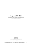
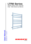
LTR4-512 LTR8-512 LTR8-512M MASTER CLOCK User’s Guide THIS EQUIPMENT COMPLIES WITH FCC CLASS-B REQUIREMENTS PURSUANT SUBPART J OF PART-15 This device complies with Part 15 of the FCC Rules. Operation is subject to the following two conditions: (1) this device may not cause harmful interference, and (2) this device must accept any interference received, including interference that may cause undesired operation. WARNING: Changes or modifications to this product not expressly approved by the party responsible for compliance could void the user’s authority to operate this equipment. NOTE: This equipment has been tested and found to comply with the limits for a Class B digital device, pursuant to Part 15 of the FCC Rules. These limits are designed to provide reasonable protection against harmful interference in a residential installation. This equipment generates, uses, and can radiate radio frequency energy and, if not installed and used in accordance with the instructions, may cause harmful interference to radio communications. However, there is no guarantee that interference will not occur in a particular installation. If this equipment does cause harmful interference to radio or television reception, which can be determined by turning the equipment off and on, the user is encouraged to try to correct the interference by one or more of the following measures: - Reorient or relocate the receiving antenna. - Increase the separation between the equipment and receiver. - Connect the equipment into an outlet on a circuit different from that to which the receiver is connected. - Consult the dealer or an experienced radio TV technician for help. This Class B digital apparatus complies with Canadian ICES-003. Cet appareil numerique de la classe B est conforme a la norme NMB-003 du Canada. LTR4-512 LTR8-512 LTR8-512M MASTER CLOCK LATHEM TIME CORP Document #USG0013F 08-27-2003 “LTR4-512”, “LTR8-512”, “LTR8-512M”, “Radio Sync”, “LTR MasterLink”, “Terminal Manager” and “PayClock” are Trademarks of Lathem Time Corp., Atlanta, GA USA MS-DOS and Windows® are registered trademarks of Microsoft Corporation. Other product names mentioned in this manual may be trademarks of their respective companies and are hereby acknowledged. © 2000 LATHEM TIME CORP Printed in USA TABLE OF CONTENTS WELCOME ...........................................................................................................................4 KEYPAD COMMANDS ...........................................................................................................6 Quick Check Command [*] Status ................................................................................................6 Quick Check Command [1] Edit Keys ..........................................................................................6 Quick Check Command [3] 12/24 Hour Display ..........................................................................7 Program Keys ..................................................................................................................................7 [0]=Password ...................................................................................................................................7 [1]=Set Date and Time ....................................................................................................................8 [2]=Select Clock Control.................................................................................................................9 [3]=Manual Bell Control...............................................................................................................10 [4]=Program Schedules.................................................................................................................10 [5]=Schedule Changes...................................................................................................................13 [6]=Enable or Disable Circuits.....................................................................................................13 [7]=Daylight Savings .....................................................................................................................13 [8]=Change Schedule ....................................................................................................................14 [9]=Sync Clocks .............................................................................................................................14 [A]=Program Holidays..................................................................................................................15 [B]=Communications (LTR8-512 and LTR8-512M Only) ........................................................16 [C]=Change Password ..................................................................................................................17 LTRx-512 User’s Guide Welcome Thank you for purchasing your new MASTER CLOCK. You can use your new Master to ring bells or turn on circuits for up to 99 seconds, as well as to synchronize the time on secondary wall clocks or devices. This manual covers 3 models of MASTER clocks: the LTR4-512, the LTR8-512 and the LTR8-512M LTR4-512 LTR8-512 LTR8-512M System Clock Correction 1 correction type running, plus RS485 correction Bell Circuits 4 with no clock correction 2 with 1 clock correction Certifications UL, cUL, PC Interface Software None Up to 2 like or dissimilar correction types running simultaneously, plus RS485 correction 8 with no clock correction 6 with 1 clock correction 4 with 2 clock correction UL, cUL, FCC, DOC (internal modem) RS-232, RS-485 Atomic clock synchronization Remote Schedule selector switch (optional) No No No Yes Up to 2 like or dissimilar correction types running simultaneously, plus RS485 correction 8 with no clock correction 6 with 1 clock correction 4 with 2 clock correction UL, cUL, FCC, DOC (internal modem) RS-232, RS-485, Modem Yes. Requires the MasterLink software Yes If your Master has 4 lights on the front panel, then you have the model LTR4-512 1 2 3 1 2 3 6 4 5 7 8 9 * 0 # 4 CLK 1 cancel ent er If your Master has 8 lights at the left of the front panel, then you have the model LTR8-512. If the TR light at the keypad is lit, then you have the model LTR8-512M 1 2 3 4 5 6 7 8 CLK 2 CLK 1 1 2 3 SD 4 5 6 TR 7 8 9 RD * 0 # CD cancel 4 ent er LTRx-512 User’s Guide Your Master contains a lithium battery to keep the correct time when power has stopped due to an outage or the internal on/off switch. Once AC power resumes, your Master will calculate how much time your clocks lost and will automatically advance them to the correct time (this feature does not support Clock Types 14, 15 or 24). The list below describes the functions that you can set for your Master: • Passwords • Date and time • Clock types to sync • Manual bell control (example: sounding a fire alarm) • Bell schedules (with events lasting up to 99 seconds) • Dates when automatic schedule changes go into effect • Manual circuit disabling (example: for safety during maintenance) • Daylight savings time features • Instant bell schedule changes • Instant clock synchronization • Holiday schedules • Communications when using the LTR MasterLink software with your Master, an RS-485 network or modem access (available on the LTR8-512 and LTR8-512M only) Normal Display DA M M DD YY You see the time on the clock display, as well as the Month, Date and Year (shown as ‘MM’, ‘DD’, and ‘YY’ above). If you set your Master to display time in 24-hour format, ‘DA’ shows the day of the week: SU, MO, TU, WE, TH, FR, SA or HO (Holiday). If you set your Master to display time in 12-hour format, ‘DA’ shows AM or PM You can enter program your Master by pressing the [#] key when you see the normal time display on the Master. When you see SELECT FUNCTION CODE, you can start programming. Note that the Master resets its display back to the time if you have not pressed a key for 5 minutes 5 LTRx-512 User’s Guide Keypad Commands Quick Check Command [*] Status This “Quick Check” command displays system information for about two (2) seconds Any time you see the time and date displayed, you can press [*] to see the Master status. You will see the firmware version, terminal ID#, communications baud rate, time display format (12-hr or 24-hr), daylight savings country code and the clock types set with your system When you press [*], you will see a display similar to 04-03-03 ID# 065 | TIME 12HR | CLK1 01 | VER.2.11 BAUD 9600 DST 08 CLK2 00 Display Description V1.06 Firmware version ID# Terminal ID# ** BAUD Baud rate for network communications ** TIME Shows if display is in 12-hr or 24-hr format DST Daylight savings time country code CLK1 | CLK2 Clock types that will synchronize ** (LTR8-512 & LTR8-512M only) If you need to call Tech Support, please have the above information available, as well as the serial number of the unit Quick Check Command [1] Edit Keys This “Quick Check” command displays system information for about two (2) seconds Any time you see the time and date displayed on the Master, you can press [1] to see the edit key descriptions. You can use the edit keys to program Bell Schedules, Automatic Schedule Change Dates, and Holiday Dates. When you press [1], you will see 6 LTRx-512 User’s Guide EDITING COMMANDS [1] EDIT [*] ABORT/EXIT [3] PRV [#] NXT/ENTER [6] ADD [4] DEL [9] FIRST Display [1] EDIT [3] PRV [4] DEL [6] ADD [9] 1ST [#] NXT [*] EXIT Description Edit the displayed record Show the Previous record Delete the displayed record Add a new record Show the 1st record (in ascending time order) Show the next record End and exit Quick Check Command [3] 12/24 Hour Display Any time you have entered your password and you see the time and date on the Master, you can press [3] to toggle the time and date between 12-hour and 24-hour format. The 12-hour format shows AM or PM, while the 24-hour format shows the day of the week. Program Keys To program your Master, press the [#] key. As described below, some functions require a user password, and advanced functions require an administrator password. [0]=Password You must enter a password to use most programming functions. To enter your password, press [#][0][#] PASSWORD 000000 Enter your 6-digit password, then press [#] The default user password is 000000. See Function [C] Change Password to learn how to change your user password If you enter the wrong password, you will see ‘INVALID PASSWORD’, and you can try again Once you enter your password, the display shows ‘PASSWORD ACCEPTED’ and then reverts to showing the time. You can now program your Master. If you stop using the keypad for 5 minutes, you must enter your password again to keep programming You must use an administrator password for advanced functions. Functions that require the Administrator Password are [2] Select Clock Ctrl, [6] Disable Circuits, [7] Daylight Savings and [B] Communications. Contact your dealer to learn more about these functions 7 LTRx-512 User’s Guide [1]=Set Date and Time To set the date and time, enter your password (#0#), then [#][1][#] Enter the numbers for the month, date and year (4-digit year), then press [#], such as [0][4][0][3][2][0][0][3][#] shown below: ENT.DATE: 04-03-2003 ENTER DAY-OF-WEEK: D 1=SUNDAY..7=SATURDAY Enter a number [1] - [7] for the day of the week, Sunday through Saturday: [1]=Sunday [2]=Monday [3]=Tuesday [4]=Wednesday [5]=Thursday [6]=Friday [7]=Saturday For example, if you press [5], the display shows ENT.DATE: 04-03-2003 TODAY IS THURSDAY ENTER TIME: HH:MM SELECT [0]PM / [1]AM Press [#] to confirm or [*] to try again Once you press [#], enter the time of the next upcoming minute, using either 12-hour or 24-hour format, then press [#]. (If using 24-hour format, enter midnight as 00:00) For example, if the current time is 08:59, enter: 09:00 ENT.DATE: 04-03-2003 TODAY IS THURSDAY ENTER TIME: 09:00 SELECT [0]PM / [1]AM If you enter a time less than 13:00 (1:00 PM), then you will see SELECT [0]PM / [1]AM Press [0] for PM or [1] for AM. If you choose ‘PM’, then the time will display in 24-hour format to confirm your entry 8 LTRx-512 User’s Guide ENT.DATE: 04-03-2003 TODAY IS THURSDAY ENTER TIME: 21:00 PRESS [#] IF CORRECT Press the [#] key at the top (‘00’ seconds) of the new minute to accept. If the time or date is not correct, press [*] to cancel and try again. The display will now show the time and date you just entered. You can toggle between the 12-hour and 24-hour display using “Quick Check” command [3] Make sure you enter the correct date and day, because the schedules you setup depend on these choices [2]=Select Clock Control This function requires the administrator password Use this function to choose the make/model of the clocks that your Master will synchronize (Note: The LTR4-512 can only synchronize one type of secondary system) Enter your administrator password, then start this function by pressing [#][2][#] ENABLE CLOCK CIRCUIT SELECT CLK1 CODE: NN [#] FOR CODE LIST Enter the 2-digit code for CLOCK1, then press [#]. If you entered a code other than ‘00’, and you have a LTR8-512 or LTR8-512M, you will see ENABLE CLOCK CIRCUIT SELECT CLK2 CODE: NN [#] FOR CODE LIST Enter the code for CLOCK2, or [0][0] if you will not use a CLOCK2, then press [#] PRESS [#] IF CORRECT Enter [#] to confirm or [*] to cancel and try again 9 LTRx-512 User’s Guide [3]=Manual Bell Control This function does not require a password Use this function to test bell circuits or to sound a bell during an unscheduled time, such as a fire alarm. Press [#][3][#] to start this function MANUAL BELL CONTROLS 1-2-3-4-5-6-7-8 PRESS AND HOLD [#] TO EXECUTE.[*]TO END The 2nd line of the display only shows the circuit numbers (1-8) that are available for bell controls Press [0] to turn them all off, or press keys [1] - [8] to turn a circuit off or on When you see the circuits that you want to ring, press and hold the [#] key. The green front panel lights will light up to show that you have turned on those relays. Release the [#] key to turn those relays back off. Note that the relays scheduled to turn ‘on’ will cycle as programmed You can now sound other circuits, or press [*] to quit Note: When your CLOCK1 Type is Type 14 (Electronic Coded) or Type 15 (Straight Frequency), you may need to hold the [#] key for about a minute to energize your bell circuits. You will know that your circuits have turned on when the green front panel lights for those circuits light up [4]=Program Schedules Use this function to set bell schedules. A schedule lists the days and times when the bell circuits will turn on. Your Master can have up to eight (8) different bell schedules with up to sixty-four (64) ‘events’ per schedule. If needed, you can make several schedules active at the same time to increase the number of events to as many as 512 (8 multiplied by 64). In fact, each ‘event’ can trigger several ‘actions’. For example, you can program a single event to turn on relays #1, #2 and #4 for 7 seconds at 08:00 AM on Tuesdays, Thursdays and Holidays Enter your password (#0#), then press [#][4][#] to start programming schedules SCHEDULE PROGRAMMING SELECT SCHEDULE # N 10 LTRx-512 User’s Guide Press Schedule Number [1] - [8]. Normally, start with [1] The following will show on the display: For Firmware version 4.05 and earlier: For Firmware version 4.06 and later: To select the appropriate mode: Press [1] DATA ENTRY to create a new schedule Press [2] DATA SCAN to view a schedule Press [3] DATA EDIT to change a schedule Press [4] CLEAR to clear all records in the selected schedule When you choose [2] DATA SCAN, you can view events. You can use these scan keys: Scan Key [9] 1ST [3] PRV [#] NXT [*] EXIT Description Go to the 1st event (in ascending time order) View the previous event View the next event End and exit When you choose [3]DATA EDIT, you can view, edit or delete events. You can use the keys above, plus these edit keys: Edit Key [1] EDIT [4] DEL [6] ADD Description Edit the displayed event Delete the displayed event Add a new event When you choose [1]DATA ENTRY, you can create a schedule. Follow the steps below to create a schedule SELECTED SCHEDULE # 1 SELECTED MODE = ENTRY ZONE TYPE = BELL PRESS [#] TO EXECUTE 11 LTRx-512 User’s Guide Press [#] to accept. Then select the days when this event occurs [0] selects no days, [1]-[7] selects Sunday-Saturday, [8] selects holidays and [9] selects all days (including holidays). Press these keys to turn days on or off. After you choose the days when the event will occur, press [#] Example: Press 1,3,5,7,8 to turn off all days except Monday, Wednesday and Friday SELECT DAYS: S M T W T F S H 2 4 6 Select which circuits will turn on for this event Example: Press 1,2,3,4, to turn on circuits 1, 2, 3 and 4 ACTIVE DAYS: M W F SELECT CKTS: 1234 Enter the event start time in 12-hour or 24-hour format. If you enter a time earlier than 13:00 (1:00 PM), then press [1] to change PM to AM ACTIVE DAYS: M W F SELECT CKTS: 1234 ENTER START: HH:MM P The menu will ask for the bell length (SECONDS ON) ACTIVE DAYS: M W F SELECT CKTS:1234 START TIME : 08:00 A SECONDS ON : 03 Enter how many seconds this event lasts. The bell length shows 3 seconds (or 5 seconds if your CLOCK1 is Type 15). To accept, press [#], or enter another value from 01-99 seconds, then press [#] Your Master saves these values in the schedule then displays SELECT DAYS again, waiting for you to enter another event. Once you finish entering events, you can quit by pressing [*] Make sure you use Function 5 or Function 8 to activate your schedules Use the handy programming charts included with your Master Clock 12 LTRx-512 User’s Guide [5]=Schedule Changes If you wish to activate schedules at a future date, use Schedule Changes to program a schedule’s start date and time. This function works much like the Bell Schedule Function [4]. Enter your password (#0#), then press [#][5][#] PROG.SCHEDULE CHANGE SELECT [1]DATA ENTRY [2]DATA SCAN [3]DATA EDIT After making your choice, you will see PROG.SCHEDULE CHANGE EFF. DATE : 00-00-00 EFF. TIME : 00:00 NEW SCHEDS: Enter the date and time, then press the schedule number (1-8) for each schedule to activate at that date and time. You do not need to press [#] after you enter each value - only press [#] after entering the last New Schedule on line 4. After you enter each change, the menu gives you the chance to enter, scan or edit another one. Or, press [*] to quit. The Master will hold up to 16 programmed changes. Once your change occurs, your Master clears it from memory, making room for you to enter more changes. Note: Only the schedules entered in this function will activate at the Date and Time entered. Any schedules previously active will become deactive if not on the list of new schedules. [6]=Enable or Disable Circuits This function requires the administrator password. Use this function to Enable and Disable your Master’s control relays during circuit wiring or maintenance. This function can also ‘hold back’ clocks to manually adjust for daylight savings in the fall if you have chosen not to use Function 7 “Daylight Savings”. [7]=Daylight Savings This function requires the administrator password. 13 LTRx-512 User’s Guide Your LTRx-512 knows the daylight savings time (DST) settings for over 75 countries. By using the 2-digit “country code”, your LTRx-512 will automatically adjust for daylight savings time. If you own the LTR8-512 or LTR8-512M and if your nation does not appear in the Country Code list or if the dates for Daylight Savings in your country have changed, you can choose code ‘00’ and use the optional LTR MasterLink software to program when the clock adjustments should occur. [8]=Change Schedule Use this function to run a schedule that you setup in function [4]=PROGRAM SCHEDULE. Enter your password (#0#), then press [#][8][#] to change a schedule. You will see a display similar to the following: ACTIVATE SCHEDULE(S) ACTIVE NOW:12 5 ACTIVE NEW: In the above example, the display shows that Schedules #1, #2 and #5 are all active now. You can think of this as 3 schedules of up to 64 events used together to make 1 large schedule of up to 192 events Press [1] - [8] to select the schedules you wish activated immediately. The [0] key turns all schedules off. When the ACTIVE NEW line shows the schedules that you want active, press [#]. Be sure that all schedules that you want active show on this line, even if they were already active. You will see PRESS [#] TO EXECUTE Press [#] again, and your choices on ACTIVE NEW will activate now. Or, press [*] to cancel without making any changes Schedules that you make active here will stay active until you change them again or until the Date and Time of the next Schedule Change [5] is to occur. [9]=Sync Clocks Use this function to quickly sync any secondary clocks that lose time. This can occur if power to your LTRx-512 stayed on while power to the secondary clocks stopped. Note: This function is primarily used during initial installation of the secondary system, if there has been maintenance of the system requiring the power to be turned off, or other special circumstance. The Master Clock should keep your secondary clocks on time based on the type and style of correction the system is using. 14 LTRx-512 User’s Guide Enter your password (#0#), then press [#][9][#]. You will see a display similar to the following: SELECT SYNCH CLOCKS CLK[1] &/OR CLK[2] Note: CLK[2] appears on the LTR8-512 and LTR8-512M only Since only one of the clock circuits may have lost power, you can choose to re-sync CLOCK1, CLOCK2 or both. Press [1] to turn on or off this display: ADVANCE CLK1 Press [2] to turn on or off this display (you will see this option only if your clock is setup for 2 Clock Systems.): ADVANCE CLK2 After choosing which clock circuits to sync, press [#]. If your clocks are synchronous types (01, 03, 06, 18, 19 & 22), they can only advance to the start of the nearest hour and will then wait for the Master Clock to catch up. If your clocks are impulse types, then you will see Enter the time shown on the secondary clocks that have lost time, then press [#]. You will see PRESS [#] TO EXECUTE To sync the secondary clocks, press [#], or press [*] to cancel. Your impulse clocks will advance to your LTRx-512’s time NOTES: 1. The Clock Sync function does not support Clock Types 14, 15 or 24 2. When a Power-On Clock Recovery or user-initiated clock sync occurs, your LTRx-512 will not accept other commands to start clock synchronization 3. You can cancel Power-On Clock Recovery or user-initiated clock synchronization by choosing Clock Types again through function [2]=SELECT CLOCK CTL. [A]=Program Holidays You can enter up to 16 dates as holidays in your LTRx-512. During holidays, only the events that you set to occur on holidays will turn on when they reach the scheduled time. Examples: 15 LTRx-512 User’s Guide 1) Select SmtwtfSH for an event to occur on Sunday, Saturday, or any day setup as a Holiday, even if the holiday is other than Sunday or Saturday 2) Select sMTWTFsh for an event to occur Monday through Friday, unless the day is a holiday 3) Select SMTWTFSH for an event to occur every day, even on holidays You cannot choose function [A] directly. To start the Program Holidays function, enter your password (#0#), then press [#][9][0][#] Use [1] to enter new holidays, [2] to view holidays and [3] to change or delete holidays HOLIDAY PROGRAMMING SELECT [1]DATA ENTRY [2]DATA SCAN [3]DATA EDIT If you choose [1], you will see Use keys [1] - [9] to enter a holiday in MM-DD-YY format, then press [#] to accept, or [*] to cancel HOLIDAY PROGRAMMING SELECTION MODE=ENTRY SELECT DATE ??-??-?? The menu will now ask for another holiday. You can do so or press [*] to finish Once your holiday occurs, your Master clears it from memory, making room for you to enter more holidays [B]=Communications (LTR8-512 and LTR8-512M Only) This function requires the administrator password Use this function if you use LTR MasterLink or Terminal Manager software with your LTR8-512 You cannot choose function [B] directly. To enter Communications, press [#][9][0][0][#] Use this function to enter the data transmission speed and terminal ID# You must enter these same settings for your LTR8-512 in the LTR MasterLink software 16 LTRx-512 User’s Guide You can see your terminal ID# and baud rate by using the “Quick Check” command [*] when the LTR8-512 is in Clock Mode [C]=Change Password Use this function to change the default user password (000000) to a unique 6-digit number to prevent unauthorized access to the LTRx-512’s programming functions. You should keep a copy of this password in a safe place You cannot choose function [C] directly. To start the Change Password function, enter your current password, then press [#][9][0][0][0][#] NEW PASSWORD 000000 To keep your old password, press [*] to cancel To change the password, enter a 6-digit number, then press [#]. You will see PRESS [#] IF CORRECT Press [#] to accept, or press [*] to cancel and try again Once you change your password, your LTRx-512 will no longer accept the old password You can always change your password again if needed 17 LTRx-512 User’s Guide FOR UNITS EQUIPPED WITH AN INTERNAL MODEM NOTICE: This equipment complies with Part 68 of the FCC Rules. A label is affixed to the mounting panel of this equipment containing, among other information, its FCC Registration Number and Ringer Equivalence Number (REN). If requested, provide this information to your Telephone Company. The registration jack USOC for this equipment is (RJ-11). An FCC compliant telephone cord and modular plug is provided with this equipment. This equipment is designed to connect to the telephone network or premises wiring using a compatible modular jack, which is Part 68 compliant. See installation instructions for details. The REN is useful to determine how many devices can connect to the telephone line. Excessive RENs on the telephone line may result in the devices not ringing in response to an incoming call. In most areas, the sum of “REN” of all devices should not exceed five (5). Contact your local Telephone Company to find out the exact number of devices that can connect to a line, as determined by the total “REN”. If your telephone equipment (Modem) harms the telephone network, the Telephone Company will notify you in advance that temporary discontinuance of service may be required, but if advance notice isn’t practical, they will notify you as soon as possible. You will be advised of your right to file a complaint with the FCC if you believe it is necessary. Your Telephone Company may make changes in its facilities, equipment, operations or procedures that could affect the operation of your equipment. If they do, they will notify you in advance so as to give you an opportunity to maintain uninterrupted service. If you experience trouble with this equipment (Modem), please contact Lathem Time Customer Service at (800) 241-4990 for repair/warranty information. If your equipment is causing harm to the telephone network, the Telephone Company may request that you disconnect the equipment until the problem is resolved. A Lathem-Authorized Service Center will replace a defective Lathem Modem product. This equipment may not be used on public coin service provided by the Telephone Company. Connection to party lines is subject to state tariffs. (Contact your state public utility commission or corporation commission for information.) NOTICE: The Industry Canada label identifies certified equipment. This certification means that the equipment meets certain telecommunications network protective, operational and safety requirements. The Industry Canada does not guarantee the equipment will operate to the user’s satisfaction. Before installing this equipment, users should ensure that it is permissible to be connected to the facilities of the local Telecommunications Company. This equipment must also be installed using an acceptable method of connection. In some cases, the company’s inside wiring associated with a single line individual service may be extended by means of a certified connector assembly (telephone extension cord). The customer should be aware that compliance with the above conditions may not prevent degradation of service in some situations. Any equipment repairs made by the user, or equipment malfunctions, may give the Telecommunications Company cause to request the user to disconnect the equipment. Users should ensure, for their own protection, that the electrical ground connections of the power utility, telephone lines and internal metallic water pipe system, if present, are connected together. This precaution may be particularly important in rural areas. Caution: Users should not attempt to make such connections themselves, but should contact the appropriate electric inspection authority, or electrician, as appropriate. NOTE: The Ringer Equivalence Number (REN) assigned to each terminal device provides an indication of the maximum number of terminals allowed to be connected to a telephone interface. The termination of an interface may consist of any combination of devices subject only to the requirement that the sum of the Ringer Equivalence Numbers of all the devices does not exceed 5. A NOTE ABOUT THE LITHIUM BATTERY The Lithium Battery (coin cell) contained in this product is NOT user replaceable. When replaced by an authorized Service Center, used batteries should be disposed of according to the manufacturer’s instructions. 18 LTRx-512 User’s Guide Limited One-Year Limited Warranty Lathem warrants the hardware products described in this guide against defects in material and workmanship for a period of one year from date of original purchase from Lathem or from an authorized Lathem reseller. The conditions of this warranty and the extent of the responsibility of Lathem Time Corporation (“Lathem”) under this warranty are listed below. 1. 2. 3. 4. 5. 6. 7. 8. 9. This warranty will become void when service performed by anyone other than an approved Lathem warranty service dealer results in damage to the product. This warranty does not apply to any product which has been subject to abuse, neglect, or accident, or which has had the serial number altered or removed, or which has been connected, installed, adjusted, or repaired other than in accordance with instructions furnished by Lathem. This warranty does not cover dealer labor cost for removing and reinstalling the machine for repair, or any expendable parts that are readily replaced due to normal use. The sole responsibility of Lathem under this warranty shall be limited to repair of this product, or replacement thereof, at the sole discretion of Lathem. If it becomes necessary to send the product or any defective part to Lathem or any authorized service dealer, the product must be shipped in its original carton or equivalent, fully insured with shipping charges prepaid. Lathem will not assume any responsibility for any loss or damage incurred in shipping. WARRANTY DISCLAIMER AND LIMITATION OF LIABILITY: Except only the limited express warranty set forth above, the products are sold with no expressed or implied warranties of any kind, and the implied warranties of merchantability and fitness for a particular purpose are hereby expressly disclaimed. No warranties are given with respect to products purchased other than from Lathem or an authorized Lathem reseller and any such products are purchased "as is, with all faults." In no event will Lathem be liable for any direct, indirect, special, incidental or consequential damages arising out of or in connection with the delivery, use or inability to use, or performance of this product. In the event any limited remedy given herein shall be deemed to have failed of its essential purpose, Lathem's maximum liability shall be to refund the purchase price upon return of the product. Proof of date of purchase from Lathem or an authorized Lathem reseller is required for warranty service on this product. This Warranty grants specific legal rights. Additional legal rights, which may vary by locale, may also apply. Should any difficulties arise with the performance of this product during warranty, or with any Lathem authorized service centers, contact Lathem Time at the address below. Lathem Time 200 Selig Drive, SW, Atlanta, GA 30336 404-691-0405 www.lathem.com Copyright © 2003 Lathem Time Corporation. All rights reserved. 19 LTRx-512 User’s Guide H Holiday schedules......................................5, 6, 10, 16 I Impulse type clocks .................................................15 L Lights.......................................................................10 LTR MasterLink ............................................5, 14, 16 M Manual bell control....................................................5 P Passwords .................. 5, 7, 8, 9, 10, 13, 14, 15, 16, 17 Program Holidays function......................................15 Program Keys ............................................................7 Q Quick Check Command [*] .......................................6 Quick Check Command [1] .......................................6 Quick Check Command [3] .......................................7 R RS-485 network...................................................5, 16 S Schedule Changes function......................................13 Schedules.....................................9, 10, 13, 14, 21, 22 Set the date and time..................................................8 Sync Clocks function...............................................14 Synchronous clock types .........................................15 T Terminal ID# .................................................6, 16, 17 Test circuits .............................................................10 U User password .....................................................7, 17 B Baud rate..............................................................6, 17 Bell schedules..................................................5, 6, 10 Bell Zones................................................................21 C Change Password ................................................7, 17 Change Schedule .....................................................14 Clock types ................................................................6 Communications......................................2, 5, 6, 7, 16 Communications function........................................16 Country code .......................................................6, 14 D Daylight savings ........................................5, 6, 13, 14 Disable circuits ....................................................7, 13 E Enable circuits .........................................................13 F Function [0] - Password.............................................7 Function [1] - Set Date and Time ..............................8 Function [2] - Select Clock Control...........................9 Function [3] - Manual Bell Control .........................10 Function [4] - Program Schedules ...........................10 Function [5] - Schedule Changes.............................13 Function [6] - Enable/Disable Circuits ....................13 Function [7] - Daylight Savings ..............................13 Function [8] - Change Schedule ..............................14 Function [9] - Sync Clocks ......................................14 Function [A] - Program Holidays ............................15 Function [B] - Communications ..............................16 Function [C] - Change Password .............................17 20 LTRx-512 User’s Guide BELL SCHEDULE PROGRAMMING CHART SCHEDULE #: 1 2 3 4 5 6 7 8 REC No. Ex. DAYS SMSTWTFSH MTWTF CIRCUITS 12345678 1234 START HH:MM 08:00 (Circle One) DUR SS 5 REC No. Ex. 01 33 02 34 03 35 04 36 05 37 06 38 07 39 08 40 09 41 10 42 11 43 12 44 13 45 14 46 15 47 16 48 17 49 18 50 19 51 20 52 21 53 22 54 23 55 24 56 25 57 26 58 27 59 28 60 29 61 30 62 31 63 32 64 DATE:____-____-____ DAYS SMSTWTFSH MTWTF CIRCUITS 12345678 1234 START HH:MM 08:00 COPY THIS PAGE FOR USE IN CREATING YOUR OWN BELL SCHEDULES DUR SS 5 LTRx-512 User’s Guide SCHEDULE CHANGE DATES PROGRAMMING CHART DATE:____-____-____ REC NO. MM Ex. 06 DATE DD YY 02 03 TIME HH MM 07 00 SCHEDULES 12345678 2345 COMMENTS Shortened Schedule 01 02 03 04 05 06 07 08 09 10 11 12 13 14 15 16 COPY THIS PAGE TO USE IN CREATING YOUR SCHEDULE CHANGE TABLE LTRx-512 User’s Guide HOLIDAYS SETUP CHART DATE:____-____-____ RECORD NO. MM Ex. 07 DATE DD 04 YY 03 COMMENTS Independence Day 01 02 03 04 05 06 07 08 09 10 11 12 13 14 15 16 COPY THIS PAGE TO USE IN CREATING YOUR HOLIDAY TABLE