1
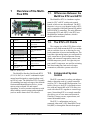
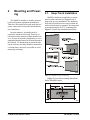
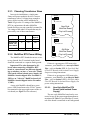
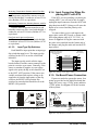
026-1706 Rev 1 10-29-02
MultiFlex RTU Rooftop
Controller Installation and
Operation Manual
1640 Airport Road, Suite 104
Kennesaw, GA 31044
Phone: (770) 425-2724
Fax: (770) 425-9319
ALL RIGHTS RESERVED.
The information contained in this manual has been carefully checked and is believed to be accurate. However, Computer Process Controls, Inc. assumes no responsibility for any inaccuracies that may be contained herein. In no event will
Computer Process Controls, Inc. be liable for any direct, indirect, special, incidental, or consequential damages resulting
from any defect or omission in this manual, even if advised of the possibility of such damages. In the interest of continued
product development, Computer Process Controls, Inc. reserves the right to make improvements to this manual, and the
products described herein, at any time without notice or obligation.
READ ALL INSTRUCTIONS CAREFULLY
If the equipment is not used in the manner specified by the manufacturer, the protection provided
by the equipment may be impaired.
SAVE THIS INSTRUCTION MANUAL
This instruction manual contains important operating instructions for the MultiFlex RTU rooftop
control board.
Table of Contents
1 OVERVIEW OF THE MULTIFLEX RTU ................................................................................................................ 1
1.1. DIFFERENCES BETWEEN THE MULTIFLEX RTU AND ARTC ....................................................................................... 1
1.2. THE RTU’S I/O POINTS ................................................................................................................................................ 1
1.3. INDEPENDENT SYSTEM CONTROL ................................................................................................................................ 1
2 MOUNTING AND POWERING ................................................................................................................................. 2
2.1. SNAP-TRACK INSTALLATION ........................................................................................................................................
2.2. THE PLUG-IN OUTPUT BOARD .....................................................................................................................................
2.3. POWERING THE MULTIFLEX RTU BOARD ...................................................................................................................
2.3.1. Choosing Transformer Sizes .................................................................................................................................
2.3.2. MultiFlex RTU Power Wiring...............................................................................................................................
2
3
3
4
4
2.3.2.1. New-Style MultiFlex RTU Boards (with Isolated Power Supply) ..................................................................................... 4
2.3.2.2. Old-Style MultiFlex RTU Boards No Isolated Power Supply) .......................................................................................... 5
2.3.3. Wire Types and Maximum Distances.................................................................................................................... 6
2.4. THE MULTIFLEX RTU BATTERY AND BATTERY ENABLE JUMPER ............................................................................. 7
3 THE I/O NETWORK .................................................................................................................................................... 8
3.1. WIRING TYPES .............................................................................................................................................................. 8
3.1.1. Daisy Chains ......................................................................................................................................................... 8
3.1.2. Network ID Numbers ............................................................................................................................................ 8
3.1.2.1. Numbering the MultiFlex RTU .......................................................................................................................................... 9
3.1.3. Setting the Baud Rate............................................................................................................................................ 9
3.1.4. Setting the Terminating Resistance Jumpers ........................................................................................................ 9
4 RTU INPUT AND OUTPUT SETUP......................................................................................................................... 10
4.1. THE INPUTS.................................................................................................................................................................
4.1.1. MultiFlex RTU Fixed Input Locations ................................................................................................................
4.1.2. Auxiliary Input Types ..........................................................................................................................................
4.1.3. Wiring Sensors to the MultiFlex RTU.................................................................................................................
10
10
10
11
4.1.3.1. Wiring ............................................................................................................................................................................... 11
4.1.3.2. Sensor Wiring Types ........................................................................................................................................................ 11
4.1.3.3. Input Type Dip Switches .................................................................................................................................................. 12
4.1.4. Input Connection When Replacing ARTC with RTU .......................................................................................... 12
4.1.5. On-Board Power Connection.............................................................................................................................. 12
4.1.5.1. Current Ratings for On-Board Power Sources ................................................................................................................. 13
4.1.5.2. Powering Sensors Requiring 24VAC Off the Power Transformer................................................................................... 13
4.2. THE OUTPUTS .............................................................................................................................................................
4.2.1. MultiFlex RTU Fixed Outputs.............................................................................................................................
4.2.2. MultiFlex RTU Auxiliary Output Types ..............................................................................................................
4.2.3. Wiring Outputs to Points.....................................................................................................................................
4.2.4. Output Fail-Safe Dip Switches............................................................................................................................
4.2.5. Relay Output Ratings and Fuse Protection.........................................................................................................
4.3. ANALOG OUTPUTS ......................................................................................................................................................
4.3.1. Wiring the RTU Analog Output Points ...............................................................................................................
13
13
14
14
15
15
16
16
5 BOARD STATUS LEDS ............................................................................................................................................. 17
5.1. STATUS LED .............................................................................................................................................................. 17
5.2. TX AND RX LEDS ...................................................................................................................................................... 17
5.3. THE CODE A LED ...................................................................................................................................................... 17
Table of Contents
MultiFlex RTU Operator’s Guide • v
5.4. THE CODE B LED ...................................................................................................................................................... 18
5.5. RELAY OUTPUT LEDS ................................................................................................................................................ 18
6 SOFTWARE OVERVIEW ......................................................................................................................................... 19
6.1. INTRODUCTION TO ZONE CONTROL............................................................................................................................ 19
6.2. TEMPERATURE CONTROL ........................................................................................................................................... 19
6.2.1. Set Points............................................................................................................................................................. 19
6.2.1.1. Set Point Dead Bands ....................................................................................................................................................... 19
6.2.1.2. Stage ON and OFF Delays................................................................................................................................................ 19
6.2.1.3. Summer/Winter and Occupied/Unoccupied Set Points .................................................................................................... 19
6.3. FAN CONTROL ............................................................................................................................................................ 20
6.4. DEHUMIDIFICATION AND HUMIDIFICATION CONTROL ............................................................................................... 20
6.4.1. Dehumidification Control ................................................................................................................................... 20
6.4.2. Humidification Control ....................................................................................................................................... 20
6.5. ECONOMIZATION......................................................................................................................................................... 20
6.5.1. Analog Economizers............................................................................................................................................ 21
6.6. CURTAILMENT ............................................................................................................................................................ 21
6.7. REVERSING VALVE CONTROL .................................................................................................................................... 21
6.8. STAND-ALONE OPERATION ........................................................................................................................................ 21
6.9. SENSOR FAILURES ...................................................................................................................................................... 22
7 THE MULTIFLEX RTU HAND-HELD INTERFACE........................................................................................... 23
7.1.
7.2.
7.3.
7.4.
RTU HAND-HELD TERMINAL STATUS SCREENS........................................................................................................ 23
RTU MAIN MENU....................................................................................................................................................... 24
STATUS MENU ............................................................................................................................................................ 24
CONTROL MENU ......................................................................................................................................................... 25
vi • MultiFlex RTU Operator’s Guide
026-1706 Rev 1 10-29-02
1
Overview of the MultiFlex RTU
1.1.
Differences Between the
MultiFlex RTU and ARTC
The MultiFlex RTU is a hardware replacement for CPC’s ARTC rooftop unit control
boards, which are now discontinued. The RTU
firmware is in every way identical to the ARTC,
and is compatible with both Einstein BX and the
REFLECS BCU controllers. The only difference
between the RTU and ARTC is the RTU uses
the MultiFlex hardware platform, which is
smaller and more robust.
LEGEND
1
INPUT POWER
(24VAC)
9
RS485 I/O TERMINATION JUMPERS
2
RS485 I/O NETWORK
10
HAND-HELD TERMINAL JACK
3
RTU INPUTS 1-8
11
RELAY OUTPUT CONNECTORS
4
RTU INPUTS 9-16 (NOT
ACTIVE FOR RTU)
12
RELAY OUTPUT FUSES
(2A rated, 250V slowblow)
5
NETWORK ID DIP
SWITCHES (S3, S4)
13
RELAY STATUS LEDs
6
INPUT TYPE DIP
SWITCHES (S1, S2)
14
OUTPUT FAIL-SAFE
SWITCHES
7
BOARD STATUS LEDs
(Code A, Code B, General
Status)
15
ANALOG OUTPUTS (#1
and #2 active for RTU, #3
and #4 inactive)
8
DC POWER OUTPUTS
(3 at +5VDC, 1 at
+12VDC)
16
NETWORK STATUS
LEDs
1.2.
The RTU’s I/O Points
The compact size of the RTU allows technicians to easily field-mount the RTU in a rooftop
unit or enclosure close to it, allowing for easy
local connection of sensors and transducers. The
board has eight analog inputs, pre-configured for
quick connection to space temperature sensors,
supply and return air temperature sensors, and
fan and compressor proofs. Its eight relay outputs, rated 2.0 amps max, are used for activating
and deactivating fans, heat and cool stages,
economizers, and other systems or devices.
Table 1-1 - MultiFlex RTU
The MultiFlex Rooftop Unit Board (RTU)
(P/N 810-3062) is a “smart” combination input/
output board designed to control package rooftop HVAC units. The MultiFlex RTU is capable
of controlling heat and cool stages, fans, humidification and dehumidification devices, economizers using on-board I/O and control
algorithms, as well as monitor and interact with
other building control systems and peripherals
(such as smoke alarms and CO2 sensors).
1.3.
Independent System
Control
The RTU can control a rooftop unit independently without the need of a central controller
(such as CPC’s Einstein BX Refrigeration Controller). However, the RTU is designed to interface with an Einstein BX or BCU to allow it to
work with other RTUs together to control large
zones. Networking RTU to a central controller
also allows you to view status on Einstein &
UltraSite32 status screens, report alarms, and
control dehumidification.
The RTU’s configuration can be programmed either with a CPC Hand-Held Terminal (HHT) or through the Einstein front panel.
Differences Between the MultiFlex RTU and ARTC
Overview of the MultiFlex RTU • 1
2
Mounting and Powering
The MultiFlex boards are usually mounted
by the refrigeration equipment manufacturer.
Therefore, the installer need only make the necessary connections between the boards and the
site controller(s).
2.1.
Snap-Track Installation
MultiFlex boards not supplied in a custom
panel or other enclosure are supplied with a
snap-track for easy installation. The insulation
sheet and I/O board must be removed from the
track before the track is mounted. The snap-track
is mounted using the 0.1875” mounting slots.
Figure 2-1 shows this installation procedure.
In some instances, an installer may be
required to mount an I/O board. There are no
restrictions on the location of these boards; however, for ease of network configuration, it is recommended that the boards be located adjacent to
the Einstein. I/O boards may be mounted without an enclosure, but they should be mounted in
a location that is not easily accessible to avoid
tampering or damage.
Figure 2-1 - MultiFlex Snap-Track Mounting
Figure 2-2 provides mounting dimensions
for the MultiFlex board.
Figure 2-2 - MultiFlex Board Dimensions
2 • MultiFlex RTU Operator’s Guide
026-1706 Rev 1 10-29-02
2.2.
The additional board makes the MultiFlex
RTU boards considerably taller than the MultiFlex 16 and other CPC I/O boards. If you will be
mounting these boards in an enclosure, the board
will need at least 2.5" of clearance between the
base board and the panel door.
The Plug-In Output
Board
2.3.
Powering the MultiFlex
RTU Board
All models of MultiFlex require a 24VAC
Class 2 input power source. The MultiFlex RTU
requires the power source to be non-centertapped.
CPC supplies a wide variety of 24VAC
transformers with varying sizes and either with
or without center taps. Table 2-1 shows the
transformer sizes and whether they are centertapped or non-center-tapped.
Figure 2-3 - Exploded View — MultiFlex RTU
The MultiFlex RTU has an output sub-board
that plugs to the top of the base board. Typically,
these boards are shipped with the output board
pre-installed on the board using stand-offs, so no
additional hardware setup should be necessary.
Xformer P/N
VA Rating
Primary Voltage
Center Tap?
640-0041
50 VA
110 VAC
No
640-0042
50 VA
220 VAC
No
640-0056
56 VA
Multi-tap (120/208/240 VAC)
Yes
640-0050
75 VA
110 VAC
No
640-0045
75 VA
220 VAC
No
640-0080
80 VA
Multi-tap (120/208/240 VAC)
Yes
Table 2-1 - Transformers Compatible with MultiFlex
The Plug-In Output Board
Mounting and Powering • 3
2.3.1. Choosing Transformer Sizes
In most site installations, a single transformer will power multiple devices. Choose a
transformer with a VA rating large enough to
power all devices that will be attached to it.
Table 2-2 gives the VA ratings of the MultiFlex
RTU in conjunction with other MultiFlex
boards. Refer to your site controller’s manual for
VA ratings of the other I/O boards that may be
powered by one of these transformers.
Unit
VA
VAC
24 VAC
POWER LED
New Style
MultiFlex Board
(Top Left Corner)
Center
tapped?
MultiFlex 16
6
24
Yes
MultiFlex 88,
88AO, 168,
and 168AO
15
24
NO
MultiFlex RTU
15
24 VAC
NO POWER LED
24
NO
Old Style
MultiFlex Board
(Top Left Corner)
Table 2-2 - Device Power Requirements
2.3.2. MultiFlex RTU Power Wiring
The MultiFlex RTU boards do not use a center tap. Instead, the 0V terminal on the board
should be connected to a separate Earth ground.
Important! The rules that must be followed when connecting a MultiFlex RTU
board to a transformer are different depending on whether you have a "new style" MultiFlex board with an isolated power supply (all
MultiFlex boards shipped after November 1,
2002) or an "old style" MultiFlex board (all
MultiFlex boards shipped before November
1, 2002).
A new-style MultiFlex board has a green
power LED located next to the 24VAC connection terminal in the upper right corner of the circuit board (see Figure 2-4 for reference).
Figure 2-4 - New-Style vs. Old-Style MultiFlex Board
If there is a green power LED next to the
connector, your MultiFlex is a new-style MultiFlex -- refer to Section 2.3.2.1., New-Style MultiFlex RTU Boards (with Isolated Power Supply)
for power wiring instructions.
If there is no green power LED next to the
connector, your MultiFlex is an old-style MultiFlex -- refer to Section 2.3.2.2., Old-Style MultiFlex RTU Boards No Isolated Power Supply) for
power wiring instructions.
2.3.2.1.
New-Style MultiFlex RTU
Boards (with Isolated Power
Supply)
The new-style MultiFlex board can be connected to any of the center-tapped transformers
mentioned in Table 2-2, provided the 0V terminal of the board is connected to an Earth ground.
4 • MultiFlex RTU Operator’s Guide
026-1706 Rev 1 10-29-02
A center-tapped transformer may power
both center-tapped and non-center-tapped
devices at the same time, as long as none of the
non-center-tapped MultiFlex boards are oldstyle MultiFlex boards. If an old-style MultiFlex shares the same center-tapped transformer
as a device that uses the center tap, the old-style
MultiFlex will be damaged. Figure 2-5 shows
how to wire a non-center tapped device to a center-tapped transformer.
You may also tie one side of the secondary
(but not BOTH sides) to an earth ground, provided none of the boards powered by the same
transformer are old-style MultiFlex boards (see
Section 2.3.2.2.).
Figure 2-6 - Non-Center-Tapped Transformer Wiring
2.3.2.2.
Figure 2-5 - Wiring Non-Center Tapped MultiFlex Boards to
Transformers With a Center Tap
In addition, the MultiFlex RTU boards can
be powered by one of the 50VA or 75VA noncenter-tapped transformers listed in Table 2-1 on
page 3. Figure 2-6 shows how to wire the transformers to the MultiFlex boards.
Old-Style MultiFlex RTU
Boards No Isolated Power Supply)
Like the new-style MultiFlex board, the oldstyle MultiFlex board can be connected to any of
the center-tapped transformers mentioned in
Table 2-2, provided you follow the following
three rules:
Rule 1: Ground the 0V terminal on the oldstyle MultiFlex board to an Earth ground.
Do not connect the center tap of the transformer to the 0V terminal.
Rule 2: Do not power an old-style MultiFlex
non-center-tapped board with a transformer
that is also powering a center-tapped device.
This means you cannot connect an old-style
MultiFlex non-center tapped board to a transformer that is powering a MultiFlex 16, 16AI,
8RO, 4AO, 8DO, or any previous generation
CPC board that uses center-tapped power. Doing
so will destroy the MultiFlex board.
Rule 3: The secondary of the center-tapped
transformer must not be grounded on any
side.
Powering the MultiFlex RTU Board
Mounting and Powering • 5
Verify that neither side of the transformer
secondary is connected to earth ground before
powering the old-style MultiFlex board. A
grounded secondary will damage the MultiFlex
board.
Use these formulas to determine if the wire
gauge you are using fits within specification:
14 AWG:
Feet = 0.25/(VA/24) x 0.00252
In addition, the old-style MultiFlex RTU
boards can be powered by one of the 50VA or
75VA non-center-tapped transformers listed in
Table 2-1 on page 3. Figure 2-6 shows how to
wire the transformers to the MultiFlex boards.
18 AWG:
2.3.3. Wire Types and Maximum
Distances
18 AWG: 11 ft.
For powering I/O boards, use only the listed
wire types from Table 2-3. Three-conductor
non-shielded cables are the recommended wire
for connecting between the center tapped transformer and the I/O boards. Shielded cable should
not be used for power wiring. The center tap
should be wired with the third conductor to earth
ground at the transformer.
Feet = 0.25/(VA/24) x 0.0064
(VA is the total VA rating of the I/O boards)
For example, if you had an 80 VA load:
14 AWG: 29 ft. (rounded down)
Table 2-4 - Power Wire Lengths
Sensors requiring 24VAC can be powered
from the same transformer powering the input
board as long as the resulting total load of both
the input board(s) and the sensor(s) connected to
the transformer does not exceed the transformer’s VA rating.
Power Wiring Types
14 AWG
Belden 9495
18 AWG
Belden 9493
Table 2-3 - Power Wiring Types
The wire length from the transformer and the
number of boards connected to the same wire
determines the type wire gauge used. In most
cases, the distance between the I/O boards and
the transformer that supplies power to them is
not enough to be concerned with. But it is very
important not exceed this maximum wire length
or the boards will malfunction.
6 • MultiFlex RTU Operator’s Guide
026-1706 Rev 1 10-29-02
2.4.
The MultiFlex RTU Battery and Battery Enable
Jumper
The RTU uses battery-backed memory to
store set points and the current time and date.
The battery for the MultiFlex RTU is located
either underneath the output plug-in board (for
old-style MultiFlex boards) or on the rear side of
the input board layer facing the snap-track (Figure 2-7).
set to the ENABLE position (UP) before installation. To preserve battery life, when storing the
MultiFlex RTU, the jumper should be set to the
DISABLE position.
Figure 2-8 - Enable Battery Jumper on MultiFlex Board
Figure 2-7 - MultiFlex Battery Location
Battery-backed memory is enabled by the
ENABLE BATTERY jumper (JP5) located at
the bottom right corner of the input board layer
(Figure 2-8). This jumper is shipped from CPC
in the DISABLE position. The jumper should be
The MultiFlex RTU Battery and Battery Enable Jumper
Mounting and Powering • 7
3
The I/O Network
Although the MultiFlex RTU can operate as
a stand-alone controller, it relies on an Einstein
or REFLECS unit for advanced features such as
remote dial-in/dial-out, logging, and alarm control. All MultiFlex boards and controllers use an
RS485 network connection to communicate with
Einstein and REFLECS site controllers. Technicians who are familiar with CPC’s previous generation 16AI, 8IO, and ARTC boards will find
the network setup procedure for the MultiFlex
RTU boards to be very much the same.
3.1.
Wiring Types
CPC specs Belden #8641 shielded twisted
pair cables for use as I/O network wiring (or
Belden #82641 and Belden #88641 for plenum
installations).
If the recommended cable is not available in
your area, be sure the wiring meets or exceeds
the following specs:
Shielded?
Yes
Conductor Type
Twisted Pair
Gauge
18 - 24 AWG
Capacitance between
signal wires
31 pF/ft or less
Capacitance between
signal and shield
59 pF/ft or less
Nominal Impedance
communication boards, and terminates at the last
input or output board on the network. A diagram
of this network arrangement is shown in Figure
3-1.
Figure 3-1 - I/O Network Configurations
3.1.2. Network ID Numbers
Each device on an RS485 segment has a network dip switch that must be used to assign the
board a unique network ID number.
The network ID number makes a board
unique from other boards on the network of the
same type. This allows the site controller to find
it and communicate with it easily.
Boards of the same type should be numbered
in sequence, starting with one and continuing
with two, three, and so forth.
120Ω±50Ω
Table 3-1 - RS485 I/O Network Wiring Specifications
3.1.1. Daisy Chains
The RS485 Input/Output (I/O) network connects all input and output communication boards
together in a single open communications loop.
This loop, or “daisy chain,” connects the Einstein or REFLECS to multiple input and output
8 • MultiFlex RTU Operator’s Guide
026-1706 Rev 1 10-29-02
3.1.2.1.
Numbering the MultiFlex RTU
The MultiFlex RTU is a unique board type
on the RS485 Network by the CPC controllers.
Each RTU that will be associated with an Einstein must have a unique number from 1 to 31,
which is configured by setting the first five
switches on dip switch bank S3.
baud. Either may be used — refer to your site
controller’s user manual for the baud rate recommendation (currently 9600 baud for both
REFLECS and Einstein controllers).
On all MultiFlex boards, switches 6 and 7 on
S3 are used to set the baud rate. To communicate
at 9600 baud, set switch #6 UP and #7 DOWN.
For 19200 baud, set switch #6 DOWN and #7
UP. Refer to Figure 3-2 for a visual look at how
the switches must be set.
3.1.4. Setting the Terminating Resistance Jumpers
All MultiFlex boards and other RS485
devices have a set of terminating resistance
jumpers (one jumper for each wire lead). These
jumpers are labeled JP2, JP3, and JP4 on the
MultiFlex board.
Figure 3-2 - RTU Baud Rate Switches
Numbering RTUs On The Same Network as ARTCs
Both the Einstein BX and the BCU treat
ARTCs and RTUs as “ARTCs” for purposes of
networking. An RTU and an ARTC should not
be assigned the same number. In other words, if
a network has two ARTCs and two RTUs, do not
number the ARTCs #1 and #2 and the RTUs #1
and #2.
The purpose of the jumpers is to indicate the
two ends, or termination points, of the segment.
On a daisy chain, one device at the beginning
and one device on the end must be terminated by
placing all three termination jumpers in the OUT
(toward the left edge of the board) position. All
other devices on the daisy chain must be set to
the IN (toward the center of the board) position.
Figure 3-3 shows the proper terminating resistance jumper settings for the Einstein and for all
I/O boards.
3.1.3. Setting the Baud Rate
All I/O boards have dip switches that determine the baud rate at which they communicate.
Currently, the baud rate dip switch in network
components may be set at either 9600 or 19200
Figure 3-3 - I/O Network Termination Jumper Settings
Wiring Types
The I/O Network • 9
4
RTU Input and Output
Setup
4.1.
Figure 4-1 - MultiFlex RTU Input Locations
The MultiFlex RTU has pre-defined locations for connection to all sensors that are typically present for a rooftop unit. Figure 4-1
shows the locations and functions of each input,
and Table 4-1 describes the function of each
point. The default locations cannot be changed
in the RTU system software, although inputs
Auxiliary 1 and Auxiliary 2 (points 7 and 8) may
be configured to accept several different types of
inputs.
RTU Input
Point
Number
Label
SPACE
TEMP
Label
Sensor to Connect
To This Point
2
SUPPLY
AIR
Temperature probe
mounted in the supply
air flow
3
RETURN
AIR
Temperature probe
mounted in the return
air flow
4
COMP 1
PROOF
Proof checker for compressor on cool stage
#1
5
COMP 2
PROOF
Proof checker for compressor on cool stage
#2
6
AIR
FLOW
Sail switch to verify fan
is running
7
AUX 1
Configurable in RTU
software (see Section
4.1.2., Auxiliary Input
Types)
8
AUX 2
Configurable in RTU
software (see Section
4.1.2., Auxiliary Input
Types)
The Inputs
4.1.1. MultiFlex RTU Fixed Input
Locations
INPUT 1
RTU Input
Point
Number
Table 4-1 - RTU Default Inputs
4.1.2. Auxiliary Input Types
Input points #7 and #8 on the RTU board are
configurable in the RTU software. Table 4-2
lists all of the possible input types that can be
chosen for these inputs.
Sensor to Connect
To This Point
Indoor air temperature
sensor in the floor area
Table 4-1 - RTU Default Inputs
10 • MultiFlex RTU Operator’s Guide
026-1706 Rev 1 10-29-02
Code
#
Code
#
1
Auxiliary Input
Type
MIXED AIR
Description
Temperature sensor measuring the temperature of
air from the economizer
mixed with the return air.
2
OUTSIDE AIR
Outdoor air temperature
sensor
3
SPACE 2
A second space temperature sensor. This sensor’s
value will be combined in
some way with the value
of the SPACE TEMP input to determine the control temperature.
4
5
6
COMP #3 PROOF
COMP #4 PROOF
If an auxiliary output is
configured to be COOL
STAGE #3, COMP #3
PROOF is the proof
checking device for the
compressor on stage #3.
If an auxiliary output is
configured to be COOL
STAGE #4, COMP #4
PROOF is the proof
checking device for the
compressor on stage #4.
OUTSIDE HUMIDITY (4-20 mA)
An analog outdoor relative humidity sensor with
a 4-20 mA output.
7
INDOOR HUMIDITY (4-20 mA)
An analog indoor relative
humidity sensor with a 420 mA output.
8
OUTSIDE HUMIDITY (0-5V)
An analog outdoor relative humidity sensor with
a 0-5V output.
9
INDOOR HUMIDITY (0-5 V)
An analog indoor relative
humidity sensor with a 05V output.
10
HUMIDISTAT
A digital humidity switch
11
ENTHALPY
SWITCH
A digital enthalpy switch
used for economization
checking
12
LIGHT SENSOR
A light level sensor
13
LIGHT SWITCH
A digital light level
switch
14
FREEZE STAT
A digital temperature sensor mounted near the cool
stage evaporator, used to
detect coil freezes
Table 4-2 - Auxiliary Input Types
The Inputs
Auxiliary Input
Type
Description
15
SMOKE STAT
A smoke alarm
16
DIRTY FILTER
A digital device that detects blocked filter conditions
17
TEMP
General temperature sensor
18
OVERRIDE
SWITCH
An override switch
19
CO2 SENSOR
Carbon dioxide sensor
Table 4-2 - Auxiliary Input Types
4.1.3. Wiring Sensors to the MultiFlex RTU
Wiring an input to the input points on a MultiFlex board requires three steps:
1. Connect the sensor’s signal wires to the two
terminals of an input point.
2. Set the input type dip switch that corresponds to the point being connected.
3. If necessary, connect the sensor to one of the
5V or 12V power terminals.
4.1.3.1.
Wiring
An input point on a MultiFlex board consists
of two terminals, as shown in Figure 4-2. One of
these terminals, labeled “SIG,” reads the signal
from the sensor, while the other, labeled “0v” is
where the sensor’s ground and/or cable shield
wire is connected.
Figure 4-2 - Input Board Points
4.1.3.2.
Sensor Wiring Types
Specific wiring types are required for each
type of sensor used with Einstein or RMCC.
RTU Input and Output Setup • 11
All Analog Temperature Sensors and Air Flow Sensors
4.1.4. Input Connection When Replacing ARTC with RTU
All Pressure Transducers, Humidity Sensors, and Refrigeration Transducers
If the RTU you are installing is replacing an
existing ARTC, you will not be able to simply
unplug the input connectors from the ARTC and
plug them into the RTU. Doing so will cause the
inputs to be reversed and the polarity to be
swapped.
Temperature and air flow sensors are to be
wired with shielded, 2 conductor, at least 22 GA
wire (Belden # 8761 or equivalent).
Pressure and refrigeration transducers and
humidity sensors are to be wired with shielded, 3
conductor, at least 22 GA wire (Belden #8771 or
equivalent).
Dew Point and Light Level Sensors
These sensors are to be wired with shielded,
4 conductor at least 22 GA wire (Belden # 8729
or equivalent).
4.1.3.3.
Input Type Dip Switches
Each MultiFlex input point has an input type
dip switch that must be set. The input type dip
switches for the RTU are on the switch bank
labeled S1.
The input type dip switch tells the input
board whether or not the sensor connected to the
point is a resistive type sensor. Generally, if the
sensor or transducer supplies its own voltage
signal to the point, the dip switch should be set
to the LEFT (OFF) position. If the sensor uses
variable resistance and requires voltage to be
supplied to it from the input point, set the dip
switch to the RIGHT (ON) position. Dip
switches for unused points should be set to the
RIGHT (ON) position.
You must either re-wire each input to the
proper place on the RTU board, or obtain a Multiflex input adapter cable (P/N 335-2301), as
shown in Figure 4-4. Plug the connector with
the probe wires attached into the female end of
the adapter, and plug the male end into the RTU
input socket.
MALE END (PLUG INTO
MULTIFLEX
INPUT SOCKET)
FEMALE END (PLUG INPUT
CONNECTOR FROM OLD
BOARD HERE)
RIBBON CABLE
(P/N 335-2301)
POINT #4
POINT #4
POINT #3
POINT #3
POINT #2
POINT #2
POINT #1
POINT #1
Figure 4-4 - MultiFlex Input Adapter Cable
4.1.5. On-Board Power Connection
If power is needed to operate the sensor, four
points are provided on the MultiFlex board that
supply DC power: one +12VDC point, and three
+5VDC points. See Figure 4-5 for the location
of these points.
Figure 4-3 - Input Type Dip Switches for RTU Board
Figure 4-5 - Input Board Power Sources
12 • MultiFlex RTU Operator’s Guide
026-1706 Rev 1 10-29-02
To connect to one of the DC power sources,
simply connect the sensor’s power wire to one of
the terminals.
4.1.5.1.
Current Ratings for On-Board
Power Sources
4.2.
The Outputs
4.2.1. MultiFlex RTU Fixed Outputs
The maximum current that may be drawn
from the +12VDC terminal is 100 milliamps.
The maximum current that can be drawn from
all three +5VDC terminals COMBINED is 50
milliamps.
4.1.5.2.
Powering Sensors Requiring
24VAC Off the Power Transformer
Some sensors that requires 24VAC can be
powered off the MultiFlex’s own 24VAC power
connection. To connect to the 24VAC power
source, connect the sensor’s power wires to terminals AC1 and AC2.
This can only be done with sensors that keep
the 24VAC signal isolated from its DC output
signal (such as CPC’s Dew Point Probe). If the
output signal is not isolated from the 24VAC
input, you must use a separate transformer.
Figure 4-6 - MultiFlex RTU Output Locations
The MultiFlex RTU has pre-defined locations for connection to all outputs that are typically present for a rooftop unit. Figure 4-6
shows the location of the RTU outputs, and
Table 4-3 describes the location of each point.
The default locations cannot be changed in the
RTU system software, although outputs Auxiliary 1 and Auxiliary 2 (points 6 and 7) may be
configured to control several different types of
outputs.
RTU Output
Point
Number
Label
Device to Connect
To This Point
1
FAN
The RTU fan
2
HEAT 1
Heat stage #1
3
HEAT 2
Heat stage #2
4
COOL 1
Compressor for Cool
stage #1
5
COOL 2
Compressor for Cool
stage #2
Table 4-3 - RTU Default Outputs
The Outputs
RTU Input and Output Setup • 13
RTU Output
Point
Number
6
7
8
Label
AUX1
AUX 2
ECON
Device to Connect
To This Point
Configurable in RTU
software (seeSection
4.2.2., MultiFlex RTU
Auxiliary Output
Types)
Configurable in RTU
software (see Section
4.2.2., MultiFlex RTU
Auxiliary Output
Types)
Two-position economizer, or contactor for
analog economizer
Auxiliary Output
Type
Description
HUMIDITY
An output controlling a humidifier
HEAT PUMP REV
VALVE - CLOSED
(COOL)
If a heat pump is being used, this reversing valve output will close
when heating stages are active and
open when cooling stages are active.
FAIL-SAFE
Output relay will be ON when the
RTU is on-line with the Einstein or
BCU, and OFF when the RTU is
off-line.
ECON SHADOW
Operates the same as the ECON
output (ON when economization is
OK, OFF when economization is
not OK).
DEHUM
Output for controlling a dehumidifying device.
Table 4-4 - Auxiliary Output Types
Table 4-3 - RTU Default Outputs
4.2.3. Wiring Outputs to Points
4.2.2. MultiFlex RTU Auxiliary Output Types
The MultiFlex RTU has Form C relay contacts. Figure 4-7 shows how to wire the threeterminal Form C contact.
Output points #6 and #7 on the RTU board
are configurable in the RTU software. Table 4-4
lists all of the possible output types that can be
chosen for these outputs.
Auxiliary Output
Type
Description
COOL 3
Third stage of cool
COOL 4
Fourth stage of cool
HEAT 3
Third stage of heat
HEAT 4
Fourth stage of heat
FAN 2
Additional fan or 2nd fan speed
HEAT PUMP REV
VALVE - CLOSED
(HEAT)
If a heat pump is being used, this reversing valve output will close
when cooling stages are active and
open when heating stages are active
ALARM
This relay will be activated when
any RTU alarm is generated, and return to normal when the alarm condition is acknowledged, reset, or
cleared from Einstein or BCU.
One wire of the two-wire connection should
always be connected to the middle terminal. The
second wire must either be connected to the N.C.
terminal (if you want the path to be closed when
the relay is de-energized) or the N.O. terminal (if
you want the path to be open during power failure).
The contacts you choose also affect what the
board’s fail-safe dip switch will need to be set to
for proper operation. Refer to Table 4-5 and
Table 4-6 on page 15.
RELAY IS
CLOSED
ON POWER
FAILURE
N.C.
N.O.
RELAY IS
OPEN ON
POWER
FAILURE
N.C.
N.O.
Figure 4-7 - Form C Contact Wiring
Table 4-4 - Auxiliary Output Types
14 • MultiFlex RTU Operator’s Guide
026-1706 Rev 1 10-29-02
4.2.4. Output Fail-Safe Dip Switches
When a controller calls for a MultiFlex relay
output to be ON, it sends a command to the MultiFlex to turn the output to the ON state (signified by the output LED being ON). The behavior
of the relay when it is ON is determined by the
position of the fail-safe switch. The fail-safe
switches for the outputs are on a switch bank at
the bottom right corner the plug-in output module. Each switch corresponds to an output on the
board (switch #1 = output #1, etc.).
Table 4-5 and Table 4-6 show how the failsafe switch and Form C contacts should be configured based on how you want the output to
perform during both normal operation and during network/power loss.
Note: There are not many cases where you
would want a relay to be OPEN when called to
be ON. For most applications, you will want to
set the fail-safe switch to UP so that an ON command from the controller will close the relay.
State of Normally Closed (N.C.) Contacts
on MultiFlex Relay Points
Fail-safe
Switch
Light
is ON
Light
is OFF
Loss of
Communi
cation
Loss of
Power
Up (ON)
Closed
Open
Closed
Closed
Down (OFF)
Open
Closed
Closed
Closed
Table 4-5 - Output Board Fail-Safe and Switch Settings when Contact is Wired Normally Closed (N.C.)
State of Normally Open (N.O.) Contacts on
MultiFlex Relay Points
Fail-safe
Switch
Light
is ON
Light
is OFF
Loss of
Communi
cation
Loss of
Power
Up (ON)
Open
Closed
Open
Open
Down (OFF)
Closed
Open
Open
Open
Table 4-6 - Output Board Fail-Safe and Switch Settings when Contact is Wired Normally Closed (N.O.)
4.2.5. Relay Output Ratings and
Fuse Protection
Each relay output on the MultiFlex Combination I/O boards is rated for up to 240 VAC
with a maximum current of 2 amps.
Each relay is fused with a 2A fast-blow 5mm
x 20mm fuse, Bussman GMA-2 or equivalent.
The Outputs
RTU Input and Output Setup • 15
4.3.
Analog Outputs
Figure 4-8 - MultiFlex RTU Analog Output Locations
The MultiFlex RTU analog outputs are +0+10VDC points used for controlling variableposition economizers and variable-speed fans.
The maximum output current for each point is
10 milliamps.
Unlike most of the RTU inputs and outputs,
the two analog points are not pre-defined. To
enable them for use in economization or fan control, they must be assigned in the RTU. Figure
4-8 shows the location of the analog outputs.
4.3.1. Wiring the RTU Analog Output Points
The analog outputs have no hardware-based
fail-safe settings (fail-safes are set in the board
firmware by setting either “fan speed on failure”
or “economizer% on failure”). All that is
required to connect a device to an analog point is
to connect the “+” terminal to the positive wire
on the device and the “-” terminal to the negative
(or ground) wire of the device.
16 • MultiFlex RTU Operator’s Guide
026-1706 Rev 1 10-29-02
5
Board Status LEDs
When a MultiFlex board is powered up, you
will be able to determine the operating status of
the board by observing its status LEDs. Figure
5-1 shows the location of the MultiFlex’s status
LEDs.
Figure 5-1 - MultiFlex Status LED Locations
5.1.
Status LED
The Status LED blinks GREEN once per
second to show that the board is powered and
operational. If this light is dark, the board has
likely lost power.
5.2.
Tx and Rx LEDs
The Tx and Rx LEDs indicate when the MultiFlex is sending or receiving messages on the
RS485 network.
The Tx LED blinks once every time the MultiFlex sends a response to the Einstein or
REFLECS. The Rx LED blinks once when the
MultiFlex receives a message.
Status LED
If the MultiFlex is connected to the network
and set up to communicate with the controller,
you should see these lights blinking regularly. If
they do not, there may be a problem with the network.
5.3.
The Code A LED
The Code A LED on the MultiFlex RTU
indicates activity on the Hand-Held Terminal
port. When this LED is not blinking, it means no
HHT is plugged into the board. When it is blinking rapidly, it means a HHT is present.
The Code A LED will also glow without
blinking for 1/2 second every time a screen
update occurs on the HHT.
Board Status LEDs • 17
5.4.
The Code B LED
The Code B LED is an indicator of the state
of the I/O network. When this LED is flashing
once ever 4 seconds, the RTU is communicating
properly on the I/O network. When the LED is
flashing once every two seconds, the board is not
properly communicating on the I/O network.
5.5.
Relay Output LEDs
Each relay output point on a MultiFlex has
an indicator LED that shows the status of the
output. This LED is lit to show the output is ON,
and unlit to show the output is OFF.
The definition of ON and OFF in this case is
determined by the position of the fail-safe dip
switch (see Table 4-5 and Table 4-6).
18 • MultiFlex RTU Operator’s Guide
026-1706 Rev 1 10-29-02
6
6.1.
Software Overview
6.2.1. Set Points
Introduction to Zone
Control
There are two active set points in an RTU: a
cooling set point and a heating set point (both of
which are supplied by the zone from the Einstein
or BCU). When the input rises above the cooling
set point, cooling mode begins, and when the
input falls below the heating set point, heating
mode begins.
RTUs are designed to be grouped together in
zones. Zones are groups of ARTC/RTUs and/or
AHU (air handling unit) applications that share
the same heating, cooling, and dehumidification
set points, as well as other control parameters.
The primary purpose of zone control is to maintain a specific temperature and humidity level
throughout a wide area using multiple rooftop
units.
In general terms, it is best to think of the
relationship between an RTU and its parent controller (Einstein or BCU) as a master-slave
arrangement. Each RTU does most of the work
to keep its own environmental conditions within
the range specified by its master. The “master”
tells each slave what conditions must be met.
Because zone control is already covered in
the Einstein BX manual (P/N 026-1602) and
REFLECS BCU manual (P/N 026-1102), this
manual will only cover how the RTU itself performs its control functions. Refer to the controller’s user manual for instructions on how to set
up zone control.
6.2.
Temperature Control
In its most basic form, temperature control in
an RTU reads the space temperature input value,
compares it to the active heating or cooling set
point, and activates or deactivates heating or
cooling stages in an effort to satisfy the set point.
The majority of user setup that must be done
in Temperature Control involves defining different set points in the RTU’s parent Zone for use
in occupied, unoccupied, summer, and winter
modes, and setting up the operating characteristics of the heating and cooling stages.
Introduction to Zone Control
RTUs activate stages in sequence, starting
with stage #1 and continuing on to the last stage,
until the space temperature meets the set point.
When the set point is satisfied, stages are deactivated in reverse order, beginning with the highest numbered active stage, and ending with stage
1.
6.2.1.1.
Set Point Dead Bands
Both the currently active heating set point
and cooling set point have dead bands. A dead
band is a range of values around the set point
where the space temperature is considered to be
“OK.” If the temperature is within this dead
band, the RTU will not activate new stages or
deactivate any stages that are currently ON.
6.2.1.2.
Stage ON and OFF Delays
Heating and cooling stages may be also be
set up with on and off delays as well as minimum ON and OFF times.
6.2.1.3.
Summer/Winter and Occupied/
Unoccupied Set Points
The RTU may be programmed with different
set points that are used during occupied and
unoccupied building times, and summer and
winter seasons.
The RTU has two ways of determining
whether to use occupied or unoccupied set
points. If the RTU is associated with a zone in an
Einstein or BCU, it will use whatever occupied
state the zone says to operate in (i.e. the zone
controls the schedule). If the RTU is not con-
Software Overview • 19
nected to a zone, or if the RTU loses communications with its parent controller, the RTU uses a
fallback schedule that is saved in its own memory.
Likewise, the RTU will determine the current season from its parent Einstein if associated
with a zone, or it will use its own methods if a
zone association is not present or not available.
You may choose to have the RTU use specific
dates in the year for summer/winter switch
overs, or you may switch summer/winter mode
based on outdoor air temperature (note: the RTU
must have an auxiliary input set up as “Outdoor
Temp” to use this method of summer/winter
switch over).
6.3.
Fan Control
The RTU boards support control of one single-speed fan stage, a low- and a high-speed fan
stage (i.e. two-speed fan control), or a variablespeed fan. The fans may be controlled in one of
three ways:
• Continuous - The fan is always on, even when the
AHU Zone application is not in heating, cooling, or
dehumidification mode.
• Auto - The fan is only on when the AHU Zone application is in heating, cooling, or dehumidification
mode.
• Summer ON, Winter Auto - This mode allows the
fan to operate in Continuous mode during the summer months and in Auto mode during the winter
months.
If desired, activation and deactivation delays
may be set up for the AHU Zone application for
both heating and cooling mode.
6.4.
Dehumidification and
Humidification Control
Unlike Temperature Control, Dehumidification Control and Humidification Control is handled entirely by zones. A zone typically has a
single humidity sensor, humidistat, or dewpoint
probe input connected to the central building
20 • MultiFlex RTU Operator’s Guide
controller that measures relative humidity or
dewpoint for the entire zone. If the zone determines that dehumidification or humidification is
necessary, it notifies all RTUs in the zone to
begin dehumidification.
6.4.1. Dehumidification Control
RTUs dehumidify by using cool stages or
auxiliary outputs that are configured on the RTU
as dehumidification devices. When the command to begin dehumidification is received, the
RTUs begin by cycling on the dehumidification
output (if available), and then a cool stage. After
a programmed delay, if dehumidification is still
necessary, a new stage of cool will cycle ON.
The RTUs will continue cycling cool stages ON
in this manner until 100% of its dehumidifying
capacity is active (or until the set point is met).
Once the set point is met, the dehumidifier will
switch OFF and stages will cycle OFF.
You may choose the number of cool stages
that will be made available for dehumidification.
6.4.2. Humidification Control
RTUs humidify by activating and deactivating a humidifier output. Humidification, like
dehumidification, is controlled by the RTU’s
zone. If a zone is not available, the RTU may
control humidity in stand-alone mode if a
humidity input is available on one of its auxiliary inputs.
When operating in stand-alone mode, the
RTU uses cut-on and cut-off set points to control
the humidifier.
6.5.
Economization
Economizer dampers on rooftop HVAC
units are used to bring outside air into the building for use in cooling.
Before economization may occur, the zone
must determine when the outside air conditions
are favorable for economization. If economization is OK, it sends an ENABLE signal to its
026-1706 Rev 1 10-29-02
AHU Zone applications. For as long as the
ENABLE signal lasts, AHU Zone applications
treat the economization dampers as if they are
preliminary cool stages; if cooling is needed, the
dampers will open and economization will
begin. If more cooling is needed, the cooling
stages would then cycle on as normal.
6.5.1. Analog Economizers
Certain HVAC rooftop units have variableposition economizers which are controlled by
analog output points. When economization is
enabled, the RTU varies the position of the analog economizers to maintain a constant mixed
air temperature.
6.6.
6.7.
If reversing valves are used, the AHU Zone application will not be allowed to bring on stages of heat to
compensate for cool stage activation during dehumidification.
The RTU supports the control of a heat reversing valve and a cool reversing valve. These
valves may be wired to any auxiliary output on an
RTU.
The output is controlled as follows:
Curtailment
Some power companies offer curtailment
programs that allow participating stores to disable user-defined loads during peak power times
in return for discounts on utility rates.
If you are participating in a curtailment program, the power company will supply you with a
digital curtailment device that closes to signal
the beginning of curtailment. This input must be
connected to the CURTAILMENT IN input in
Einstein Global Data, or to an Input Sensor
Module set up as a “Curtail” input type for BCU.
To set up curtailment in the RTU, you must
designate which specific heating and cooling
stages will be subject to curtailment. When the
power company sends a curtail command, all
stages that are set up to be curtailed will be shut
off and locked out.
Fan control is not directly affected by a call
for curtailment. The rooftop unit fan will still run
at a speed based on the number of active, noncurtailed stages (or, if using modulated outputs,
the curtailed modulating percentage). If this
causes the fan to slow down or shut off during
curtailment, there will be energy savings from
the fans.
Curtailment
Reversing Valve Control
1.
When no heat or cool stages are active, the
coil is de-energized (N.C. contacts closed,
N.O. contacts open).
2.
When a cool stage comes on, the coil will be
energized (N.C. contacts open, N.O. contacts
closed).
3.
When a heat stage comes on, the coil will be
de-energized (N.C. contacts closed, N.O.
contacts open).
Therefore, in order for the output to control
the valve properly, heat reversing valves must be
wired to the Normally Closed (N.C.) contacts,
and cool reversing valves must be wired to the
Normally Open (N.O.) contacts. This causes the
heat valves to activate when heat stages are ON,
and cool stages to activate when cool stages are
ON.
6.8.
Stand-Alone Operation
If for some reason an RTU board loses communications with its parent Einstein unit for
longer than five minutes, the board will go into
Stand-Alone Mode.
In Stand-Alone Mode, the RTU will continue Temperature Control as normal using the
space temperature as a control input. Since an
RTU has its own stored fallback set points and a
fallback occupancy schedule, will continue operating using its occupied or unoccupied heating
and cooling set points.
Software Overview • 21
Dehumidification and Economization will
occur during stand-alone mode only if the board
is equipped with the right sensors, as described
below.
Dehumidification Stand-Alone Operation
If the RTU board has an auxiliary input
defined as a relative humidity sensor, Dehumidification will continue as normal using the RH
sensor as a control input.
Economization Stand-Alone Operation
The RTU can economize in stand-alone
mode as long as an enthalpy switch is present
somewhere on the RTU board.
Other Stand-Alone Operation
The RTU will continue operating the reversing valves (if present) as normal. Other control
features that rely on communication with Zones
or other Einstein applications, such as Demand
Shed and Curtailment, Set Point Reset and Optimum Start/Stop, will not be available.
6.9.
Sensor Failures
In many cases, RTUs and zone applications
can compensate for sensor failures by substituting other sensor values. This allows the RTU
systems to continue operating as close to normal
as possible until the failed sensors can be fixed
or replaced.
Supply Air Temperature Failure
If the RTU has an input set up as a supply
temperature sensor, differential alarming will be
disabled when this sensor fails. A failure alarm
will be generated and sent to the Alarm Advisory Log.
Mixed Air Temperature Failure
If the RTU has an input set up as a mixed air
temperature sensor, economization defaults to
ON or OK when this sensor fails. In other words,
if Economization has no mixed air temperature
sensor to help verify that economization is OK,
it will assume that economization is OK. For
variable-position economizers, the position of
the dampers will be set to 100%.
Humidity Failure
Under normal conditions, the RTU dehumidifies when the Zone application sends a signal to
dehumidify. As long as the RTU receives this
signal from the Zone application, any failure of
an on-board humidity sensor will have no effect
(since this sensor is not being used as the direct
control value).
When communications with the Zone application are lost, the only way an RTU may dehumidify without help from the Zone application is
if a humidity sensor is present on the board
itself. If no sensor is present, or if the sensor has
failed, dehumidification will not take place.
Space Temp Failure
If a space temperature sensor on an RTU
fails, the zone will use its zone temperature
value as a replacement value. A failure alarm
will be generated and sent to the Alarm Advisory Log.
Outside Air Temp Failure
Failure of the outside air temperature sensor
affects Economization only if “Temperature
Comparison” is the chosen method of economization enabling. In this case, economization
will be disabled for both normal and stand-alone
operation. A failure alarm will be generated and
sent to the Alarm Advisory Log.
22 • MultiFlex RTU Operator’s Guide
026-1706 Rev 1 10-29-02
7
The MultiFlex RTU
Hand-Held Interface
The MultiFlex RTU Hand-Held Terminal
interface allows you to view status of the rooftop
HVAC systems and configure set points directly
on the board. If you are using RTUs separate
from a central Einstein or BCU system, the
Hand-Held Terminal will be the only programming interface you may use.
IMPORTANT! If the RTU boards are connected to a parent Einstein or BCU, do not use
the Hand-Held Terminal to make permanent
configuration changes. Changes made to an
RTU via the Hand-Held Terminal are designed
to be temporary for units connected to an Einstein or BCU. The parent controller does not recognize any configuration changes made by the
HHT, and when the HHT is unplugged from the
RTU, Einstein will change all parameters
changed with the HHT back to their original values.
7.1.
able field in the display. Use the UP and DOWN
arrow keys to move the cursor to the desired
field, and enter the desired value using the
numeric keypad or select an option using the
dash “—” key. When finished, use the UP and
DOWN arrow keys to move the cursor off the
screen.
At any screen, the F1 key may be used to call
up a brief description of the screen’s function.
To exit the help screen, press any key on the
keypad. The following sections show the HHT
screens for all RTU types currently available.
RTU Hand-Held Terminal
Status Screens
When an HHT is plugged into an RTU, users
may access a series of screens that display input
and output status information. Certain control
parameters, such as offsets, set points, and dead
bands, may also be changed in these screens.
The HHT may also be used to initiate cooling,
heating, fan, auxiliary, and economizer overrides.
The UP and DOWN keys on the HHT keypad are used to scroll through the screens. The
DOWN key scrolls forward through the screens,
and the UP key scrolls backward.
Some screens will have fields that may be
changed using the HHT. To change the value in
a field, press the RIGHT arrow key. A cursor
will appear in the screen next to the first change-
RTU Hand-Held Terminal Status Screens
The MultiFlex RTU Hand-Held Interface • 23
7.2.
RTU Main Menu
Road Map from
RTU Main Menu
Menu
RTC MAIN MENU
1 - STATUS
2 - CONTROL
USE F1 FOR HELP
7.3.
Description
1 - Status: Brings up the status menu.
2 - Control: Brings up the control menu.
Status Menu
Road Map from
RTU Main Menu
Menu
STATUS MENU
1-INPUTS 3-RUNTM
2-OUTPTS 4-MISC
Description
1 - Inputs: The status of RTU inputs may be viewed at these screens.
2 - Outputs: The status of RTU outputs may be viewed at these screens.
3 - Runtimes: The runtimes of RTU fans, cooling and heating stages, and auxiliary outputs may be viewed at these screens.
4 - Misc: Miscellaneous RTU information may be viewed at these screens.
-
TEMP OPEN WINT
SP OPEN RT OPEN
SpaceTmp2 OPEN
SpaceTmp2 OPEN
Temp: The current space temperature reading.
Wint/Summ: Whether the RTU is operating in Summer or Winter mode.
Sp: The current supply air temperature reading.
Rt: The current return air temperature reading.
The last two lines of the display show the current status of auxiliary inputs 1
and 2.
- -
Outside .....
Ctrl Temp OPEN
CL1:.. CL2:..
AIR FLOW:..
Outside: The current outside temperature reading.
Ctrl Temp: The current control temperature value.
CL1/CL2: The status of cooling stage proofs 1 and 2.
Air Flow: The status of the air flow switch.
-
FAN H1 H2 C1 C2
.. .. .. .. ..
OCC AX1 AX2 ECO
ON .. .. ..
- -
- -
2
Fan: Status of the fan output.
H1/H2: Status of heating stages 1 and 2.
C1/C2: Status of cooling stages 1 and 2.
Occ: Shows whether the outputs are operating in occupied or unoccupied
mode.
AX1/AX2: Status of auxiliary outputs 1 and 2.
ECO: Status of the digital economizer output.
PC(30) OS(15)
DEHUM ..
ANALOG OUT1 000%
ANALOG OUT2 000%
PC: The number of minutes the RTU has determined to be necessary for an
Optimum Start Duration. Refer to your controller’s user manual for more
information on Optimum Start/Stop.
OS: The number of minutes in the RTU’s Optimum Stop Duration. This value
will remain fixed at 15 minutes. Refer to your controller’s user manual for
more information on Optimum Start/Stop.
Dehum: The number to the left of "DEHUM" shows the number of cools being used for dehumidification purposes. The indicator to the right of “DEHUM” shows the current state of dehumidification (ON to indicate dehum
is active, “..” to indicate not active).
Analog Out 1/2: Output percentages of analog outputs 1 and 2.
Make-Up Air
INACTIVE
Timer 000 (10)
Dampr Offset 000
Make-Up Air: Whether the make-up air strategy is active or inactive.
Timer: Number of minutes left on the Make-Up Air timer. The number in parenthesis is the defined Make-Up Air set point.
Dampr Offset: Percentage of damper offset during makeup mode.
24 • MultiFlex RTU Operator’s Guide
026-1706 Rev 1 10-29-02
Road Map from
RTU Main Menu
Menu
Description
-
COMP1 00000hrs
000% of time
COMP2 00000hrs
000% of time
Comp1 and Comp2: Number of hours cooling stages 1 and 2 have been active.
The percentages show the percentage of operation since the last time runtimes were cleared.
- -
HEAT1 00000hrs
000% of time
HEAT2 00000hrs
000% 0f time
Heat 1 and Heat 2: Number of hours heating stages 1 and 2 have been active.
The percentages show the percentage of operation since the last time runtimes were cleared.
- -
2
- -
3
-
7.4.
FAN
00000hrs
000% of time
AX1
00000hrs
000% of time
AX2
00000hrs
000% of time
RTU 1.00F01
ONLINE BAUD: 03
NET CTR:105
LAST MSG: 11
Fan: Number of hours the fan has been active. The percentage shows the percentage of operation since the last time runtimes were cleared.
Auxiliary 1 and 2: Number of hours auxiliary outputs 1 and 2 have been active. The percentages show the percentage of operation since the last time
runtimes were cleared.
Screens within the Misc. Status menu are used by service technicians to troubleshoot RTUs.
Control Menu
Road Map from
RTU Main Menu
Menu
CONTROL MENU
1-SETPTS 3-SETUP
2-SCHEDS 4-OVRRD
- -
Control Menu
SUMMER WINTER
OC UN OC UN
HT: 70 64 72 66
CL: 74 78 76 80
HT:
CL:
DEAD
BAND
02
02
DELAYS
ON OFF
03 00
03 01
Description
1 - Setpts: RTU set points may be changed using these screens.
2 - Scheds: RTU schedules may be changed and schedule overrides may be
ordered using these screens.
3 - Setup: RTU setup information may be entered using these screens.
4 - Override: Inputs and outputs may be overridden and run times may be reset using these screens.
Occupied and unoccupied summer and winter set points may be viewed and
changed at this screen.
Dead bands, on delays, and off delays for heating and cooling set points may
be viewed and changed at this screen.
The MultiFlex RTU Hand-Held Interface • 25
Road Map from
RTU Main Menu
Menu
Description
2
SEASONAL LOCKOUT
SUM(60) HEAT:NO
WIN(50) COOL:NO
If temperature is being used as the summer/winter switch-over control value,
the summer and winter set points may be entered at this screen. Seasonal
lockouts for heat and cool may be enabled or disabled by choosing YES or
NO in the HEAT and COOL fields.
- - -
- -
3
ALM SPTS
OCC SPAC
UNO SPAC
SUPPLY
LO
055
000
040
HI
085
075
095
Alarm setpoints for occupied and unoccupied space temperatures and supply
air temperatures may be set at this screen.
4
OCC
DEHUM
55%
HUMIDIFY 30%
DB: 04 MIN:
UNO
65%
00%
70F
Dehumidification and humidification set points, dead bands for these set
points, and minimum building temperatures may be viewed and changed at
this screen.
Road Map from
RTU Main Menu
Menu
Description
The standard week schedule may be set using this screen. Days of the week
are chosen in the field at the top left, and times are entered in 24 hour format
in the OCPD and UNOC fields. If temperature is being used as a schedule
control value, the temperature set point may be entered in the TEMP field.
If desired, the BCU’s Optimum Start/Stop feature may be used on any of the
OCPD and UNOC times. To activate OSS, move the cursor to the field directly to the left of the OCPD or UNOC field and press the dash “—” key.
An asterisk should appear in this field, signifying that OSS is active.
-
TUE OCPD
0000
TEMP OCPD
0000
- -
OCPD OVERRIDE
Timer-Default
060 MIN
Timer 000 MIN
Overrides of the occupied/unoccupied status of an RTU may be configured
and ordered using this screen. The Timer-Default field shows the default
length of an occupied/unoccupied override. If desired, an override can be
ordered for a set number of minutes by entering a time in the Timer field.
-
INPUT SETUP
SPC SP RT P12 AF
1
1 1 0 0 0
AUX1 00 AUX2 00
SPC, SP, RT, P12, AF: Shows whether the space temp, supply air, return air,
compressor 1 proof, compressor 2 proof, and air flow inputs are present (1)
or absent (0). These values may be changed by moving the cursor to the
field and pressing the dash “—” key.
AUX1/AUX2: The auxiliary input types may be chosen by entering a two-digit
code in this field. Refer to Table 4-2 on page 11, and enter the code number
corresponding to the desired input type.
- -
OUTPUT SETUP
FN H1-2 C1-2 ECO
0 1 1 1 1 0
AUX1 00 AUX2 00
FN, H1, H2, C1, C2, ECO: Shows whether the fan, heat stage 1, heat stage 2,
cool stage 1, cool stage 2, and economizer outputs are present (1) or absent
(0). These values may be changed by moving the cursor to the field and
pressing the dash “—” key.
AUX1/AUX2: The auxiliary output types may be chosen by entering a twodigit code in this field. Refer to Table 4-4 on page 14, and enter the code
number corresponding to the desired output type.
UNOC
0000
UNOC
0000
- -
2
ANLG OUTPUTS
TYP MIN% MODE
AO1 00 00 00
AO2 00 00 00
TYP: Shows whether the analog outputs (A01 and A02) are absent, (00), controlling analog economizers (01), or controlling variable speed fans (02).
To change the value, enter 00, 01, or 02 in this field.
MIN%: The minimum percentage the analog output will be allowed to be.
MODE: The mode setting determines at what times the economizer damper is
allowed to modulate to the minimum percentage, either Always Open (00)
or During Occupied (01). Enter the desired setting in this field.
- -
3
ANLG OUTPUTS
MINV MAXV
AO1
00.0 10.0
AO2
00.0 10.0
RTU analog outputs modulate economizer dampers and fans by sending appropriate voltages to the analog economizers. By default, the outputs will
modulate from 0-10VDC. To specify a different voltage range, enter values
in the MINV and MAXV fields.
26 • MultiFlex RTU Operator’s Guide
026-1706 Rev 1 10-29-02
Road Map from
RTU Main Menu
Menu
Description
- -
4
MISC SETUP
FANMODE OCC:AUTO
FANMODE UNO:AUTO
DEHUM COOLS: 01
- -
5
SYSTEM
TIME: 0339
DATE: 00/00/00
DAY: MON
- -
6
DAYLT SAVINGS
DISABLED
SPRING: 04/02/95
FALL: 10/29/95
Road Map from
RTU Main Menu
- -
7
-
2
3
Use ___ to Define Season: Whether the DATE or the outside temperature
(TEMP) is being used as the summer/winter switch-over control value.
Summer/Winter: If the date is being used as the summer/winter switch-over
control value, the month and the day of the switch-overs must be entered in
the Summer/Winter fields. If temperature is being used as the control value,
enter the temperature set points in the rightmost Summer/Winter fields.
All RTU outputs shown in this screen may be bypassed ON, OFF, or returned
to normal by moving the cursor to the field and selecting “ON”, “OFF”, or
“NOR” by pressing the dash “—” key.
ANLG OVERRIDE
%
AO1
000
AO2
000
Analog outputs A01 and A02 may be bypassed ON, OFF, or returned to normal by moving the cursor to the field and selecting “ON”, “OFF”, or
“NOR” by pressing the dash “—” key. When ordering an “ON” override,
specify the ON percentage of the output in the Override% field.
RUNTIME RESET
FAN H1 H2 C1 C2
Runtime statistics for the fan, heating, cooling, and auxiliary outputs may be
cleared using this screen. To clear a runtime, move the cursor to a field underneath the output name and press the dash “—” key. The letters “CL” will
appear. To confirm the runtime reset, press ENTER; to cancel the runtime
reset, press the period “.” key.
HT1
NOR
AX1
NOR
HT2
NOR
AX2
NOR
AX2
RESET ALARMS
RESET SETPTS
Control Menu
Daylight Savings: Whether automatic daylight savings time set back is disabled or following a month/week schedule.
Spring/Fall: If the RTU is set up to change the times on specific days of the
year, enter the dates in the Spring and Fall fields.
CL1
NOR
ECO
NOR
AX1
- -
Time: The current time, in 24-hour format.
Date: The current date, in month/day/year format.
Day: The current day of the week.
Description
Use TEMP
To Define Season
SUMMER: 05/01 60
WINTER: 10/01 50
FAN
NOR
CL2
NOR
- - -
Menu
Fanmode OCC/UNO: The occupied and unoccupied fan modes. Set to “AUTO” to have the fans be on only when stages are active, “ON” to have the
fans always on, or “SOWA” to be AUTO during summer and always ON
during winter.
Dehum Cools: Number of cool stages available for dehumidification This
field can be changed to any number from 0 to the number of cool stages
available on the RTU.
Reset Alarms: To reset all alarms for this RTU, move the cursor to the field
next to the Reset Alarms message and press the dash key. The letters “CL”
will appear. To confirm the alarm reset, press ENTER; to cancel the runtime reset, press the period “.” key.
Reset Setpts: If desired, all RTU set points may be cleared and returned to normal default values by moving the cursor to the field next to the Reset Setpts
message and pressing the dash key. The letters “CL” will appear. To confirm the alarm reset, press ENTER; to cancel the runtime reset, press the period “.” key.
The MultiFlex RTU Hand-Held Interface • 27


![Service Manual FCB Pinnacle 2 and 4 Flavor [ 005271 ]](http://vs1.manualzilla.com/store/data/006038828_1-2ffb9d6cd82d544c3f733521619945ce-150x150.png)