1
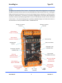
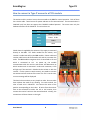
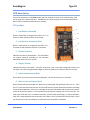
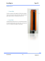
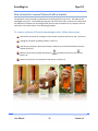
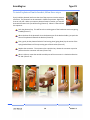
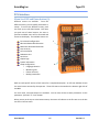
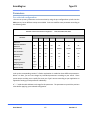
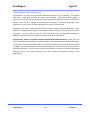
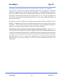
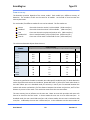
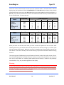
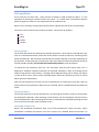
 ScanMeg Inc. Type P3 USER MANUAL Version 1.5 October 2014 ScanMeg Inc. Type P3 User Manual 2 Version 1.5 ScanMeg Inc. Type P3 Introduction .................................................................................................................................. 5 P sensor Head ................................................................................................................................ 6 PCU ............................................................................................................................................... 7 How to connect a Type P sensor to a PCU module .......................................................................... 8 LED description .............................................................................................................................. 9 PCU module ............................................................................................................................................................................... 9 Emitter head ............................................................................................................................................................................ 10 Receiver head ........................................................................................................................................................................... 11 Emitter, receiver or PCU swap: Useful information .................................................................... 12 Emitter ..................................................................................................................................................................................... 12 Receiver ................................................................................................................................................................................... 12 PCU module ............................................................................................................................................................................. 12 How to install or remove Photocell with a bracket ....................................................................... 13 To remove a photocell from its mounting bracket, follow these steps: ................................................................................... 13 To install a photocell on its bracket, follow these steps: .......................................................................................................... 14 PCU interface ............................................................................................................................... 15 Menu Scroll UP and Down button (A) ...................................................................................................................................... 15 Previous and next parameter button (B) .................................................................................................................................. 16 Enter parameter button (C) ...................................................................................................................................................... 16 Alphanumeric display (D) ......................................................................................................................................................... 16 Parameters .................................................................................................................................. 17 Pre‐selected configuration ....................................................................................................................................................... 17 Minimum detectable dimension .............................................................................................................................................. 18 Maximum detectable dimension (need software version 1.4 or higher) ................................................................................. 19 Scan accuracy ........................................................................................................................................................................... 20 Cell cancellation ....................................................................................................................................................................... 22 Debounce time ......................................................................................................................................................................... 24 Latch time ................................................................................................................................................................................ 24 Output logic ............................................................................................................................................................................. 24 System information .................................................................................................................................................................. 25 Setup: Language selection ....................................................................................................................................................... 26 Setup: Measuring unit ............................................................................................................................................................. 26 Setup: Emitter intensity ........................................................................................................................................................... 26 Setup: Backup parameters ....................................................................................................................................................... 26 User Manual 3 Version 1.5 ScanMeg Inc. Type P3 User Manual 4 Version 1.5 ScanMeg Inc. Type P3 Introduction
The P sensor is an area photocell made up of an emitter and receiver. The sensor detects objects as small as 0.1 inch (2.5mm). The emitter and the receiver can be mounted up to 100 feet (30m) apart. The P sensor has two outputs: one standard PNP contact and a one standard NPN contact. The unit is a closed enclosure with a military, quick‐disconnect, connector. A small controller is supplied with the photocell. All parameters can be programmed with this Photocell Controller Unit. The emitter and the receiver are connected directly to the PCU. An eight character alphanumeric digital display shows each parameter and available configuration. The PCU is configured using 5 keys located below the display. Status of each cell of the receiver (blocked, cancelled; not blocked) can be seen through its window or on the PCU’s remote display. Connection of the emitter and receiver is simple using four colored wires and each color is identified directly on the terminals connectors located on the PCU. Two terminals are present, one for the receiver and the other for the emitter. These connectors are not dedicated as they can either, accept, emitter or receiver. The only restriction is to have an emitter unit and a receiver unit connected to the PCU. Mechanical, electrical or interconnection drawings are available in AutoCAD format and if required please contact our technical support team. User Manual 5 Version 1.5 ScanMeg Inc. Type P3 P sensor Head
The P photocell is a sealed enclosure. The head is rated NEMA 4 or IP66 . Each head has a quick‐
disconnect connector with four contacts. Two series of LEDs indicate the state of each cell present in the sensor. The component of the emitter and the receiver are as follows: LED Power LED Presence
Bracket LED Power LED State for each cell LED Synchro Quick Disconnect connector Bracket Receiver Quick Disconnect connector Emitter
User Manual 6 Version 1.5 ScanMeg Inc. Type P3 PCU
The PCU is the controller of the P sensor. All parameters setups and configurations are made with the PCU. The emitter and the receiver are connected directly to the terminal of this unit. Viewing the display and using the push buttons, one can view and change setups or parameters. All of these values are kept in a flash memory. At power up, all previous configurations are still there and the photocell continues to work as previously programmed. A series of LED indicates the state of each cell located in the receiver. This remote viewing state is useful for troubleshooting the unit when the receiver is not mounted in an easily accessible location. The PCU looks like: Emitter or receiver Terminal Emitter or receiver Terminal LED indicates Emitter connected LED indicates Receiver connected Menu scroll up Menu scroll down Alphanumeric Display Parameter: next available value Parameter: previous available value Enter button to validate new entry LED array indicates state of each receiver cell LED array indicator shows actual selected menu LED indicates an object is detected LED Power indicator Internal Supply 15 Vdc PNP Output User Manual Power input (24volts) 7 NPN Output LED indicator External Supply 24 Vdc Version 1.5 ScanMeg Inc. Type P3 How to connect a Type P sensor to a PCU module
The emitter and the receiver have to be connected to the PCU for normal operation. Each of them has a 4‐wire cable. Two wires are for power and two are for communication. The communication is CAN‐BUS level, but does not support the CAN‐BUS standard protocol. The sensor uses only the hardware features of the CAN‐BUS. The wire colors are: Color Description Red Power +15Vdc Black Power 0 Vdc White CANH Green CANL 24Vdc Power is supplied by the customer. This supply is connected directly to the PCU. The 15Vdc needed for the emitter, and receiver is made internally by the PCU module. Emitter cable and receiver cable have to be connected at J12 and J14, no matter the order. The PCU module recognizes which is connected at J12 and which is connected to J14. At power up, the module communicates with the receiver and emitter and determines at which location each is connected. Under each connector, a LED will light up if the terminal is linked with the emitter or with the receiver. For the system to work correctly, one needs to connect one emitter and one receiver of the same size. If it is not the case, an error message will be displayed. The electrical connections are very simple to make. One can make them without the need of any drawing. On each terminal, the color of each wire is identified. Just connect the wires at the position corresponding to their color. All wires from the emitter have to be connected to either the J12 or J14 location; then connect the receiver’s wires on the unused terminal. Visually, the connections will be as shown on the right . User Manual 8 Version 1.5 ScanMeg Inc. Type P3 LED description
Some LEDs are present on the PCU module and also inside the emitter or the receiver head. Each one or group has a specific function. The PCU has red, yellow and green LED to help identification. Both receiver and emitter heads use only red LEDs. PCUmodule
1 1. Led Emitter Connected
2 When a valid emitter is recognized, this LED is “on”, no matter to which side the emitter is connected. 6 2. Led Receiver Connected (Red)
3 When a valid receiver is recognized, this LED is “on”, no matter to which side the receiver is connected. 5 3. Presence (Green)
Indicates the state of the detection. The LED follows the output detection according to the minimum detectable dimension in the system. 4 4. Supply (Yellow)
Indicates the state of the supply. Two LEDs are present. One is the input voltage (24 Volts dc) and the other is the internally generated voltage (15 Volts dc) used by the emitter and by the receiver. 5. Actual selected menu (Red)
Shows which one of the menus is actually displayed. This LED is used only as a reminder. 6. State of each cell sensor (Red)
Shows the state of each individual cell. When a cell is obstructed, the equivalent LED is set “on”. Each LED “on” can have two intensity levels. An LED at half intensity shows an obstructed cell but according to the minimum diameter, there are not enough consecutive LEDs obstructed to activate the output. A total of 32 LEDs is present. In low resolution only 16 LEDs are working, one at every two LED. The other stays off all the time. In medium resolution, all the 32 LEDs are working. In coarse resolution, each LED is associated with two consecutive cells. When a cell is cancelled the LED will flash 2 times per second until a reset cancellation is performed or the cancellation is disabled. User Manual 9 Version 1.5 ScanMeg Inc. Type P3 Emitterhead
7 7. Power (Red)
8 The LED is located at the opposite end from the connector. The one at the top is the supply LED status. When the PCU has power and the emitter is connected, this LED is “on”. 8. Sync (Red)
The LED below the power LED is “on” to indicate the presence of a synchronization pulse at the emitter level. If the sync LED is not “on”, detection of an object is not possible. User Manual 10 Version 1.5 ScanMeg Inc. Type P3 Receiverhead
9. Power
The LED is located at the opposite end of the connector. The one at the top is the supply LED status. When the PCU is under power and the receiver is connected, this LED is “on”. 9 10 10. Presence
Below the Power LED, two LEDs are present. Each of them is offset each from the center line of the photocell. When the photocell detects a valid object according to the minimum detectable dimension, both LEDs are “on”. These LEDs always follow the state of the green LED (presence) located on the PCU module. 11 11. Each cell state
Below the power presence LED, two rows of LEDs are located on each side of the center line of the widow. When a cell is obstructed, the equivalent LED located on each side of this cell is set “on”. A total of 64 LEDs are present. According to the scan precision, more or less LEDs are set “on”. In coarse resolution, 16 are working, in medium resolution 32 and, in high resolution, all 64 LEDs are working. Unlike the PCU’s LEDs, the half‐intensity level does not exist in the receiver to indicate that the minimum detectable object has not been reached. If this were the case, some LEDs are “on”, but the two presence LEDs are not “on” indicating that the photocell detects something that is less than the minimum detectable diameter. When a cell is cancelled, the corresponding LED will flash 2 times per second until a reset cancellation is performed, or the cancellation is disabled. User Manual 11 Version 1.5 ScanMeg Inc. Emitter, receiver or PCU swap:
Type P3 Useful information
At any time, one can replace the emitter, the receiver or the PCU. Some of these replacements are transparent in the operation of the photocell, some are not. The parameters are located in the PCU module. After a power up, the parameters are read from the flash memory of the PCU for normal operation. The receiver contains a memory backup of the PCU’s parameters. The parameters can be retrieved if necessary. The emitter has no memory to store parameters. In the following paragraph, each component is described. Emitter
The emitter can be replaced without any influence on the photocell operation. When the PCU detects the receiver, all the actual parameters needed to operate correctly are sent to the emitter. As soon as the emitter has received the parameters, the photocell starts to work. Receiver
An emitter can be replaced without any influence on the photocell operation. The receiver however is the backup memory of the PCU module. When you modify it, the actual backup is no longer available. If you replace the receiver and the PCU module at the same time, you cannot operate the photocell as it was working before the change. Try to avoid replacing the receiver and the PCU during the same power down operation. To update the backup memory of the PCU module inside the new receiver, you need to follow one of these steps: Modify one parameter in the PCU module. Every time a parameter is changed, the complete memory is sent to the receiver memory for backup purpose. Any change of a parameter makes a full update in the receiver memory. Execute the “save parameter” command from the PCU command menu. This command will take the data in the PCU’s parameter memory and send it directly to the receiver’s memory to update the new receiver PCUmodule
When the PCU module is replaced, the parameter’s memory is gone with the old PCU module. It means that the photocell will not work as it was working before the PCU swap. You can, however, retrieve all of the old parameters from the receiver by doing the following: Execute the “retrieve” command from the new PCU module. This command must be executed before any parameters are changed. If a parameter is changed first, you will lose all the backup parameter available in the receiver head. User Manual 12 Version 1.5 ScanMeg Inc. Type P3 How to install or remove Photocell with a bracket
The photocell can be removed or installed on its mounting bracket at any time. The cable can be unplugged at any time. In the following paragraph, we will connect and un‐connect the cables when the photocell is fixed onto its mounting bracket, but this step can be done in any sequence and not necessarily in the order shown in the following procedure . Toremoveaphotocellfromitsmountingbracket,followthesesteps:
Remove the connector by rotating the shell counter clockwise direction by 120o ( Picture 1). Unplug the connector by pulling it down ( Picture 2). Grab only the photocell, without the bracket, and push up to release the bottom from the bracket (Picture 3). Maintain the pressure and pull the bottom part of the photocell away from the bracket. (Picture 4). Release the pressure on the photocell and remove it (Picture 5). Picture 1 Picture 3 Picture 2 Picture 5 Picture 4 User Manual 13 Version 1.5 ScanMeg Inc. Type P3 Toinstallaphotocellonitsbracket,followthesesteps:
Firmly hold the photocell and insert the slot of the top cover into the top part of bracket. The photocell can be mounted in 3 different positions: Right side, Front or Left side. When you mount a photocell onto its bracket, you need to know which fixation hole you will be using (Picture 6). When it is done follow this sequence: Picture 6
Push the photocell up. This will force the retaining part of the bracket to come out (spring loaded) (Picture 7). When the base of the photocell clears the bottom part of the bracket holder, just push the base of the photocell towards the bracket (Picture 8). Then, gently let the photocell take his final resting place (going down) by the action of the spring loaded feature of the top moving part of the bracket (Picture 9). Replace the connector. The connector has a position key. Rotate the connector up to the position that the connector will enter (Picture 10). When it is done, rotate the outside movable part of the connecter in a clockwise direction for 120 o (Picture 11). Picture 3 Picture 8 Picture 9 Picture 10 Picture 11 User Manual 14 Version 1.5 ScanMeg Inc. Type P3 PCU interface
MenuScrollUPandDownbutton(A)
Different menus are available. From the different menus, you can modify parameters or setups. To access the different menus, push the scroll up or scroll down button. Each time you push one of these buttons; the next or previous available menu will be accessed and shown on the display. The available menus are: D C Pre‐selected configuration Minimum detectable dimension Maximum detectable dimension Scan accuracy Cell cancellation Debounce time Latch time Output logic System information Setup configuration: o Language selection o Measuring unit o Emitter intensity o Backup parameters A B Refer to each specific section of each menu for a complete description. An LED row indicator shows the actual menu accessed by the operator. These LED rows are located on the bottom right side of the PCU. For each menu, some parameters are available. You can have access to these parameters via the parameter “previous” or “next” button. When you are at the top or at the bottom menu, the menu will rollover to the first one or to the last one like an infinite menu. User Manual 15 Version 1.5 ScanMeg Inc. Type P3 Previousandnextparameterbutton(B)
Each time you access a new menu, a scrolling message identifying the actual menu being accessed is shown on the display. When this message is finished the actual parameter is displayed. To access the available parameters on this menu, push the next or previous value button. Each time, a new available parameter value is displayed and flashing. Only the active parameter in the accessed menu is displayed in static view (non‐flashing). All the other non‐active parameters will be flashing to indicate that they are not active. To change a value to a new one, maintain the Enter button for one second to validate the new active parameter. At this time, this parameter will stop flashing to indicate it is now the new active parameter for this menu. At any time you can push the “next” or “previous” value button including at the beginning when the scrolling message is displayed. When this is done, the next parameter will be displayed (in flashing mode). The rest of the scrolling message is halted by this sequence. For some menus, the software asks for a validation or to quit. At this time the previous button will become the OK answer and the next button the quit answer. Enterparameterbutton(C)
The Enter button validates a new parameter entry. When the preferred parameter is shown on the display, the new parameter can be validated by holding down the button for 1 second. Maintaining a button for a certain time avoids an accidental contact on this button. When you maintain a button for 1 second, it is because you really want to do this action. Alphanumericdisplay(D)
All the parameters and messages can be seen via the display. According to the type of messages, some will scroll and others will be fixed. For all text appearing on the display, units are in the language and measuring unit selected User Manual 16 Version 1.5 ScanMeg Inc. Type P3 Parameters
Pre‐selectedconfiguration
One can set up many parameters at the same time by using the pre‐configured set up built into the PCU memory. Seven different setups are available. Each one modifies some parameter according to the following table: Parameter value for Pre-selected configuration
P150, P225, P300, P450, P600
Pre‐selected configuration Parameter
Default Fast Average Accurate Standard Severe Extreme Minimum detectable
dimension
Off Off Off Off 50 mm / 2.4 in. 80 mm / 3.2 in. 120 mm / 4.7 in. Maximum detectable
dimension
Off Off Off Off Off Off Off Standard Coarse Standard Fine Standard Standard Standard Cell cancellation
‐‐‐ ‐‐‐ ‐‐‐ ‐‐‐ ‐‐‐ ‐‐‐ ‐‐‐ Debounce time
2ms Off Off Off 5ms 10ms 15ms Latch time
Off Off Off Off Off Off Off Light ‐‐‐ ‐‐‐ ‐‐‐ ‐‐‐ ‐‐‐ ‐‐‐ Language selection
English ‐‐‐ ‐‐‐ ‐‐‐ ‐‐‐ ‐‐‐ ‐‐‐ Measuring unit
Imperial ‐‐‐ ‐‐‐ ‐‐‐ ‐‐‐ ‐‐‐ ‐‐‐ High High High Low High High High Scan accuracy
Output logic
Emitter intensity
Look up the corresponding section if a further explanation is needed on these different parameters. When it is done, you can now change any individual parameters according to your needs. These preset setups can help you to rapidly fine tune your Type P sensors according to your application as opposed to setting up each parameter individually. A ”‐‐‐“ inside the table indicates no change for this parameter. The parameter stays with the previous value before applying a pre‐selected configuration. User Manual 17 Version 1.5 ScanMeg Inc. Type P3 Minimumdetectabledimension
This parameter is used to fix the minimum detectable dimension by the Photocell. If the object dimension is smaller than this value, the output is not activated. If the detected objet is bigger or equal to this value, the PNP or the NPN output will be activated. When the output is activated, the Presence LED is set “on”. The logic of the output can be inversed. This is done via the logic output parameters. In such a case, the logic described in this section is also inversed. According to the sensor model and the selected scanning resolution, different dimensions can be detected. The PCU will only display the available detectable value for the actual setup and Type P connected. Each time that you push the next value button, the next detectable dimension is displayed. The same principle is applied if you push the previous value button. This parameter works in conjuncture with the maximum detectable dimension. When you try to enter a new value, if the minimum is not equal or lower to the actual maximum detectable dimension, one can never validate this parameter value. No matter the number of time you push the Enter button to validate; this value will continue to flash and never becomes the new value set for the minimum detectable dimension. One can choose a new valid dimension or modify the maximum detectable dimension with a valid value according to the desire minimum detectable dimension to be programmed. User Manual 18 Version 1.5 ScanMeg Inc. Type P3 Maximumdetectabledimension(needsoftwareversion1.4orhigher)
This parameter is used to fix the maximum detectable dimension by the Photocell. If the object dimension is bigger than this value, the output is not activated. If the detected objet is smaller or equal to this value and respect the minimum detectable dimension, the PNP or the NPN output will be activated. When the output is activated, the Presence LED is set “on”. The logic of the output can be inversed. This is done via the logic output parameters. In such a case, the logic described in this section is also inversed. According to the sensor model and the selected scanning resolution, different dimensions can be detected. The PCU will only display the available detectable value for the actual setup and Type P connected. Each time that you push the next value button, the next detectable dimension is displayed. The same principle is applied if you push the previous value button. This parameter works in conjuncture with the minimum detectable dimension. When you try to enter a new value, if the maximum is not equal or bigger to the actual minimum detectable dimension, one can never validate this parameter value. No matter the number of time you push the Enter button to validate; this value will continue to flash and never becomes the new value set for the maximum detectable dimension. One can choose a new valid dimension or modify the minimum detectable dimension with a valid value according to the desire maximum detectable dimension to be programmed. User Manual 19 Version 1.5 ScanMeg Inc. Type P3 Scanaccuracy
The detection precision depends of the sensor model. Each model has a different accuracy of detection. The numbers of cells are the same for all models. As the field of view increases the accuracy decreases. For each model, five different modes of scan can be selected. The five modes are: Coarse Standard Fine Standard HS Fine HS : Scan with the entire receiver’s cells available. (1500 scans/sec.) : Scan with the entire emitter’s LEDs available. (800 scans/sec.) : Cross scan the entire emitter and receiver cells. (400 scans/sec.) : Scan in standard mode ½ of the field of view. (1500 scans/sec.) : Cross scan in fine mode ¼ of the field of view. (1500 scans/sec.) The minimum detectable object dimensions are: P150
P225
P300
P450
P600
Fine & Fine HD 0.4 0.6 0.8 1.2 1.6 10 15 20 30 40 0.2 0.3 0.4 0.6 0.8 5 7.5 10 15 20 0.1 0.15 0.2 0.3 0.4 2.5 3.75 5 7.5 10 Inch P150
P225
P300
P450
P600
Coarse Scan Accuracy Standard & Standard HD mm Model The accuracy specified in the table is reachable, but under specific conditions only. To obtain detection under all possible environment and condition, please add 0.025 in. (0.5mm) for each value shown in the table. When you are in Standard mode, the accuracy is true if you are centered between the emitter and receiver and within 1/3 of the distance between the emitter and receiver; and ¼ of the distance is you are in Fine mode. This restriction comes from the cross scan effect. The scan accuracy has an influence on the scan rate. More we scan with precision and more cells have to be check for the final result. In Coarse mode the scan rate is set to 1500 scans/sec.. In Standard mode, the scan rate is 800 scans/sec. and in Coarse mode, the scan rate is reduced to 400 scans/sec.. In HS mode, the scan rate is 1500 scans/sec. In that mode we scan the same number of User Manual 20 Version 1.5 ScanMeg Inc. Type P3 cells of the coarse mode but with the accuracy of the equivalent mode. The field of view is reduced but the scan rate is optimum. When the Standard HS or the Fine HS mode are chosen, only a section of the field of view is scan to run with High Speed scan rate at the Standard or the Fine resolution. In HS mode, only half of the field of view is scan for the Standard HS mode and only ¼ of the field of view for the Fine HS mode. The scan rates are: Model Coarse
Standard
Fine
Standard HS
Fine HS
Scans Rate scans/second P150 1500 800 400 1500 1500 6 6 6 3 1.5 Field of view (in.) P225 P300 P450 9 9 9 4.5 2.25 12 12 12 6 3 18 18 18 9 4.5 P600 24 24 24 12 6 Model Coarse
Standard
Fine
Standard HS
Fine HS
Scans Rate scans/second P150 Field of view (mm) P225 P300 P450 1500 800 400 1500 1500 150 150 150 75 37.5 225 225 225 112.5 56.25 300 300 300 150 75 450 450 450 225 112.5 P600 600 600 600 300 150 When you select one of these scan mode, you have to select the position of the scan zone. After validating the mode, you need to select also the position of the zone by moving it up or down (next value or previous value button). When the scan zone is located at the correct position, just push the Enter button. If the zone is already at the correct location, just push the Enter button without moving the zone. The scanning zone will be displayed on the LED status of each cell. When this mode is chosen, all non‐
scan LEDs are displayed like cancelled LED (note: but they are not really cancelled, as one can see as soon as one comes back to a scanning mode without the HS feature). However real previously cancelled LEDs, if any, stay canceled regardless of the display. Warning IF YOU TRY TO SCAN WITH ACCURACY IN FINE MODE AND THE DISTANCE OF THE EMITTER OR RECEIVED IS LESS THAN 6 FEET (2M), YOU NEED TO PUT THE INTENSITY OF THE EMITTER TO LOW. IF NOT, THE INTENSITY IS TOO HIGH MAKING A BLUR EFFECT. THIS EFFECT RESULTS IN A LOST IN ACCURACY. User Manual 21 Version 1.5 ScanMeg Inc. Type P3 Cellcancellation
At any time you can cancel cells. These cells will no longer be used to detect an object. It is the equivalent of removing the actual cell from the sensor. It is useful when a mechanical structure passes through the sensor or in the unexpected case of a defective cell. When a cell is cancelled, the equivalent LED will flash to indicate the state of this cell (cancelled). This menu is like a function that you want to execute. Four actions can be done: Set Reset Enable Disable TheSetfunction
This function will look for non‐working cells and will cancel them. All the cells are scanned and, if any cells are in the obstructed state, those cells will be placed in memory inside a list containing all the actual cancelled cells. None of these cancelled cells are used for detection in the normal operation of the photocell. At the same time, no matter the state of this function before the execution of the set function (enable / disable), this function will automatically Enable the cell cancellation. To execute the Set command, select the “Set” parameter with the enter button when “Set” is displayed. A validation command execution will be asked. Validation is done by choosing the OK answer (using previous value button), a message will be displayed asking you to remove any objects in front of the P sensor! When all the unwanted objects have been removed, just click on the OK button (previous value button). Each time one executes this function, the list of cancelled cells is cleared and a new scan is done to make a new list of cancelled cells. When the scan is finished, the list is updated with all cancelled cells found. TheResetfunction
This function clears the list of the cancelled cells. By executing this function, all cells are now used by the photocell for detection. After executing a reset function, the cell cancellation function will then be in the disable state. When executing this function, a confirmation is asked before making the reset to be certain that you really want to execute a reset. TheEnable/Disablestate
When a cell cancellation command is done, a list of the cancelled cells is kept in memory. When Cancellation is enabled, cells present in the list in memory are cancelled. When this function is in User Manual 22 Version 1.5 ScanMeg Inc. Type P3 Disable state, the list is still there, but no cells are cancelled. This permits to test all the cell of the photocell without losing the state of the cancelled cell. At any time you can enable them. The Enable / Disable state is the equivalent of the Set or Reset function but without any update or reset of the cancelled list. User Manual 23 Version 1.5 ScanMeg Inc. Type P3 Debouncetime
This is the minimum amount of time that an object is allowed to stay in the field of view of the photocell in order to be detected. Once a change of state has been detected by the photocell, a counter is started. If the photocell goes back to its original state before the counter has reached your selected time period there will be no change in the state of the output signal. The feature is the same for obstructed state to non‐obstructed state as well as for the non‐obstructed state to obstructed state. This allows the user to adjust the ScanType P to ignore transient objects such as flying debris, bark, chips or sawdust. To set up a new debounce time, choose the pre‐selected value available from the list. When the right one is displayed, just maintain the Enter button for one second to fix the chosen debounce time in memory. Latchtime
Once the photocell has detected an object the duration of the output signal (regardless of the object still being detected) can be adjusted. This allows you to determine how long the output will stay “ON” once it has detected a presence. This value is the minimum time only. If an object remains inside of the field of view, the output will stay activated as long as the object blocks LEDs. The output pulse value is in milliseconds. This parameter can be changed at any time. At the next photocell scan, the output signal will be set according to the new switch position. This adjustment is useful when you connect the photocell with a device or a controller that is slower than the scan rate of the photocell. This feature allows the controller to have time to see the output coming from the photocell. Outputlogic
Once a presence is detected by the photocell the output changes. You can choose either a Light logic operation or a Dark logic operation. The Light logic will close the contact when a presence is detected and release the contact when the object leaves the field of view. The Dark logic is the inverse of the Light logic. User Manual 24 Version 1.5 ScanMeg Inc. Type P3 Systeminformation
When this menu is the active one, the display shows all the actual setup parameters. A small message is scrolled to indicate which one is been displayed. The value follows the message. After a few seconds, the time to read it, the next parameter is displayed. When it has gone through all the parameters, the PCU repeats the display sequence from the first parameter. After 3 times, the display is powered off like a screen saver. If any button is touched, the display will come back. All the features of the photocell are still working during the screen saver feature. Only the display is disabled. The parameters appeared on the display in the following order: Software version of the PCU module, Emitter head and Receiver head Pre‐selected configuration Minimum detectable dimension Scan accuracy Cell cancellation Debounce time Latch time Output logic Language selection Measuring unit Emitter intensity The row of L.E.Ds on the right side of the PCU normally shows the actual selected menu. For the system information, the corresponding L.E.D. is “on”, but every time a setup parameter is displayed, the equivalent L.E.D. is also “on” but with only half intensity. This feature is useful to know which parameter is displayed at the present time. The intensity is also useful to distinguish the actual menu (normal intensity) compared to the scrolling parameter display (half intensity). User Manual 25 Version 1.5 ScanMeg Inc. Type P3 Setup:Languageselection
Five languages are available for the PCU interface. The languages are: English, French, German, Italian and Spanish. Just select the language. When the language is validated, the entire menus are displayed with this new set‐up. Setup:Measuringunit
The metric system and the imperial system are the two measuring systems available. When one of these is selected, all the corresponding values follow the chosen measuring system until a new selection is made. Setup:Emitterintensity
Eleven intensities are available. At minimum intensity, the maximum operating distance is 7.5 feet (2 meter). At the maximum intensity, the operating distance is up to 100 feet (30 meter). The minimum intensity is an absolute necessity when the emitter and the receiver are mounted within a very short distance of one another and you are trying to detect an object with high precision (mode). The High intensity is too intense and some receiver cells will make a reading error around both edges of the object, losing accuracy. Setup:Backupparameters
All parameters are located within the PCU module. When an emitter or/and a receiver is replaced, the photocell will continue to operate as before. If one replaces the PCU module, the situation is not the same. You can retrieve all the original parameter setups from the receiver head (backup of the PCU parameters). To do so, you need to execute the “retrieve” parameter function before making any modification to any parameter. At any time, you can force all the parameters to be backed‐up inside the receiver head. Normally, a backup of each parameter is done when any individual parameter is modified but you can force all parameters to be saved by using this command execution. User Manual 26 Version 1.5