1
4DA35B/9102B
y 4DA36B/9106B
ENSAMBLADO
Hélice
Girador
Tuerca de
Plástico
Parrilla
Anterior
Figura 1
OSCILACIÓN VARIABLE: Jale la perilla de oscilación ubicada
en la parte posterior del motor hacia arriba. Gire el cabezal del
ventilador hacia la izquierda, derecha o hacia delante. Empuje la
perilla de oscilación hacia abajo y el ventilador oscilará describiendo el
ángulo fijado.
ÁNGULO VERTICAL: Para ajustar el ángulo vertical, incline el cabezal
del ventilador hacia arriba o abajo, según prefiera.
VELOCIDAD: La velocidad está controlada por una perilla rotatoria:
(0) Apagado, (3) Alta, (2) Media, (1) Baja.
CABLE ELÉCTRICO: Enchufe el cable eléctrico en un tomacorriente
de pared (CA 120 Voltios, 60 Hz).
MANTENIMIENTO
ADVERTENCIA: SIEMPRE DESENCHUFE EL CABLE ANTES
DE MOVER O DAR SERVICIO AL VENTILADOR.
ADVERTENCIA: ¡NO SUMERJA EL VENTILADOR EN AGUA!
LIMPIEZA: Utilice un paño suave humedecido con una solución
jabonosa liviana, tal como un detergente líquido para lavar platos.
Seque TODAS LAS PARTES POR COMPLETO antes de rearmar.
Después de dar mantenimiento o servicio, REARME POR COMPLETO
la unidad en la forma descrita en este manual de instrucciones,
antes de volver a conectarla a la fuente de poder.
PRECAUCIÓN: No utilice gasolina, bencina, acetona,
limpiadores abrasivos, etc. puesto que dañarán el Ventilador.
NUNCA use ALCOHOL O SOLVENTES.
LUBRICACIÓN: Los cojinetes de precisión vienen sellados de por
vida en la fábrica y no precisarán ninguna lubricación adicional.
ALMACENAMIENTO: Guarde el Ventilador con estas instrucciones
en un lugar fresco y seco.
REPARACIONES: Cualesquiera otras reparaciones, con la
excepción del mantenimiento general a cargo del usuario, deben
ser realizadas por un representante de servicio autorizado.
Clavija
Parrilla
Posterior
Motor
Figura 3
Figura 2
Ranura
Espiga
LISTA DE REPUESTOS
REF
1
2
3
4
5
6
7
8
9
10
11
12
13
14
15
16
17
18
19
16
14
12
13
1
5
4
17
7
6
3
DESCRIPCIÓN
4DA35B/9102B
4DA36B/9106B CANT.
Motor
Interruptor
Plastico Protector
Resorte de elevaci
Placa de trinquete
Eje de elevación
Tuerca hexagonal de 5/16-24
Base
Perilla del Interruptor
Placa Inferior
Cordón eléctrico con clavija
Rejilla frontal
Tapa
Aspa
Tuerca de plastica
Rejilla plastica trasera
Ornamento de la rejilla
Pata de caucho
Tornillo #8 X 9/16 PPH
02035053
02055087
7091854
02035052
02055087
7091854
02090586
02010162B
02090521
02090033
2010541
2010131
2010315
02050009FPB
020962141
2010093
2011013
2010359P
2011200M
02010381A
2010415
2090039
02010162B
02090521
02090033
2010540P
2010131
2010313
02050009FPB
02096217
2010093
2010008
2010359P
2011212
02010381A
2010415
2090039
1
1
1
1
1
1
1
1
1
1
1
1
1
1
1
1
1
2
1
9
2
8
11
10
19
18
Rev. F 10/09
4
12" (30,5 cm) MODEL 4DA35B/9102B
16" (40,6 cm) MODEL 4DA36B/9106B
READ AND SAVE THESE INSTRUCTIONS
READ CAREFULLY BEFORE ATTEMPTING TO ASSEMBLE, INSTALL, OPERATE OR MAINTAIN THE PRODUCT DESCRIBED. PROTECT YOURSELF AND OTHERS BY OBSERVING ALL SAFETY INFORMATION. FAILURE TO COMPLY
WITH INSTRUCTIONS COULD RESULT IN PERSONAL INJURY AND/OR PROPERTY DAMAGE!
DESCRIPTION
RETAIN INSTRUCTIONS FOR FUTURE REFERENCE.
WARNING: USE OF A THREE-PRONG TO TWO-PRONG
The Air King ® 12" (30,5 cm) and 16" (40,6 cm) Oscillating Fans feature
whisper quiet operation with a 3 paddle blade. Fan is powered by
a pre-lubricated permanent split capacitor motor with a 6 ft. (1.8 m)
18/3 cord set. Fan grills meet OSHA requirements. ETL listed.
SPECIFICATIONS
Motor......................................... 120V, 60Hz (12")(30,5 cm)
120V, 60Hz (16")(40,6 cm)
Blade Size................................. 12" (30,5 cm) Model(4DA35B/9102B)
16" (40,6 cm) Model(4DA36B/9106B)
Speeds...................................... 3 Speeds
Control...................................... Rotary Knob
Air Flow Distribution................. 90°
MODEL
4DA35B/9102B
SPEED HIGH
MED LOW
CFM
930
780
620
M3/s
0.43
0.37
0.29
RPM
1450
1300
1090
Amps
0.40
0.30
0.27
Watts
39
35
32
dB (A)
45
41
36
4DA36B/9106B
HIGH
MED LOW
1710
1500 1330
0.80
0.71
0.63
1545
1394 1244
0.71
0.54
0.48
77
65
57
53
49
44
GENERAL SAFETY INFORMATION
NO. DE PARTE PARA EL MODELO
Figura 3
15
OSCILLATING FANS
FUNCIONAMIENTO
1. Incline el cabezal del ventilador hacia atrás. Coloque la Parrilla
Plástica Posterior en el Motor. (Figura 1)
2. Alinee el corte triangular en “∆” en la Parrilla Plástica Posterior
con el poste triangular en la parte superior de la cubierta frontal
del Motor. Encaje totalmente la Parrilla Plástica Posterior y
fíjela con la Tuerca de Plástico, haciéndola girar en el Sentido
de las Manecillas del Reloj. (Figura 2)
3. Deslice la Hélice sobre el Eje del Motor. (Alinee la Ranura en el
bloque de la hélice con la Clavija del eje del motor.) (Figura 3)
4. Para fijar la Hélice, atornille el Girador en el Eje en el
Sentido Contrario a las Manecillas del Reloj hasta que
se encuentre fija en el cubo de la hélice.
5. Con el cabezal del ventilador en posición recta, alinee el
Ornamento de la Parrilla Anterior para que quede en posición
horizontal. Inserte la parte inferior de la Parrilla Anterior dentro de
la Parrilla Plástica Posterior. La Lengüeta en la parte inferior de
la Parrilla Plástica Posterior debería encajar entre los rayos de la
Parrilla Anterior. Encaje la Parrilla Anterior dentro de la Parrilla
Plástica Posterior comenzando desde arriba y progresando en
forma descendiente por ambos lados.
Parrilla
Posterior
OPERATING INSTRUCTIONS & PARTS MANUAL
2084067
When using electrical appliances, basic precautions should always be followed to reduce
the risk of fire, electric shock and injury to person,
including the following:
1. Read all instructions before using Fan. 2. Make certain that the power source conforms to the electrical
requirements of the Fan.
3. Use this Fan only as described in this manual. Any other use
not recommended by the manufacturer may cause fire, electrical
shock, or injury to persons.
4. Unplug power cord before installing, servicing, or moving the Fan.
WARNING: DO NOT DEPEND UPON THE ON-OFF
SWITCH AS THE SOLE MEANS OF DISCONNECTING
POWER WHEN INSTALLING OR SERVICING THE FAN.
ALWAYS UNPLUG THE POWER CORD.
5. This Fan must NOT be used in potentially dangerous
locations such as flammable, explosive, chemical-laden
or wet atmospheres.
6. DO NOT use Fan in or near a window. Rain may create an
electrical hazard.
7. The power cord is equipped with a three-prong grounded plug
that must be inserted into a matching receptacle. Under no
circumstances should the grounding prong be cut off the plug.
Where a two-prong wall receptacle is encountered, it must
be replaced with a properly grounded three-prong receptacle
installed in accordance with the National Electrical Code (NEC)
and all applicable local codes and ordinances. This work must
be done only by a qualified electrician, using
copper wire only.
Rev. F 10/09
1
ADAPTER IS NOT RECOMMENDED. IMPROPER CONNECTION MAY CREATE THE RISK OF ELECTROCUTION. USE
OF SUCH ADAPTERS IS NOT PERMITTED IN CANADA.
WARNING: This plug is a safety feature. To
reduce the risk of fire, electric shock and
personal injury, do not remove, replace, repair
or tamper with the originally supplied plug. If
the Fan does not function properly, it may be
due to the safety device incorporated in this
plug.
8. Where possible, avoid the use of extension cords. If they must
be used, minimize the risk of overheating by ensuring that they
are UL listed. Never use a single extension cord to operate more
than one Fan.
9. Do not operate any Fan with a damaged cord or plug or after
the Fan malfunctions, has been dropped or damaged in any
manner.
10.Do not insert or allow fingers or foreign objects to enter any
ventilation or exhaust opening as it may cause an electric shock
or fire, or damage the Fan. Do not block or tamper with the
Fan in any manner while it is in operation.
11.Always place the Fan on a stable, flat, level surface when
operating, to avoid the chance of the Fan overturning. Locate
the Power Cord so the Fan or other objects are not resting on it.
Do not run Power Cord under carpeting. Do not cover Power
Cord with throw rugs, runners, or the like. Arrange Power Cord
away from room traffic and where it will not be tripped over.
12.This Fan is not intended for use in wet or damp locations.
Never locate a Fan where it may fall into a bathtub or other water
container.
13.Do not use Fan outdoors.
14.This Fan is not suitable for use in agricultural facilities including
areas where livestock, poultry or other animals are confined.
Please refer to National Electric Code (NEC) Article 547-7
(2008), or applicable state or local codes or standards relating
to electrical requirements for Agricultural Buildings. THIS FAN
DOES NOT MEET THE REQUIREMENTS OF NEC ARTICLE
547-7 (2008).
15.This Fan is not suitable for use in hazardous locations. Please
refer to National Electric Code (NEC) Article 500 or applicable state
or local codes or standards relating to electrical requirements
for Hazardous locations. THIS FAN DOES NOT MEET THE
REQUIREMENTS OF NEC ARTICLE 500 (2008).
WARNING: REDUCE THE RISK OF FIRE OR ELECTRIC
SHOCK – DO NOT USE THIS FAN WITH ANY SOLID STATE
SPEED CONTROL DEVICES.
SAVE THESE
INSTRUCTIONS
2084067
4DA35B/9102B and 4DA36B/9106B
ASSEMBLY
Operation
VARIABLE OSCILLATION: Pull oscillation knob on the rear of the
motor up. Turn fan head to left, right, or straight ahead. Push oscillation knob down and fan will oscillate about the set angle.
VERTICAL ANGLE: To adjust vertical angle, tilt fan head up or
down, as desired.
SPEED: Speed is controlled by a rotary knob. (0) Off, (3) High, (2)
Medium, (1) Low.
POWER SUPPLY CORD: Plug power supply cord into a wall outlet
(AC 120Volts, 60 Hz).
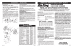
1. Tilt Fan Head back. Put Plastic Rear Grill on Motor. (Figure 1)
2. Align Triangular "∆" cut in Plastic Rear Grill with triangular post
on top of front Motor cover. Fully seat Plastic Rear Grill and
secure with Plastic Nut turning Clockwise. (Figure 2)
3. Slide Blade onto Motor Shaft. (Align groove on blade hub with
pin on motor shaft.) (Figure 3)
4. To secure Blade, screw Spinner onto Shaft Counter
Clockwise until tight on blade hub.
5. With fan head in upright position, align Ornament of Front Grill
so it is horizontal. Insert bottom of Front Grill into Plastic Rear
Grill. Tab at the bottom of Plastic Rear Grill should fit between
spokes of Front Grill. Snap Front Grill into Plastic Rear Grill
beginning at the top and working down both sides.
Plastic
Rear Grill
Blade
MAINTENANCE
WARNING: ALWAYS UNPLUG THE CORD BEFORE MOVING
OR SERVICING THE FAN.
WARNING: DO NOT IMMERSE FAN IN WATER!
CLEANING: Use a soft cloth moistened with a mild soap solution, such as liquid dish washing detergent. Dry ALL PARTS COMPLETELY before reassembling. After any maintenance or servicing,
completely reassemble unit as described in this instruction manual
before reconnecting to the power supply.
CAUTION: Do not use gasoline, benzine, thinner, harsh cleaners, etc. as they will damage the Fan. NEVER use ALCOHOL
OR SOLVENTS.
LUBRICATION: Precision bearings are sealed at the factory for life
and will not require any further lubrication.
STORAGE: Store the Fan, with these instructions, in a cool, dry
place.
SERVICING: All other servicing, with the exception of general
user-maintenance, should be performed by an authorized service
representative.
Pin
Plastic Rear
Grill
Motor
Plastic Nut
Spinner
Figure 1
Front
Grill
Figure 2
MANUAL DE INSTRUCCIONES DE OPERACIÓN Y PARTES
Figure 3
Groove
Pin
16
REPLACEMENT PART LIST
14
13
NO.
1
2
3
4
5
6
7
8
9
10
11
12
13
14
15
16
17
18
19
17
7
.
DESCRIPTION
4DA35B/9102B 4DA36B/9106B
Motor
Rotary Switch
Crimp Connect
Elevation Spring
Ratchet Plate
Neck Bolt
5/16-24 Hex Nut
Stand
Switch Knob
Bottom Plate
Power Supply Cord w/Plug
Front Grill
Spinner
Fan Blade
Plastic Nut
Plastic Rear Grill
Grill Ornament
Rubber Foot
Screw #8 X 9/16 PPH
02035053
02055087
7091854
02010162B
02090521
02090033
2010540P
2010131
2010313
02050009FPB
02096217
2010093
2010008
2010359P
2011212
02010381A
2010415
2090039
Qty
QTY
1
5
PART NO. FOR MODEL
REF
12
9
2
8
11
02035052
02055087
7091854
02090586
02010162B 02090521
02090033
2010541
2010131
2010315
02050009FPB 020962141 2010093
2011013
2010359P
2011200M
02010381A 2010415
2090039
1
1
1
1
1
1
1
1
1
1
1
1
1
1
1
1
1
2
1
10
19
18
Rev. F 10/09
LEA Y GUARDE ESTAS INSTRUCCIONES
LÉALAS CUIDADOSAMENTE ANTES DE INTENTAR ARMAR, INSTALAR, OPERAR O DAR MANTENIMIENTO AL PRODUCTO DESCRITO.
PROTÉJASE A SÍ MISMO Y A LOS DEMÁS OBSERVANDO TODA LA INFORMACIÓN SOBRE SEGURIDAD. ¡NO SEGUIR LAS INSTRUCCIONES PODRÍA RESULTAR EN LESIONES PERSONALES Y/O DAÑOS A LA PROPIEDAD!
GUARDE LAS INSTRUCCIONES PARA REFERENCIAS FUTURAS.
electricista calificado, utilizando exclusivamente alambre de
DESCRIPCIÓN
cobre.
®
Los Ventiladores Oscilantes Air King de 12” (30,5 cm) y 16” (40,6
ADVERTENCIA: NO SE RECOMIENDA EL USO DE UN ADAPTADOR DE
cm) vienen equipados con un motor de funcionamiento silencioso y
TRES A DOS ESPIGAS. LA CONEXIÓN INDEBIDA PODRÍA CREAR EL
RIESGO DE SER ELECTROCUTADO. EL USO DE TALES ADAPTADORES
una hélice de tres aspas. El ventilador es potenciado por un motor
NO ESTÁ PERMITIDO EN CANADÁ.
capacitador de hendidura permanente y prelubricado con un cable
ADVERTENCIA: Este enchufe es una medida de seguridad. Para
eléctrico 18/3 de 6 pies (1.8 m) de largo. Las parrillas del ventilador
reducir el riesgo de incendio, choque eléctrico y lesiones
cumplen con los requisitos de OSHA. Equipo aprobado por ETL.
personales, no quite, ni reemplace, ni repare o altere el
enchufe que se provee originalmente. Si el VENTILADOR no
funciona correctamente, puede deberse al dispositivo de
seguridad incorporado en este enchufe.
Especificaciones
Motor..........................................120V, 60Hz (12")(30,5 cm)
...................................................120V, 60Hz (16")(40,6 cm)
Tamaño de paletas...................... 12" (30,5 cm) Modelo (4DA35B/9102B)
................................................... 16"(40,6 cm) Modelo (4DA36B/9106B)
Velocidades...............................3 velocidades
Control.......................................Perilla Rotatoria
Distribución del flujo de aire.....90˚
8. De ser posible, evite el uso de cables de extensión. Si debieran
usarse, minimice el riesgo de sobrecalentamiento procurando que
estén aprobados por UL. Nunca use un solo cable de extensión
para hacer funcionar más de un Ventilador.
9. No haga funcionar ningún Ventilador con un cable o enchufe
dañado o después de que el ventilador presente algún
desperfecto o haya sido dejado caer o sufriera cualquier tipo
de daño.
10.No introduzca ni permita que se introduzcan dedos u objetos
extraños en ninguna abertura de ventilación o escape, puesto
que podría provocar un golpe de electricidad, incendio, o daños
al ventilador. No bloquee ni manipule el Ventilador de ninguna
manera mientras esté en funcionamiento.
11.Siempre coloque el Ventilador sobre una superficie, estable,
plana y horizontal mientras esté en funcionamiento, para evitar
la posibilidad de que el Ventilador se dé vuelta. Ubique el cable
eléctrico de tal modo que el ventilador u otros objetos no
descansen sobre él. No disponga el cable eléctrico debajo de
alfombras. No cubra el cable eléctrico con tapetes, alfombras
continuas u objetos similares. Coloque el cable eléctrico fuera del
paso de las personas y donde nadie se tropiece con el mismo.
12.Este Ventilador no ha sido diseñado para usarse en lugares mojados
o húmedos. Nunca coloque un Ventilador donde quepa la posibilidad
de que caiga en una bañera u otro recipiente con agua.
13.No use el Ventilador en exteriores.
14.Este Ventilador no es adecuado para usar en instalaciones
de agricultura incluyendo áreas donde se almacene ganado,
aves de corral u otros animales. Por favor consulte el Articulo
547-7 (2008) del Código Eléctrico Nacional (NEC), o los códigos
o normas estatales o locales aplicables con relación a los
requisitos eléctricos para edificios destinados a las agricultura.
ESTE VENTILADOR NO CUMPLE CON LOS REQUISITOS DEL
ARTICULO 547-7 DEL NEC (2008).
15.Este Ventilador no es adecuado para usar en lugares peligrosos.
Por favor consulte el Artículo 500 del Código Eléctrico Nacional
(NEC), o los códigos o normas estatales o locales aplicables
con relación a los requisitos eléctricos para lugares peligrosos.
ESTE VENTILADOR NO CUMPLE CON LOS REQUISITOS DEL
ARTICULO 500 (2008).
ADVERTENCIA: DISMINUYA EL RIESGO DE INCENDIO O GOLPES
DE ELECTRICIDAD – NO USE ESTE VENTILADOR CON ARTEFACTOS
DE CONTROL DE VELOCIDAD EN ESTADO SÓLIDO.
MODELO
4DA35B/9102B
4DA36B/9106B
VELOCIDAD ALTA MEDIA BAJA ALTA MEDIA BAJA
1330
CFM
930
780 620 1710 1500
M /s
0.43 0.37 0.29 0.80
0.71 0.63
3
1450
0.40
39
45
1300
0.30
35
41
1090
0.27
32
36
1545
0.71
77
53
1394
0.54
65
49
1244
0.48
57
44
INFORMACIÓN GENERAL DE SEGURIDAD
15
6
3
MODELO 4DA35B/9102B 12" (30,5 cm)
MODELO 4DA36B/9106B 16" (40,6 cm)
RPM
Amps
Watts
dB A
Figure 3
4
VENTILADORES OSCILANTES
2
2084067
Al usar aparatos eléctricos, las precauciones básicas de
seguridad deberan siempre de seguirse para reducir el
riesgo de incendio, choque eléctrico, y daño a personas,
incluyenda las siguientes.
1. Lea todas las instrucciones antes de utilizar el Ventilador.
2. Cerciórese de que la fuente de poder sea compatible con las
demandas eléctricas del Ventilador.
3. Use este Ventilador sólo en la forma que se describe en el
manual. Cualquier otro uso no recomendado por el fabricante
podría ocasionar un incendio, golpes de electricidad o lesiones a
personas.
4. Desenchufe el cable eléctrico antes de instalar, proporcionar
servicio o mover el Ventilador.
ADVERTENCIA: NO DEPENDA DEL INTERRUPTOR DE ENCENDIDOAPAGADO COMO EL ÚNICO MEDIO PARA DESCONECTAR LA POTENCIA
AL INSTALAR O PROPORCIONARLE SERVICIO AL VENTILADOR.
DESENCHUFE SIEMPRE EL CABLE ELÉCTRICO.
5. Este Ventilador NO debe usarse en ubicaciones potencialmente
peligrosas, tales como en ambientes inflamables, explosivos,
cargados de sustancias químicas o húmedos.
6. NO use el Ventilador en o cerca de una ventana. La lluvia puede
generar riesgos eléctricos.
7. El cordón eléctrico está equipado con una clavija a tierra de
tres espigas que tiene que ser enchufada a un receptáculo del
mismo diseño. Bajo ninguna circunstancia deberá cortarse la
espiga a tierra de la clavija. De existir un receptáculo de pared
de dos espigas, deberá reemplazarse por uno de tres espigas
debidamente puesto a tierra e instalado de conformidad con
el Código Nacional de Electricidad y todos los códigos y
ordenanzas locales aplicables. El trabajo deberá hacerlo un
Rev. F 10/09
3
CONSERVE ESTAS
INSTRUCCIONES
2084067