1
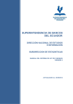
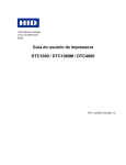
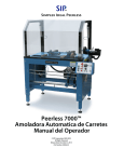
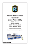
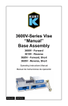
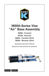
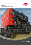
MANUAL DE INSTRUCCIONES
VENTILADOR DE PISO (16”)
AB-4917
ESTIMADO CLIENTE
Con el fin de que obtenga el mayor desempeño de su producto, por favor lea este manual de
instrucciones cuidadosamente antes de comenzar a utilizarlo, y guárdelo para su futura referencia.
Si necesita soporte adicional, no dude en escribir a: [email protected]
ÍNDICE
DESCRIPCIÓN .......................................................................................................................................... 2
ENSAMBLAJE DE LA COLUMNA ........................................................................................................... 2
INSTRUCCIONES DE ENSAMBLAJE ...................................................................................................... 3
INSTRUCCIONES DE OPERACIÓN DEL VENTILADOR ........................................................................ 3
INSTRUCCIONES DE SEGURIDAD ......................................................................................................... 3
LIMPIEZA Y MANTENIMIENTO ................................................................................................................ 3
DIAGRAMA DE CIRCUITOS ..................................................................................................................... 4
PRECAUCIÓN
RIESGO DE CHOQUE
ELÉCTRICO , NO ABRA
Precaución: Para reducir el riesgo de choque eléctrico, no
retire la cubierta, no hay partes manipulables por el usuario al
interior de la unidad.
Refiera todo mantenimiento o
intervención técnica a personal técnico calificado.
Este símbolo indica la existencia de voltaje peligroso al
interior de esta unidad, que constituye un riesgo de choque
eléctrico.
Este símbolo indica que hay importantes instrucciones de
operación y mantenimiento en la literatura que acompaña a
esta unidad.
LÍNEAS DE SERVICIO AL CLIENTE PREMIER
Venezuela:
Panamá:
Sitio Web:
E-mail:
0800 – ELECTRIC (353-2874)
300-5185
www.premiermundo.com
[email protected]
NOTA
Nos reservamos el derecho de modificar las especificaciones, características y/u operación de este
producto sin previo aviso, con el fin de continuar las mejoras y desarrollo del mismo.
P-1
DESCRIPCIÓN
1. Protector frontal
2. Tuerca retenedora
3. Aspas del ventilador
4. Tuerca de bloqueo
5. Protector posterior
6. Eje del motor
7. Carcasa del motor
8. Cuello
9. Caja de control
10. Tornillo
11. Polo interno
12. Anillo de ajuste de altura
13. Polo superior
14. Base
ENSAMBLAJE DE LA COLUMNA
Retire la base y la columna del empaque y
suelte la tuerca de plástico. Fije la columna en
la base utilizando la tuerca de plástico.
Desatornille el tornillo de ajuste. Monte el
ornamento de la columna y ajuste a la altura
deseada. Luego atornille el tornillo de ajuste
de altura para apretar el polo de extensión.
1. Una la columna a la base con 4 tornillos
como se muestra en la figura.
2. Retire el anillo de ajuste de altura.
3. Deslice el ornamento hacia abajo de la
columna para descansar la base.
4. Hale el tubo de extensión y coloque de
nuevo el anillo de ajuste de altura.
Nota: El anillo de ajuste de altura debe estar
completamente seguro antes de ensamblar la
sección del motor a la base.
P-2
Apretar
Anillo de ajuste
de altura
Cuatro tornillos
Ornamento de la base
Base
INSTRUCCIONES DE ENSAMBLAJE
1. Desatornille el girador en el sentido de las manecillas del reloj y la tuerca en el sentido contrario de
las manecillas del reloj para quitar ambos.
2. Coloque el protector posterior en la posición adecuada.
3. Atornille la tuerca plástica con firmeza para unir el protector posterior.
4. Deseche la funda de plástico en el eje del motor.
5. Coloque las aspas del ventilador en el eje del motor hasta que alcance el pin retenedor.
6. Atornille el girador en el eje del motor en el sentido contrario a las manecillas del reloj a las aspas.
7. Monte el protector frontal y una ambos protectores utilizando los clips.
INSTRUCCIONES DE OPERACIÓN DEL VENTILADOR
1. REGULADOR DE VELOCIDAD
La velocidad se controla presionando los botones del regulador de velocidad en la parte superior de la
unidad. Hay 4 botones: 0-apagado, 1-bajo, 2-medio, 3-alto.
2. TEMPORIZADOR
Gire el botón del temporizador a la posición que desee. El ventilador se detendrá cuando este tiempo se
cumpla. El período más largo para ajustar es de 120 minutos. Recuerde que el ventilador no puede
funcionar si el temporizador está en la posición 0.
3. OSCILACIÓN
Para activar y desactivar esta función presione y hale el botón de oscilación.
4. INCLINACIÓN
Para ajustar la inclinación del aire mueva manualmente los protectores.
INSTRUCCIONES DE SEGURIDAD
•
•
•
La unidad no debe ser utilizada por niños o personas con capacidades físicas o mentales reducidas,
a menos que tengan estricta supervisión.
Si el cable de poder está dañado no utilice la unidad.
No intente reparar la unidad usted mismo. Remita toda revisión, mantenimiento y reparación a
personal de servicio técnico calificado.
LIMPIEZA Y MANTENIMIENTO
•
•
•
•
Antes de comenzar la limpieza desconecte el cable de poder.
Mantenga las rejillas de circulación de aire limpio de polvo.
Utilice una prenda húmeda suave con un poco de detergente para limpiar el ventilador. No utilice
productos abrasivos ya que pueden dañar el acabado.
No permita que el agua u otros líquidos entren al interior del ventilador.
P-3
DIAGRAMA DE CIRCUITOS
Voltaje
Potencia
AC110V/60Hz
50W
Temporizador
Capacitor
Motor
Interruptor de Velocidad
Cable de poder
P-4
INSTRUCTION MANUAL
16” STAND FAN
AB-4917
DEAR CUSTOMER
In order to achieve the best performance of your product, please read this instruction manual carefully
before using, and keep it for future reference.
If you need extra support, please write to [email protected]
CAUTION
RISK OF ELECTRIC
SHOCK, DO NOT
OPEN
Caution: To reduce the risk of electric shock do not open
this device, there are not serviceable parts for customers.
Please refer any maintenance or repair to qualified
personnel.
This sign means the existence of dangerous voltage at
the inside of the unit, which states a risk of electric shock.
This sign means that there are important instructions of
operation and handling in the manual that comes with this
device.
PREMIER CUSTOMER SERVICE
Venezuela:
Panama:
Website
E-mail:
0800 – ELECTRIC (353-2874)
300-5185
www.premiermundo.com
[email protected]
NOTE
This unit may be submitted to changes in specifications, characteristics and/or operation without prior
notice to the user, in order to continue improving and developing its technology.
P-1
TECHNICAL PARAMETER
RATED VOLTAGE(V)
RATED FREQUEN (Hz)
INPUT POWER (W)
AC110V
60Hz
50W
PARTS NAME
Description
1. Front guard
2. Retaining nut
3. Fan blade
4. Locking nut
5. Rear guard
6. Motor shaft
7. Motor housing
8. Neck
9. Control box
10. Screw
11. Internal pole
12. Height adjustment ring
13. Outer pole
14. Base
COLUMN ASSEMBLY INSTRUCTIONS
Take the base and column parts from the packing box and loose the plastic nut. Fix the column on the
base plate using the plastic nut. Unscrew the height adjust-ing knob. Mount the column ornament, and
move to the desired height. Then screw the height adjusting knob to tighten the extension pole.
P-2
COLUMN ASSEMBLY
1.
2.
3.
4.
Attach column to stand with 4 screws as shown.
Unscrew / take out height adjustment ring.
Slide stand ornament down the column to rest on stand.
Pull out the extension pipe and screw / fasten the height
adjustment ring back.
CAUTION: Height adjustment ring must be fully
fastened before the assembly of the motor section
to the stand.
ASSEMBLY INSTRUCTIONS
1.
2.
3.
4.
5.
6.
7.
Unscrew the spinner clockwise and the nut counter- clockwise to remove both of them.
Set the rear guard in the proper position with handle up.
Screw on plastic nut tightly to attach rear guard.
Discard plastic sleeve on motor shaft.
Install the fan blade onto the motor shaft until it reaches the retaining pin.
Screw spinner onto motor shaft counter anti-clockwise to blade.
Mount the Front Guard and join both Guards together using the Clips.
FAN OPERATING INSTRUCTIONS
1. SPEED REGULATOR:
Speed is controlled by pressing
Buttons of speed regulator on the
Top of body (4 buttons: 0—off, 1—low, 2—medium, 3—high).
2. TIMER
Turn the knob of timer to position which
Set the time you want. The fan will stop
When the time is over. The longest time set is 120 minutes. In case the timer is not use, set the timer
to “ON”
NOTES: The fan can not run if timer is on “0” position
3. OSCILLATING
To make / stop the fan head oscillate, push down / pull up the oscillating
4. TILT ADJUSTING:
P-3
To adjust the air flow upward or downward, push the guard lightly to the desired direction.
This appliance is not intended for use by persons (including children) with reduced. Physical, sensory
or mental capabilities, or lack of experience and knowledge, unless they have been given supervision or
instruction concerning use of the appliance by a person responsible for their safety.
Children should be supervised to ensure that they do not play with the appliance.
If the supply cord is damaged, it must be replaced by the manufacturer, its service agent or similarly
qualified persons in order to avoid a hazard.
MAINTENANCE INSTRUCTION
The fan requires little maintenance. Do not try to fix it by yourself. Refer it to qualified service personnel
if service is needed.
1. Before cleaning and assembling, do not plug the pins into the socket.
2. To ensure adequate air circulation to the motor. Keep vents at the rear of the motor housing away
from dust, fluff and etc. Do not disassemble the fan unless you have remove fluff.
3. Please wipe the exterior parts with a soft cloth soaking a mild detergent. Do not use any abrasive
detergent or solvents to avoid scratching the surface. Do not use any of the following as a cleaner:
gasoline, thinner, bending.
4. Do not allow water or any other liquid into the motor housing or interior parts.
CLEANING
1. Be sure to unplug from the electrical supply source before cleaning.
2. Plastic parts should be cleaned with a soft cloth moisten with mild soap. Thoroughly remove soap film
with dry cloth.
CIRCUIT DIAGRAM
Voltage : AC110V/60Hz , Power : 50W
P-4