1
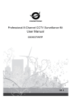
H.264 NETWORK Embedded NVR USER MANUAL NVR-V11 -1- Thank you for purchase our product. Please read this user manual carefully to ensure that you can use the device correctly and safely Important Safeguards and Warding: ◆ Do not place heavy objects on the NVR. ◆ Do not let any solid or liquid fall into or infiltrate the NVR. ◆ Please brush printed circuit boards,connectors,fans,machine box and so on regularly.Before the dust cleaning please switch off the power and unplug it. ◆ Do not disassemble or repair the NVR by yourself.Do not replace the components by yourself. Environment: ◆ Please place and use the NVR between 0℃ and 40℃.Avoid direct sunlight.Stay away from heat source. ◆ Do not install the NVR in the damp environment. ◆ Do not use the NVR in smoky or dusty environment. ◆ Avoid collision or strong fall. ◆ Please insure the NVR level installation in a stable workplace. ◆ Please install in ventilated place.Keep the vent clean. ◆ Use within the rating input and output scope. -2- CONTENT CONTENT..................................................................................................................................................................3 1 Open-package check and cable connections...................................................................................................4 1.1 Open-package check .....................................................................................................................................4 1.2 Front panel .................................................................................................................................................4 1.3 Rear panel .....................................................................................................................................................5 2 Basic operation......................................................................................................................................................5 2.1 Turn on ..........................................................................................................................................................5 2.2 Turn off .........................................................................................................................................................6 2.3 System Login ................................................................................................................................................6 2.4 Preview .........................................................................................................................................................6 2.5 Desktop shortcut menu..................................................................................................................................7 3 Main menu ...........................................................................................................................................................16 3.1 Record .........................................................................................................................................................16 3.2 Alarm Function ...........................................................................................................................................18 3.3 System setup ...............................................................................................................................................22 3.4 Advanced.....................................................................................................................................................36 3.5 Info..............................................................................................................................................................41 Appendix 1.Remote controller operation ............................................................................................................43 -3- 1 Open-package check and cable connections 1.1 Open-package check When you receive the NVR, please check first. First, please check whether there is any visible damage to the package appearance. The protective materials used for the package of the NVR can protect most accidental clashes during transportation. Then, please open the box and get rid off the plastic protective materials. Check whether there is any visible damage to the NVR appearance. At last, please open the machine crust and check the data wire in the front panel, power wire, the connection between the fan power and the main board. 1.1.1Front panel and rear panel The key function specification in the front panel and the interface specification in the real panel are in the specification. Please check the product type in the front panel whether is accordant with the product type you order. The label in the real panel is very important for the after service. Please protect it carefully. When you contact us for after service, please provide the product type and serial number in the label. 1.1.2.Check After open the cover,you should check if it has obvious damage trace,also please check the front panel data cable,power cord and motherboard's connection are loose or not. 1.2 Front panel The front panel of T series 1) STANDBY: Press to power the system standby. 2) IR Sensor: IR receiver for the remote control. 3) LED Indicators: Shows status of alarm, rec, power. 4) Channel/Numbers/Playback: Press buttons 0~9 to view the selected channel in full-screen; press buttons 0~9 to input passwords and user IDs; during playback, press the following: 5) : Increase reverse playback speed 1X, 2X, 4X 6) : Press to freeze playback to one frame, then press again to advance frame-by-frame 7) : Press to start playback -4- 8) : Press to slow playback speed by 1/2, 1/4, 1/8 9) : Press to increase forward playback speed 1X, 2X, 4X 10)MENU/ OK: Press to open/close the main menu.or confirm. 11)Navigation: Press the Navigation buttons to perform the following: •: In menus, press to confirm selections; in PTZ mode, press to change the navigation buttons to control the connected PTZ camera (not included) • • : Press to move cursor up; in PTZ mode, press to pan camera up : Press to move cursor down; in PTZ mode, press to pan camera down : Press to move cursor left; in PTZ mode, press to pan camera left • • : Press to move cursor right; in PTZ mode, press to pan camera right 12)USB: Connect a USB flash drive to the top port for data backup and firmware upgrades connect a USB mouse to the bottom port. 1.3 Rear panel The rear panel of T series (1) Video Output (2) Audio Output (3) VGA Output (4) HDMI Output (5) Network (6) USB (7) RS485 (8) Power 2 Basic operation Note: The button in gray display indicates nonsupport.and the picture is only for reference,please make the object as the standard 2.1 Turn on Plug the power supply and turn on the power supply switch. Power supply indicator light shining indicates turning on the video recorder. After the startup you will hear a beep. The default setting of video output is multiple-window output mode. If the startup time is within the video setting time, the timing video recording function will start up automatically. Then the video indicator light of corresponding channel is shining and the NVR is working normally. Note:1. Make sure that the input voltage corresponds with the switch of the NVR power supply. 2. Power supply demands: 220V±10% /50Hz. Suggest using the UPS to protect the power supply under allowable conditions. -5- 2.2 Turn off There are two methods to turn off the NVR. Entering [main menu] and choosing [turn off] in the [turn off the system] option is called soft switch. Pressing the power supply switch is called hard switch. Illumination: 1、Auto resume after power failure If the NVR is shut down abnormally, it can automatically backup video and resume previous working status after power failure. 2、Replace the hard disk Before replacing the hard disk, the power supply switch in the real panel must be turned off. 3、Replace the battery Before replacing the battery, the setting information must be saved and the power supply switch in the real panel must be turned off. The NVR uses button battery. The system time must be checked regularly. If the time is not correct you must replace the battery, we recommend replacing the battery every year and using the same battery type. Note: The setting information must be saved before replacing the battery otherwise information will lose. 2.3 System Login When the NVR boots up, the user must login and the system provides the corresponding functions with the user purview.There are three user settings. The names are admin, guest and default and these names have no password. Admin is the super user purview; guest and default’s permissions are preview and video playback. User admin and guest’s password can be revised, while their permissions can’t be revised; user default is the default login user whose permission can be revised but not its password. Picture 2.3 System Login Password protection: If the password is continuous wrong three times, the alarm will start. If the password is continuous wrong five times, the account will be locked. (Through reboot or after half an hour, the account will be unlocked automatically). For your system security, please modify your password after first login. 2.4 Preview You can right click mouse to choose the switch between the windows. The system date, time and channel name are shown in each viewing window. The surveillance video and the alarm status are shown in each window. -6- Table 2.4.0 Preview icon 1 Recording status 3 Video loss 2 Motion detect 4 Camera lock 1 2 3 4 Pic 2.4.1 Preview interface (1) (3) Channel name and status display,click “channel” can pack up Full screen display (2) Screen switch (4) on the next page turning,when choosing a non maximum number of channels,the operation can be carried out Note:It’s main stream’s resolution under single window,and it’s extra stream’s resolution under multi-screen. 2.5 Desktop shortcut menu In preview mode you can right click mouse to get a desktop shortcut menu,as the picture 2.2 shows.The menu includes: main menu, record mode, playback, PTZ control, High Speed PTZ, -7- Alarm Output,Output adjust, Logout, full screen(leave full screen). Non full screen full screen Picture 2.5.0 Shortcut Menu Note:When under non full screen display”full screen”,and when under full screen display”leave full screen”. 2.5.1 Main menu When you login, the system main menu is shown as below. Pic 2.5.1 Main menu 2.5.2 Playback There are two methods for you to play the video files in the hard disk 1.In the desktop shortcut menu 2.Main Menu>Record>playback Note: The hard disk which saves the video files must be set as read-write or read-only state. -8- 9 8 1 7 6 3 5 4 11 2 10 Pic 2.5.2.0 Video playback 1 Playback control 2 Operation hint 3 Record mode 4 5 Switch by time,file mode 6 File searching 7 Channel choosing 8 9 Storage device choosing 10 File information 11 Listed files 12 Time interval choosing Date choosing Time searching 【Listed files】Look up the listed files that accord with the searching criteria. 【File information】Look up the found file information. 【Playback control】See detail in below chart Button / Function Button Function Backward play Play/Pause -9- Slow forward Fast forward Previous frame Next frame Previous file Next file Round play Full screen Stop Table 2.5.2.1 Playback control key Note: play under frame by frame, the playback status should be paused firstly. 【Operation hint】show function of the key that cursor placed. Special functions: Local zoom:When the system is in single-window full-screen playback mode, you can drag your mouse in the screen to select a section and then left click mouse to realize local zoom. You can right click mouse to exit. Note: When current resolution of the channel is over Max resolution, to playback this channel, will show a Red “X”. 2.5.3 Record Control Please check current channel status: “○” means it is not in recording status, “●” means it is in recording status. You can use desktop shortcut menu or click [Main menu]> [Record]> [Record Conf] to enter the recording control interface. Pic 2.5.3 Record Mode 【Schedule】Record according to the configuration. 【Manual】Click the all button and the according channel is recording no matter the channel in any state. 【Stop】Click the stop button and the according channel stops recording no matter the channel in any state. 2.5.4 Alarm output Please check current channel status: “○” means it is not in alarming status, “●” means it is in alarming status. You can use desktop shortcut menu or click [Main menu]> [Alarm]> [Alarm output] to enter the - 10 - alarm output interface. Pic 2.5.4 Alarm output 【Configuration】Alarm is on according to the configuration. 【Manual】Click the all button and the according channel is alarming no matter the channel in any state. 【Stop】Click the stop button and the according channel stops alarming no matter the channel in any state. 2.5.5 PTZ control PTZ control,the digital channel need link PTZ, the remote device should connect with PTZ and with protocol correctly set also. Operation interface is as followed. The functions include: PTZ direction control, step, zoom, focus, iris, preset operation, tour,pattern, border, assistant switch, light switch,autopan and so on. Note1. Decoder A(B)line connects with NVR A(B)line. The connection is right. 2. Click [Main menu] >[System] >[PTZ Config] to set the PTZ parameters. 3. The PTZ functions are decided by the PTZ protocols. Pic 2.5.5.0 PTZ setup 【Speed】Set the PTZ rotation range. Default range: 1 ~ 8. 【Zoom】Click / button to adjust the zoom multiple of the camera. 【Focus】Click / button to adjust the focus of the camera . 【Iris】Click / button to adjust the iris of the camera. 【Hide】Current interface will be temporarily hidden after click it. 【Direction control】Control the PTZ rotation. 8 directions control is supportive.(4 directions in Front panel is supportive ) 【High speed PTZ】Full-screen show channel image. Left press mouse and control PTZ to rotate orientation. Left press mouse and then rotate the mouse to adjust the zoom multiple of the camera - 11 - 【Set】Enter the function operation menu. 【Page switch】Switch between different pages. Special functions: 1、Preset Set a location for the preset, calls the preset points, PTZ automatically turns to the setting position 1)Preset option Set a location for the preset, procedure is as follows: Step1: in Picture 2.5.5.0, click the Direction button will turn into preset position , click the Settings button to enter Picture 2.5.5.1. Step 2: click the Preset button , then write the preset points in the input blank, Step 3: click Settings button, return the Picture 2.5.5.0 Complete setup, that is the preset points and preset position corresponds. Clear Preset:Input preset points, click Remove button, remove the preset. Preset point input Preset button Pic 2.5.5.1 Preset Settings 2)Preset Point Calls In Picture2.5.5.0, click Page Switch button, enter PTZ control interface as shown in Picture2.5.5.2. In the input blank, write the preset points, then click Preset button, PTZ turn to the corresponding preset point. Value input blank Pic 2.5.5.2 PTZ control 2、Tour Multiple preset points connected tour ,the PTZ run around on the line 1)Tour Settings Tour is connected by multiple preset points, setting procedure is as follows: Step1: In Picture 2.5.5.0, the Direction key will turn PTZ to designated location ,click Settings button to enter Picture 2.5.5.3. - 12 - Step 2: click Tour buttons, then input proper value into the Preset points and Patrol No blank, click Add Preset Points button, complete setting (also can add and delete tour preset which has been set up) Step 3: repeat step1 and step2 , until set out all the preset designated Cruise lines. Remove Preset:Please input preset value in the blank, click Remove Preset button, then remove the preset points. Remove Tour:Input the number of tour, click Remove tour button, then remove the tour set。 Preset Points Blank Tour Button Time interval Patrol number Blank Pic 2.5.5.3 Tour setup 2)The Calls of Tour In Picture 2.5.5.0, click Page Switch button, enter PTZ control menu as shown in Picture 2.5.5.2. Please input the number of tour in the value blank, then click tour button, PTZ begins to work on the tour patrol. Click Stop button to stop tour. 3、Scan PTZ also can work on the preset scan line repeatedly. 。 1)Scan setup Setting steps: Step1: In Picture 2.5.5.0, click Setup button ,enter Picture 2.5.5.4; Step2: Click Scan button,the input proper value in the scan value blank; Step3:Click Start button, enter Picture2.5.5.0,here you can set the following items: Zoom,Focus,Aperture,Direction and so on. Click Setup button to go back Picture 2.5.5.4 Step4: Click End button to complete setup.Click the right button of the mouse to exit. Scan value blank Scan Button Pic 2.5.5.4 Scan Setup 2)Scan Calls In Picture2.5.5.0, click Page Switch button, then enter PTZ control menu as shown in Picture 2.5.5.2. Please input the number of scan in the value blank , then click Scan button,PTZ begins to work on the scan line . Click Stop button to stop. - 13 - 4、Boundary Scan In a horizontal line,set up a line,call scan,PZT repeat operation according to the route 1)Boundary Scan setup Set a period of horizontal curve for PTZ search path,the steps are as follows: Step1:In Picture 2.5.5.0, click Direction button to turn the PTZ to preset direction, then click Setup button enter Picture 2.5.5.5, select the left boundary, return to Picture 2.5.5.0; Step2 : Please click direction arrows to adjust PTZ direction, click Setup button enter Picture2.5.5.5, then select the right boundary ,return to Picture2.5.5.0; Step3: Complete setup, that is the position of left and right boundary Note:when the left and right scan in one horizontal,the PTZ will cycle rotate from left scan along the reverse direction to the right scan. When the left and right scan not in the same horizontal ,the PTZ will regard the end of horizontal line which connect to left scan as right scan,cycle rotate from left scan along the reverse direction to the right scan. Left/Right scan setting button Line scan button border Pic 2.5.5.5 Boundary Scan Setup 2)Boundary Scan Calls In Picture2.5.5.0, click Page Switch button, then enter PTZ control menu as shown in Picture 2.5.5.2. Please input the number of scan in the value blank , then click Scan button,PTZ begins to work on the scan line . Click Stop button to stop. 5、Horizontal Rotating Click Horizontally Rotating button, PTZ begins to rotate horizontally (relative to the original position of the camera). Click the Stop button to stop. 6、Rotate Click on horizontal Rotating button, PTZ turn around. 7、Reset PTZ restart, all the data clears to 0. 8、Page Shift In Picture 2.5.5.2, click Page Switch button into Picture 2.5.5.6, setting auxiliary function. Auxiliary number corresponding to auxiliary switch on the decoder. - 14 - Pic 2.5.5.6 Auxiliary Function Control 【Direct Aux open】 choose auxiliary equipment, select Open or Close button, switch control; 【 Aux Num open 】 The operation of corresponding auxiliary switch according to PTZ agreement; 【Page Switch】In Picture 2.5.5.6,click Page Shift button enter the Picture 2.5.5.5 PTZ Main Menu , the menu itself can be control by the menu control buttons 2.5.6 Output Adjust Adjust TV output area parameters. You can use the desktop shortcut menu or enter [Main menu]> [Advanced]> [Output Adjust]. Pic 2.5.6 Output Adjust 2.5.7 Logout Logout, shut down the system or reboot up. You can use the desktop shortcut menu or enter [main menu]. - 15 - Pic 2.5.7 Logout 【logout】Quit the menu. Offer password next entrance. 【shut down】Quit the system. Turn off the power supply. When press the shut down button, there is schedule hint. After three seconds, the system is shut down. Cancel midway is of no effect. 【reboot】Quit the system. Reboot up the system. 2.5.8 Full screen(leave full screen) According demand to choose full screen or non full screen. 3 Main menu 3.1 Record Operations related to record, including: Record, Playback, Backup 3.1.1 Record Configuration Set the recording parameters in the surveillance channel. The system is set 24 hours consecutive recording in the first startup. You can enter [Main Menu]> [Record> [Record Conf] to set. Note:There is at least one read-write hard disk.(refer to chapter 3.5.1) Picture 3.1 Record Conf 【Channel】Choose the corresponding channel number to set the channel. Choose the all option to set the entire channels. - 16 - 【Redundancy】Choose the redundancy function option to implement the file double backup function.Double backup is writing the video files in two hard disks. When you do the double backup, make sure that there are two hard disks installed. One is read-write disk and the other is redundant disk. (refer to 3.5.1) 【Length】Set the time length of each video file. 60minutes is default value. 【Pre-Record】Record 1-30 seconds before the action. (time length is decided by the code stream) 【Record mode】Set video state: schedule, manual or stop. Schedule: Record according to the set video type (common, detection and alarm)and time section. Manual: Click the button and the according channel is recording no matter the channel in any state. Stop: Click the stop button and the according channel stops recording no matter the channel in any state. 【Period】Set the time section of common recording, The recording will start only in the set range. 【Record type】Set recording type: regular, detection or alarm. Regular: Perform the regular recording in the set time section. The video file type is “R”. Detect: Trigger the “motion detect”, “camera mask” or “video loss” signal. When above alarm is set as opening recording, the “detection recording” state is on. The video file type is “M”. Alarm: Trigger the external alarm signal in the set time section. When above alarm is set as opening recording, the “detection recording” state is on. The video file type is “A”. Note: Refer to chapter 3.3 to set corresponding alarm function. 3.1.2 Playback Refer to chapter 2.5.2. 3.1.3 Backup You can backup the video files to external storage through setup. Note:The storage must be installed before the file backup. If the backup is terminated, the already backup can playback individually. Picture 3.1.3 detect storage device 【Detect】Detect the storage connected with the NVR such as hard disk or universal disk. - 17 - 【Backup】Click backup button and the dialog box is popped up. You can choose the backup file according to the type, channel and time. Picture 3.1.3.1 Backup Remove:Clear the file information. Add:Show the file information satisfying the set file attributes. Backup format:configurate the backup file format,according to require,can choose Start/pause:Click the play button to start the backup and click the pause button to stop the backup. Note:During backup you can exit the page layout to carry out other functions. 【Burning】the file will be burned synchronously after click it. 【Erase】Choose the file to delete and click erasure to delete the file. 【Stop】Stop the backup. 3.2 Alarm Function Alarm functions include: motion detect,video blind, video loss, alarm input and alarm output, abnormality. 3.2.1 Motion Detect When system detects the motion signal that reaches the set sensitivity, the motion detect alarm is on and the linkage function is turned on. Note: "Advanced" button is the same as right click. - 18 - Pic 3.2.1.0 motion detect 【Channel】Choose the set motion detect channel. 【Enable】■ means that the motion detect function is on. 【Period】Trigger the motion detect signal in the set time section. You can set according to week or set uniformly. Each day is divided into four time sections.■ means the set valid. Pic 3.2.1.1 set the time section 【Interval】Only one alarm signal is turned on even there are several motion detect signals in the set interval. 【Alarm output】Start the external equipment of corresponding linkage alarm when the motion detect alarm is turned on. 【Delay】Delay a few moments and stop when the alarm state is turned off. The range is 10~300 seconds. 【Record channel】Choose the recording channel (multiple option supportive). Trigger the video signal when the alarm is turned on. Note:Set in the [Record Conf] and perform the linkage recording. Start detecting video files in the corresponding time section. 【Tour】■ means that the selective channel is single window alternate patrol preview. The interval is set in the [Main Menu]>[System] > [Tour]. 【PTZ Activation】Set the PTZ activation when the alarm is turned on. Note:to link PTZ, need go [Shortcut menu]->[PTZ control] to set preset point, tour & interval time - 19 - etc. Pic 3.2.1.2 PTZ linkage 【Delay】When alarm is over,recording will last some seconds(10~300sec),then stop. 【Show message】Pop the alarm information dialog box in the local host computer screen. 【Send EMAIL】■ means sending an email to user when the alarm is turned on. Note:Set in the [NetService] and send email. 【FTP upload】to tick it, the video & picture of related record channel & snapshot channel will be uploaded to assigned position. Note:FTP upload need be set at [Netservice] 【Buzz】When alarm happens, device will come out with buzz. 3.2.2 Video Blind When the video image is influenced by the environment such as bad brightness or reaching the set sensitivity parameter, the video blind function is turned on and the linkage function is turned on. Note:Both of the NVR and the connected device need to enable video blind function ,then it can works. "Advanced" button is the same as right click. Pic 3.2.2 video blind Set method: refer to chapter 3.3.1. Motion detect. - 20 - 3.2.3 Video Loss When the equipment can not obtain the channel video signal, the video loss alarm is turned on and the linkage function is turned on. Note:Both the NVR and the connected device need to enable this function ,then it can works. "Advanced" button is the same as right click. Pic 3.2.3 Video loss Set method: refer to chapter 3.3.1. Motion detect 3.2.4 Alarm input When the equipment obtains the external alarm signal, the alarm function is turned on. Note: "Advanced" button is the same as right click. Pic 3.2.4 Alarm input Set method: refer to chapter 3.3.1. Motion detect - 21 - 3.2.5 Alarm output Refer to chapter 2.5.4. 3.2.6 Abnormal Analysing and inspecting current software and hardware of the device: When some abnormal events happen,the device will make a relative answer such as show message and buzzer. Pic 3.2.6 Abnormal handing 【Event Type】 selecting abnormity you want to inspect 【Enable】 Select it to make sure abnormal function workable 【Show message】 Automatically alarm cue dialog box come out of the main screen 【Buzzer】 Device will have one long nosie “di” while alarm is happening 3.3 System setup Set the system parameters such as:General,Network, Net service,GUI display,PTZ configuration/RS485 ,RS232,Tour and digital。 3.3.1 General Pic 3.3.1.0 general setup 【System time】Set the system data and time. 【Date format】Choose the data format: YMD, MDY, DMY. - 22 - 【Date Separator】Choose list separator of the data format. 【Time Format】Choose time format: 24-hour or 12-hour. 【Language】Support 29 language at present:S- Chinese,T-Chinese,English,Farsi,Finnish,French, Greek,Hungarian, Italian, Japanese, German, polish, Portuguese, Russian, Spanish, Thai, Turkish, Vietnamese, Romania, Brazil,Indonesia, Swedish, Arabic, Bulgarian, Czech, Hebrew, etc. 【HDD full】Choose stop record: Stop recording when the hard disk is full. Choose overwrite: Cover the earliest recording files and continue recording when the hard disk is full. 【DVR No.】Only when the address button in the remote controller and the corresponding NVR number is matched, the remote operation is valid. 【Video Standard】PAL or NTSC. 【Auto Logout】Set the latency time in 0-60. 0 means no latency time. 【Machine Name】Can setting the device's name. 【DST】Choose the summer time option and pop the dialog box as followed. Pic 3.3.1.1 DST (week) Pic 3.3.1.2 DST (date) 3.3.2 Network setup Pic 3.3.2 Network setup - 23 - 【Net Card】You can choose cable network card or wireless network card. 【DHCP Enable】Obtain IP address automatically(not suggested) Note:DHCP server is pre-installed. 【IP address】Set the IP address. Default: 192.168.1.10. 【Subnet mask】Set the subnet mask code. Default: 255.255.255.0. 【Gateway】Set the default gateway. Default: 192.168.1.1. 【DNS setup】Domain Name Server. It translates the domain name into IP address. The IP address is offered by network provider. The address must be set and reboot then it works. 【Media port】Default: 34567. 【HTTP port】Default: 80. 【HS Download】 【Transfer Policy】There are three strategies: self-adaption, image quality precedence and fluency precedence. The code stream will adjust according to the setup. Self-adaption is the tradeoff between the image quality precedence and fluency precedence. Fluency precedence and self-adaption are valid only when the assistant code stream is turned on. Otherwise image quality precedence is valid. 3.3.3 NetService Choose the network service option and click the set button to configure the advanced network functions or double click the service button to configure the parameters Pic 3.3.3.0 Netservice 【PPPoE setup】 Pic 3.3.3.1 PPPOE Enable:Reverse■ means choose,setting can become effective. Input the user name and password that ISP(Internet service provider)provides. After saving it - 24 - reboot up your system. Then the NVR will build a network connection based on PPPoE. The IP address will change into dynamic IP address after above operation is well done. Operation:After PPPoE dialing successfully look up the IP address in the [IP address] and obtain the current IP address. Then use this IP address to visit the NVR through user port. 【NTP setup】 Pic 3.3.3.2 NTP setup The NTP server must be installed in the PC. Enable:Reverse■mean choose,setting can become effective. Host computer IP:Input the IP address installed NTP server. Port:Default: 123. You can set the port according to NTP server. Time zone:London GMT+0 Berlin GMT +1 Cairo GMT +2 Moscow GMT +3 New Delhi GMT +5 Bangkok GMT +7 Hongkong Beijing GMT +8 Tokyo GMT +9 Sydney GMT +10 Hawaii GMT-10 Alaska GMT-9 Pacific time GMT-8 American mountain time GMT-7 American mid time GMT-6 American eastern time GMT-5 Atlantic time GMT-4 Brazil GMT-3 Atlantic mid time GMT-2. Update Period:The same with the NTP server check interval. Default: 10minutes. 【EMAIL setup】 If the alarm is turned on or the alarm linkage photos are taken, send an email about the alarm information and the photos to appointed address. Pic 3.3.3.3 EMAIL setup SMTP server:Email server address. It could be an IP address or domain name. Domain name can be translated only it is the correct DNS configuration. Port:Email server port number. SSL:Decide whether using Secure Socket Layer protocol to login. User Name:Apply the email server user name. Password:Input the password corresponding to the user. Sender:Set the email sender address. Receiver:Send the email to appointed receivers when the alarm is turned on. You can set three - 25 - receivers at most. Title:You can set as you wish. 【IP Filter setup】 When choosing the white list, only the listed IP address can connect the NVR. The 64 IP addressed are supportive in the list. When choosing the black list, the listed IP address can not connect the NVR. The 64 IP addressed are supportive in the list. You can delete the set IP address by √ in the options. Note:When the same IP address is in the white and black list at the same time, the black list precedence is higher. Pic 3.3.3.4 IP filter setup 【DDNS】 Pic 3.3.3.5 DDNS setup It is the abbreviation of dynamic domain name server. Local domain name:Provide the domain name registered by DDNS. User name:Provide the account registered by DDNS. Password:Provide the password registered by DDNS. When the DDNS is successfully configured and start, you can connect the domain name in the IE address column to visit. Note:The DNS setup must be configured correctly in the network setup. 【FTP setup】 FTP is available only when alarm happens,or alarm activates record and snapshot,it will upload related record and snapshot pictures to FTP server. - 26 - Pic 3.3.3.6 FTP setup 【Enable】Click Enable,then all settings will be available 【Server IP】IP address for FTP server 【Port】Domain Port of FTP,default 21 【User Name】User name of FTP 【Password】Password of user 【Anonymous】:enable anonymous,no need setting user name and password 【Max File Length】Max length for upload files at every packed,default 128M 【Dir Name】:The directory of upload file. Note: The user should be with authority to upload files. 【ARSP】 Startup DDNS server to add devices and manage it in the DDNS server Pic 3.3.3.7 ARSP setup 【Type】choose "DNS" 【Enable】■ means it is chosen 【Sever IP】IP address of DDNS server 【Port】: Port No. of device, related DDNS server listen port 【User name】the user name that device can log in DDNS server 【Password】the password related to the user name. 【Refresh cycle】Time interval between device and DDNS when chynchronously. Note: Please set up server before using DDNS. 【Alarm center】 When alarm occurring, report alarm information to alarm server. - 27 - Pic 3.3.3.8 Alarm center setup 【Protocol type】GENERAL 【Enable】To tick it means enable. 【Server IP】IP address of Alarm Server 【Port】Device Port No. 【Alarm Report】Tick it means to report alarm information to server. 【Log Report】Tick it, means to report log to server. 【Wireless Config】 ADSL through 3G net card,use CMS to visit and configuration the device Pic 3.3.3.9 Wireless setup 【Enable】Choose Enable to make all settings available 【Type】Dial type,default AUTO 【Wireless AP】3G access point 【Dial Number】3G Dial Number 【User Name】User name of 3G 【Password】Password of dial user 【IP Address】IP address,got from dial 【Mobile Monitor Setup】 To visit the device by mobile,please make a router mapping of this port and use mobile software to monitor and operate it by protocol. - 28 - Pic 3.3.3.10 Mobile Monitor Setup 【Enable】 Select it to make sure abnormal function workable 【Port】 It’s a port of mobile monitoring which you need to make a router mapping of if want to visit it by mobile 【UPNP】 UPNP protocol is to realize auto port forwarding on router, precondition of using this function is to make sure the UPNP function of router is enabled. Pic 3.3.3.11 UPNP setup 【Enable】Choose Enable to make sure all UPNP settings available 【HTTP】Route will automatically distribute HTTP port for the device,when IE viewing,it need this port 【TCP】Router will automatically distribute TCP port for the device,when monitoring via CMS,it need this port. 【Mobile Port】Router will automatically distribute Mobile Port for the device,when mobile monitor,it need this port. 【WIFI】 NVR connect to wireless router via WIFI module, then to visit it through IP address, the precondition of using this function is to make sure the NVR have connected with WIFI modern. Pic 3.3.3.12 WIFI setup 【Search】:click【search】to search all the available wireless device in current range. - 29 - 【enable】:tick it to enable firstly, then go for further setting. 【auto obtain IP address】:tick it to enable, device will auto obtain a WIFI IP. 【SSID】:wireless LAN name, auto match to the wireless device u connected. 【Password】:wireless network password of router; 【IP address】: to set the IP address of device, default is 192.168.1.12 【subnet mask】:set subnet mask of device, default is 255.255.255.0 【gateway】:set gateway of device, default is 192.168.1.1 【RTSP】 To do surveillance via cross-browser (Safari, Firefox, Google chrome ) and VLC software. This function only for monitor but can not control the device. Pic3.3.3.13 RTSP setup 【Enable】:■ means enable, tick it firstly before setting. 【Port】:the default port is 554 【Cloud】 【Enable】■ means enable cloud function,the user can enter http://xmeye.net to login device by serial number. Pic 3.3.3.14 cloud 3.3.4 GUI Display Configure the parameters of video output signal. In the local preview mode include:time display, channel title, record status, alarm status,deflick, transparency and region cover. Pic 3.3.4 GUI display - 30 - 【Time Display】Display the system data and time in the surveillance window. 【Channel title】Display the system channel number in the surveillance window. 【Record Status】Don’t support. 【Alarm Status】Display the system alarm status in the surveillance window. 【Transparency】Choose the background image transparency. The range is 128~255. 【Resolution】set display resolution. 3.3.5 RS485 Pic 3.3.5 R485 【Protocol】choose related protocol of brand model( for example: DaHua); 【Address】set with corresponding address, default is 1; 【Baud rate】choose bard rate that related device use, default is 115200; 【Data bits】including 5-8 options,default is 8; 【Stop bits】including 2 options, default is 1; 【Parity】Include odd check, even check, sign check, blank check. Default: void. 3.3.6 RS232 Pic 3.3.6 RS232 setup 【Serial Port Function】Common serial port is used to debug and update program or set up specific serial port. 【Baud rate】Choose the corresponding baud rate length. - 31 - 【Data bits】Include 5-8 options. 【Stop bits】Include 2 options. 【Parity】Include odd, even, mark, space, default is none. 3.3.7 Tour Set the tour display. means that the tour mode is enable. You can choose the single-view, four-view, nine-view ,sixteen -view of single mode tour or hybrid mode tour. Pic 3.3.7 tour setup 【Interval】Set the tour switch interval time. The range is 5-120 seconds. 【Alarm tour】set the interval time to shift alarm tour, range is 5-120 seconds, choose return when alarm ends, when alarm link to tour, system will auto shift to six-view after alarm finished. Note:at preview mode, click upper right icon / can turn on / off tour( mean turn off). 3.3.8 Channel manage Digital manage including digital channel, channel status, and channel mode Pic 3.3.8.0 channel manage interface - 32 - mean turn on, Digital channel: Pic 3.3.8.1 Single link page of digital channel Multi-linkage page of Digital channel Pic 3.3.8.2 digital channel interface 【Channel】select channel number. 【Enable】Open digital channel, tick enable, then can do related settings 【Time Synchronization】Tick it means the time of this channel and device is the same. 【Connection Mode】can be singe connect or multi-ink, multi-link modes can connect to several devices, device will be tour displayed one by one, tour interval can be set, no less then 10s; 【Delete】If the user want to change device, select the existing device, click delete will be ok. 【Add】click add will come out below page to add new device - 33 - Pic 3.3.8.3 remote channel configure page 【Configure Name】device is with default configure name, user can revise it if necessary; 【Device Type】3 types: IPC、DVR、HVR,user can choose as what you like, default is IPC; 【Protocol】Default is NETIP,can choose ONVIF. 【Remote channel】User can input remote channel title from the device that you want to connect remotely 【Stream】Default is main stream, do not support extra-stream at present; 【Device address】IP address of device. 【Port】Default is 34567 【User name】Default is admin Note:Click【search】will show all the devices in the lan. Pic 3.3.8.4 the device list searched under remote channel setting Channel Status: Channel status is to show the status of all the digital channel When there is what existing, status Including Max Resolution, this Resolution, Connection Status. See as follow pictture: - 34 - Pic 3.3.8.5 When a channel is added with device but it is not enable, you will see as below: Pic 3.3.8.6 Note: when under multi-screen,display extra stream’s resolution,when under single screen,display main stream’s resolution. when the current resolution is over the max resolution that the channel supported, then a red “X” will be shown on the preview image, for example: Under full digital channel mode, Max resolution of channel 3 is D1, if it was connected to a device with resolution over D1 ( such as 960H), you will see below pic: Pic 3.3.8.7 Channel mode: - 35 - Pic 3.3.8.8 Note:different model have different channel mode, user can shift the mode freely if necessary. 3.4 Advanced Manage tools menu including: HDD Manage,Account,Online User, Output Adjust, Auto Maintain, Restore,Upgrade,Device Info,Import/Export. 3.4.1 HDD Manage Configure and manage the hard disk. The menu displays current hard disk information: hard disk number, input port, type, status and overall capability. The operation include: setup the write-read disk,snapshot,read-only disk, redundant disk,format disk,recover disk,partition.Choose the hard disk and click the right function button to execute. Note:Read/Write Disk: The equipment can write or read data. Read-only Disk: The equipment can read data but can not write data. Redundant Disk: Double backup the video files in the write-read disk. Pic 3.4.1 HDD manage 3.4.2 Account Manage the user purview. - 36 - Note:1. The character length is 8 bytes at most for the following user and user team name. The blank ahead or behind the character string is invalid.The middle blank in the character string is valid. Legal characters include: letter, number, underline, subtraction sign, dot. 2. There is no limit in the user and user group. You can add or delete the user group according to user definition. The factory setup include: user\admin. You can set the team as you wish. The user can appoint the purview in the group. 3. The user management include: group/ user. The group and user name can not be the same. Each user only belongs to one group. Pic 3.4.2.0 Account 【Modify User】Modify the existed user attribute. 【Modify Group】Modify the existed team attribute. 【Modify Password】Modify the user password. You can set 1-6 bit password. The blank ahead or behind the char string is invalid. The middle blank in the char string is valid. Note:The user who possess the user control purview can modify his/her own or other users password Pic 3.4.2.1 modify password 【Add user】Add a user in the group and set the user purview. Enter the menu interface and input the user name and password. Choose the team and choose whether cover using the user. Cover using means that the account can be used by multiple users at the same time. Once choose the team the user purview is the subclass of the team. We recommend that the common user’s purview is lower than the advanced user. - 37 - Pic 3.4.2.2 add user 【Add Group】Add a user group and set the purview. There are 33 different purviews: shut down the equipment, real time surveillance, playback, record setting, video backup and so on. Pic 3.4.2.3 add group 【Delete User】Delete the current user. Choose the user and click delete user button. 【Delete Group】Delete the current group. Choose the group and click delete group button. Pic 3.4.2.4 delete group 3.4.3 Online user To check the information of network user that connected with local device, also can tick the selected user to break up connection,(make √ at the box),then the user will be frozen after connection stopped, - 38 - and will not log in until device reboot. Pic 3.4.3 online user 3.4.4 Output adjust Refer to chapter 2.5.7 . 3.4.5 Auto Maintain The user can set the time to auto reboot and auto delete file. Pic 3.4.5 auto maintain 3.4.6 Restore The system restore to the default . You can choose the items according to the menu. Pic 3.4.6 restore - 39 - 3.4.7 Upgrade Pic 3.4.7 upgrade 【Upgrade】choose USB interface. 【Upgrade file】choose the upgrade file. 3.4.8 Device Info Provide device interface info like audio in,alarm in/out to be conveniently used for user. Pic 3.4.8 device info 3.4.9 Import / Export Users can export the log info and the configure file from device to connected flash stick, and also can import related configure file from flash stick to settings, which greatly bring convenience to the customers. Pic 3.4.9 import/export interface - 40 - 3.5 Info Display the hard disk information, including HDD info, BPS, log,version info. 3.5.1 HDD info Display the hard disk state: hard disk type, overall capability, residual capability, the recording time and so on. Pic 3.5.1 HDD Info Tips:○ means that the hard disk is normal. X means that the hard disk is broken-down.- means that there is no hard disk. If the user need to change the damaged hard disk, you must shut down the NVR and take up all the damaged hard disks,then install a new one. * behind serial number means the current working disk such as 1*. If the corresponding disk is damaged, the information will show “?”. Different NVR model can connect different amount of HDD. 3.5.2 BPS Display the code stream(Kb/S)and hard disk capability (MB/H)in real time. It displays as the wave sketch map. Pic 3.5.2 BPS - 41 - 3.5.3 Log To search log information base on the set search mode. Log information include: system operation, configuration operation, data management, alarm affair, recording operation, account management, file management and so on. Set the time section to look up and click the look up button. The log information will display as a list. (one page is 128 items) Press Page up or Page down button to look up and press delete button to clear all the log information. Pic 3.5.3 log 3.5.4 Version Display the basic information such as hardware information, software version, issue date, serial number , NAT status and so on. Pic 3.5.4 version info - 42 - Appendix 1.Remote controller operation The remote control is the secondary input device For navigating the system’s interface. To use the remote control: 1.STANDBY:Press to turn standby mode ON/OFF. 2. LOGIN/LOCK: If "Security" has been enabled in the Setup menu, press to open the user password login screen. 3. Number/Channel buttons: While in menus, press buttons 0~9 to enter values; during live viewing, press to view channels in full-screen. 4.QUAD: Press to switch between quad and split-screen displays. 5. PTZ: Press to open the PTZ control window. 6. Playback controls : • : Increase reverse playback speed 2X, 4X, 8X. • : Press to start playback. • : Press to increase forward playback speed 2X, 4X, 8X. • : Press to slow playback speed by 1/2, 1/4, 1/8. • : Press to to advance frame-by-frame. • ║: Press to freeze playback to one frame. • ■: Press to stop playback. 7. SERACH: Press to stop playback 8. RECORD:Press to start manual recording, then press again to stop manual recording. 9. +/ - : In menus, press to adjust values. 10. MENU: Opens the main menu. 11. EXIT: Close menu windows 12. EXTRA: For the future use. 13. Navigation/Enter: • : Move cursor in menus up; • : Move cursor in menus right; • : Move cursor in menus left; • : Move cursor in menus down; • Enter: In menus, press to confirm selections; during playback and preview, press to view system information - 43 - TIP: When using the remote control to enter password and camera titles, select the field using the navigation buttons, press ENTER, and then press the number buttons.