1
33003879 01/2010
Modicon Quantum
Quantum Safety PLC
Safety Reference Manual
33003879.03
01/2010
www.schneider-electric.com
This document provided by Barr-Thorp Electric Co., Inc. 800-473-9123
www.barr-thorp.com
The information provided in this documentation contains general descriptions and/or
technical characteristics of the performance of the products contained herein. This
documentation is not intended as a substitute for and is not to be used for
determining suitability or reliability of these products for specific user applications. It
is the duty of any such user or integrator to perform the appropriate and complete
risk analysis, evaluation and testing of the products with respect to the relevant
specific application or use thereof. Neither Schneider Electric nor any of its affiliates
or subsidiaries shall be responsible or liable for misuse of the information contained
herein. If you have any suggestions for improvements or amendments or have found
errors in this publication, please notify us.
No part of this document may be reproduced in any form or by any means, electronic
or mechanical, including photocopying, without express written permission of
Schneider Electric.
All pertinent state, regional, and local safety regulations must be observed when
installing and using this product. For reasons of safety and to help ensure
compliance with documented system data, only the manufacturer should perform
repairs to components.
When devices are used for applications with technical safety requirements, the
relevant instructions must be followed.
Failure to use Schneider Electric software or approved software with our hardware
products may result in injury, harm, or improper operating results.
Failure to observe this information can result in injury or equipment damage.
© 2010 Schneider Electric. All rights reserved.
2
33003879 01/2010
This document provided by Barr-Thorp Electric Co., Inc. 800-473-9123
www.barr-thorp.com
Table of Contents
Safety Information . . . . . . . . . . . . . . . . . . . . . . . . . . . . . .
About the Book . . . . . . . . . . . . . . . . . . . . . . . . . . . . . . . . .
Chapter 1 General Information on the Quantum Safety PLC . . . . .
1.1 General Information. . . . . . . . . . . . . . . . . . . . . . . . . . . . . . . . . . . . . . . . . .
IEC 61508 and Safety Integrity Level (SIL) . . . . . . . . . . . . . . . . . . . . . . . .
Functional Safety Certification. . . . . . . . . . . . . . . . . . . . . . . . . . . . . . . . . .
Special Operating Modes . . . . . . . . . . . . . . . . . . . . . . . . . . . . . . . . . . . . .
Diagnostics . . . . . . . . . . . . . . . . . . . . . . . . . . . . . . . . . . . . . . . . . . . . . . . .
Difference Between Standard Quantum PLC and Quantum Safety PLC .
Training . . . . . . . . . . . . . . . . . . . . . . . . . . . . . . . . . . . . . . . . . . . . . . . . . . .
1.2 Safety Requirements. . . . . . . . . . . . . . . . . . . . . . . . . . . . . . . . . . . . . . . . .
Requirements for Hardware and Programming. . . . . . . . . . . . . . . . . . . . .
Chapter 2 Hardware and Configuration . . . . . . . . . . . . . . . . . . . . . .
2.1 Safety CPU . . . . . . . . . . . . . . . . . . . . . . . . . . . . . . . . . . . . . . . . . . . . . . . .
Standalone Safety CPU . . . . . . . . . . . . . . . . . . . . . . . . . . . . . . . . . . . . . .
Hot Standby Safety CPU Specifics . . . . . . . . . . . . . . . . . . . . . . . . . . . . . .
2.2 Safety I/O Modules . . . . . . . . . . . . . . . . . . . . . . . . . . . . . . . . . . . . . . . . . .
General Information on the Safety I/O Modules . . . . . . . . . . . . . . . . . . . .
Safety I/O Modules in High Availability Configurations . . . . . . . . . . . . . . .
Safety I/O Modules Diagnostics . . . . . . . . . . . . . . . . . . . . . . . . . . . . . . . .
Safety Analog Input Module . . . . . . . . . . . . . . . . . . . . . . . . . . . . . . . . . . .
Safety Digital Input Module . . . . . . . . . . . . . . . . . . . . . . . . . . . . . . . . . . . .
Safety Digital Output Module. . . . . . . . . . . . . . . . . . . . . . . . . . . . . . . . . . .
2.3 Power Supply . . . . . . . . . . . . . . . . . . . . . . . . . . . . . . . . . . . . . . . . . . . . . .
Power Supply for the Quantum Safety PLC . . . . . . . . . . . . . . . . . . . . . . .
2.4 Non-Interfering Modules . . . . . . . . . . . . . . . . . . . . . . . . . . . . . . . . . . . . . .
Non-Interfering Modules for the Quantum Safety PLC . . . . . . . . . . . . . . .
2.5 Restrictions on I/O Modules . . . . . . . . . . . . . . . . . . . . . . . . . . . . . . . . . . .
Description of the Restrictions on I/O Modules . . . . . . . . . . . . . . . . . . . . .
2.6 System Behavior in Case of Detected Diagnostic Errors . . . . . . . . . . . . .
Improper Behavior of the Safety CPU Modules . . . . . . . . . . . . . . . . . . . .
Improper Behavior of the Safety I/O Modules . . . . . . . . . . . . . . . . . . . . . .
2.7 Configuration Examples . . . . . . . . . . . . . . . . . . . . . . . . . . . . . . . . . . . . . .
Configuration Examples for the Quantum Safety PLC . . . . . . . . . . . . . . .
7
9
13
14
15
16
23
24
25
28
29
29
31
32
33
35
38
39
40
43
45
47
49
52
52
53
53
55
55
56
57
59
60
60
3
33003879 01/2010
This document provided by Barr-Thorp Electric Co., Inc. 800-473-9123
www.barr-thorp.com
Chapter 3 Programming . . . . . . . . . . . . . . . . . . . . . . . . . . . . . . . . . . .
65
3.1 General Information on Programming . . . . . . . . . . . . . . . . . . . . . . . . . . .
Available Language Sections. . . . . . . . . . . . . . . . . . . . . . . . . . . . . . . . . .
Exceptions and Requirements for Programming . . . . . . . . . . . . . . . . . . .
Process Safety Time . . . . . . . . . . . . . . . . . . . . . . . . . . . . . . . . . . . . . . . .
3.2 Software Description . . . . . . . . . . . . . . . . . . . . . . . . . . . . . . . . . . . . . . . .
Unity Pro XLS . . . . . . . . . . . . . . . . . . . . . . . . . . . . . . . . . . . . . . . . . . . . .
Functions/Function Blocks for SIL3 Applications . . . . . . . . . . . . . . . . . . .
Application Password. . . . . . . . . . . . . . . . . . . . . . . . . . . . . . . . . . . . . . . .
3.3 Operating Procedures . . . . . . . . . . . . . . . . . . . . . . . . . . . . . . . . . . . . . . .
Operating Modes of the Safety PLC . . . . . . . . . . . . . . . . . . . . . . . . . . . .
Safety Mode. . . . . . . . . . . . . . . . . . . . . . . . . . . . . . . . . . . . . . . . . . . . . . .
Maintenance Mode . . . . . . . . . . . . . . . . . . . . . . . . . . . . . . . . . . . . . . . . .
Forcing . . . . . . . . . . . . . . . . . . . . . . . . . . . . . . . . . . . . . . . . . . . . . . . . . . .
3.4 Special Features and Procedures . . . . . . . . . . . . . . . . . . . . . . . . . . . . . .
Checking the Programming Environment . . . . . . . . . . . . . . . . . . . . . . . .
Starting the Quantum Safety PLC . . . . . . . . . . . . . . . . . . . . . . . . . . . . . .
Version Stamp . . . . . . . . . . . . . . . . . . . . . . . . . . . . . . . . . . . . . . . . . . . . .
Upload . . . . . . . . . . . . . . . . . . . . . . . . . . . . . . . . . . . . . . . . . . . . . . . . . . .
Project Backups . . . . . . . . . . . . . . . . . . . . . . . . . . . . . . . . . . . . . . . . . . . .
Detected Faults . . . . . . . . . . . . . . . . . . . . . . . . . . . . . . . . . . . . . . . . . . . .
3.5 Communication . . . . . . . . . . . . . . . . . . . . . . . . . . . . . . . . . . . . . . . . . . . .
Memory Area . . . . . . . . . . . . . . . . . . . . . . . . . . . . . . . . . . . . . . . . . . . . . .
PC-PLC Communication . . . . . . . . . . . . . . . . . . . . . . . . . . . . . . . . . . . . .
PLC-PLC Communication . . . . . . . . . . . . . . . . . . . . . . . . . . . . . . . . . . . .
PLC-HMI Communication . . . . . . . . . . . . . . . . . . . . . . . . . . . . . . . . . . . .
66
67
68
71
76
77
79
83
84
85
87
89
91
93
94
95
96
97
98
99
100
101
104
105
107
Chapter 4 Checklists . . . . . . . . . . . . . . . . . . . . . . . . . . . . . . . . . . . . . .
109
Checklist for Configuring Safety-Related Systems . . . . . . . . . . . . . . . . .
Checklist for Programming SIL3 Applications . . . . . . . . . . . . . . . . . . . . .
Checklist for I/O Modules. . . . . . . . . . . . . . . . . . . . . . . . . . . . . . . . . . . . .
Checklist for Operation, Maintenance, and Repair . . . . . . . . . . . . . . . . .
110
112
114
116
Chapter 5 Special Requirements for Application Standards . . . . .
119
Special Requirements for Application Standards. . . . . . . . . . . . . . . . . . .
119
Appendices . . . . . . . . . . . . . . . . . . . . . . . . . . . . . . . . . . . . . . . . . . .
121
Appendix A IEC 61508 . . . . . . . . . . . . . . . . . . . . . . . . . . . . . . . . . . . . . .
123
General Information on the IEC 61508 . . . . . . . . . . . . . . . . . . . . . . . . . .
SIL Policy . . . . . . . . . . . . . . . . . . . . . . . . . . . . . . . . . . . . . . . . . . . . . . . . .
124
126
Appendix B System Objects . . . . . . . . . . . . . . . . . . . . . . . . . . . . . . . . .
131
B.1
System Bits . . . . . . . . . . . . . . . . . . . . . . . . . . . . . . . . . . . . . . . . . . . . . . .
System Bit Introduction . . . . . . . . . . . . . . . . . . . . . . . . . . . . . . . . . . . . . .
Description of the System Bits %S0 to %S13 . . . . . . . . . . . . . . . . . . . . .
Description of the System Bits %S15 to %S21 . . . . . . . . . . . . . . . . . . . .
Description of the System Bits %S30 to %S51 . . . . . . . . . . . . . . . . . . . .
Description of the System Bits %S59 to %S122 . . . . . . . . . . . . . . . . . . .
4
132
133
134
136
138
139
33003879 01/2010
This document provided by Barr-Thorp Electric Co., Inc. 800-473-9123
www.barr-thorp.com
B.2
System Words . . . . . . . . . . . . . . . . . . . . . . . . . . . . . . . . . . . . . . . . . . . . . .
Description of the System Words %SW0 to %SW21 . . . . . . . . . . . . . . . .
Description of the System Words %SW30 to %SW59 . . . . . . . . . . . . . . .
Description of the System Words %SW60 to %SW127 . . . . . . . . . . . . . .
141
142
145
148
Glossary . . . . . . . . . . . . . . . . . . . . . . . . . . . . . . . . . . . . . . . . . . .
Index . . . . . . . . . . . . . . . . . . . . . . . . . . . . . . . . . . . . . . . . . . .
155
173
5
33003879 01/2010
This document provided by Barr-Thorp Electric Co., Inc. 800-473-9123
www.barr-thorp.com
6
33003879 01/2010
This document provided by Barr-Thorp Electric Co., Inc. 800-473-9123
www.barr-thorp.com
Safety Information
§
Important Information
NOTICE
Read these instructions carefully, and look at the equipment to become familiar with
the device before trying to install, operate, or maintain it. The following special
messages may appear throughout this documentation or on the equipment to warn
of potential hazards or to call attention to information that clarifies or simplifies a
procedure.
7
33003879 01/2010
This document provided by Barr-Thorp Electric Co., Inc. 800-473-9123
www.barr-thorp.com
PLEASE NOTE
Electrical equipment should be installed, operated, serviced, and maintained only by
qualified personnel. No responsibility is assumed by Schneider Electric for any
consequences arising out of the use of this material.
A qualified person is one who has skills and knowledge related to the construction
and operation of electrical equipment and the installation, and has received safety
training to recognize and avoid the hazards involved.
8
33003879 01/2010
This document provided by Barr-Thorp Electric Co., Inc. 800-473-9123
www.barr-thorp.com
About the Book
At a Glance
Document Scope
This Safety Reference Manual describes the Quantum Safety PLC with special
regard to how it meets the Safety requirements of the IEC 61508. It provides detailed
information on how to install, run, and maintain the system correctly in order to
protect human beings as well as to prevent damage to environment, equipment, and
production.
This documentation is intended for qualified personnel familiar with Functional
Safety and Unity Pro. Commissioning and operating the Quantum Safety PLC may
only be performed by persons who are authorized to commission and operate
systems in accordance with established Functional Safety standards.
Validity Note
This documentation is valid for Unity Pro from version 5.0.
9
33003879 01/2010
This document provided by Barr-Thorp Electric Co., Inc. 800-473-9123
www.barr-thorp.com
Related Documents
You can download the Schneider Electric technical publications and other technical
information from our website.
NOTE: All restrictions regarding electrical safety and external cabling and wiring
must follow the documents in this table and the contents of this manual.
Title of Documentation
Reference Number
Modicon Quantum with Unity Ethernet Network Modules User
Manual
33002479
Grounding and Electromagnetic Compatibility of PLC Systems User
Manual
33002439
Modicon Quantum Hot Standby with Unity User Manual
35010533
Modicon Remote I/O Cable System Planning and Installation Guide
043507263
Premium, Atrium and Quantum using Unity Pro Communication
services and architectures Reference manual
35006173
Quantum Instruction Sheets
33002365
Quantum TCPIP/IP Configuration User Manual
33002467
Quantum with Unity Pro Discrete and Analog I/O Reference Manual 35010516
Quantum with Unity Pro Hardware Reference Manual
35010529
Unity Pro Operating Modes Manual
33003101
Unity Pro OSLoader User Manual
35006156
Unity Pro Program Languages and Structure Reference Manual
35006144
Unity Pro Safety Block Library
33003873
Unity Pro XLS Operating Mode Manual Safety PLC Specifics
33003885
IEC 61131-2 Programmable controllers Part 2: Equipment
requirements and tests, Second edition 2003-02
–
IEC 61508 Functional safety of electrical/electronic/programmable
electronic safety-related systems, First edition
–
IEC 61511 Functional safety - safety instrumented systems for the
process industry sector, First edition
–
You can download these technical publications and other technical information from
our website at www.schneider-electric.com.
10
33003879 01/2010
This document provided by Barr-Thorp Electric Co., Inc. 800-473-9123
www.barr-thorp.com
Product Related Information
Schneider Electric assumes no responsibility for any errors that may appear in this
documentation. Please contact us if you have any suggestions for improvements or
amendments, or if you have found any errors in this publication.
No part of this documentation may be reproduced in any form or by any means,
electronic or mechanical, including photocopying, without written permission of
Schneider Electric.
All pertinent state, regional, and local safety regulations must be observed when
installing and using this product. For reasons of safety and to ensure compliance
with documented system data, only the manufacturer should perform repairs to
components.
When controllers are used for applications with technical safety requirements,
please follow the relevant instructions.
WARNING
UNINTENDED EQUIPMENT OPERATION
Use only Schneider Electric approved software.
Failure to follow these instructions can result in death, serious injury, or
equipment damage.
WARNING
UNINTENDED EQUIPMENT OPERATION
z
z
z
z
z
Refer to IEC 61508, "Functional safety of electrical/electronic/programmable
electronic safety-related systems".
Completely understand the applications and environment defined by Safety
Integrity Level (SIL) 3 within IEC 61508 Parts 1-7, First edition.
SIL requirements are based on the standards current at the time of certification.
Do Not exceed SIL3 ratings in the application of this product.
The terms identified in the list below as used in this document are applied only
within the SIL3 rating.
Failure to follow these instructions can result in death, serious injury, or
equipment damage.
11
33003879 01/2010
This document provided by Barr-Thorp Electric Co., Inc. 800-473-9123
www.barr-thorp.com
Terms used in this document:
z certified
z failure (except as used in Special Message Statement of Consequence)
z fault
z non-interfering
z Quantum Safety PLC
z Quantum Safety CPU
z Safety analog inputs
z Safety analog module(s)
z Safety CPU
z Safety digital inputs
z Safety digital modules
z Safety digital outputs
z Safety FFB
z Safety firmware
z Safety I/O (module(s))
z Safety library
z Safety logic
z Safety memory area
z Safety modules
z Safety mode
z Safety outputs
z Safety PLC
z Safety power supply
z Safety programming
z Safety Quantum
z Safety-Related application(s)
z Safety remote I/O
z Safety variable
User Comments
We welcome your comments about this document. You can reach us by e-mail at
[email protected].
12
33003879 01/2010
This document provided by Barr-Thorp Electric Co., Inc. 800-473-9123
www.barr-thorp.com
33003879 01/2010
General Information on the
Quantum Safety PLC
1
Introduction
This chapter provides general information on the Quantum Safety PLC.
What's in this Chapter?
This chapter contains the following sections:
Section
Topic
Page
1.1
General Information
14
1.2
Safety Requirements
29
13
33003879 01/2010
This document provided by Barr-Thorp Electric Co., Inc. 800-473-9123
www.barr-thorp.com
1.1
General Information
Introduction
This section provides information on the Quantum Safety PLC.
What's in this Section?
This section contains the following topics:
Topic
Page
IEC 61508 and Safety Integrity Level (SIL)
15
Functional Safety Certification
16
Special Operating Modes
23
Diagnostics
24
Difference Between Standard Quantum PLC and Quantum Safety PLC
25
Training
28
14
33003879 01/2010
This document provided by Barr-Thorp Electric Co., Inc. 800-473-9123
www.barr-thorp.com
IEC 61508 and Safety Integrity Level (SIL)
Introduction
The Quantum Safety PLC is a Safety-Related System certified according to
IEC 61508 by TÜV Rheinland Group. It is based on the Quantum family of
programmable logic controllers (PLCs). For programming, the Unity Pro XLS
programming software of Schneider Electric must be used. Unity Pro XLS provides
all the functionality of Unity Pro XL and is additionally able to program the Quantum
Safety PLC. For further information on the differences between these software
packages, see Differences between standard and Safety Quantum PLC
(see page 25).
IEC 61508 Description
The IEC 61508 is a technical standard concerning the Functional Safety of
electrical, electronic or programmable electronic Safety-Related Systems.
A Safety-Related System is a system that is required to perform 1 or more specific
functions to ensure risks are kept at an acceptable level. Such functions are defined
as Safety Functions.
A system is defined functionally Safe if random, systematic, and common cause
failures do not lead to malfunctioning of the system and do not result in injury or
death of humans, spills to the environment, and loss of equipment and production.
Description of the Safety Integrity Level (SIL)
Safety Functions are executed to achieve and maintain the Safe state of a system.
The IEC 61508 specifies 4 levels of Safety performance for a Safety Function.
These are called Safety Integrity Levels (SIL), ranging from 1 (the lowest) to 4 (the
highest). The Quantum Safety PLC is certified for use in SIL3 applications in which
the de-energized state is the Safe state, for example in an emergency shutdown
(ESD) system.
You can also use the Schneider Electric Safety products for creating a hot standby
(HSBY) solution if you require high availability for a Safety-Related System.
15
33003879 01/2010
This document provided by Barr-Thorp Electric Co., Inc. 800-473-9123
www.barr-thorp.com
Functional Safety Certification
Introduction
The Quantum Safety PLC is certified
by TÜV Rheinland Group
z for use in applications up to and including SIL3 according to IEC 61508 and
IEC 62061.
z
This certification verifies that the Quantum Safety PLC is compliant with the
following standards:
z IEC 61508: Functional safety of electrical/electronic/programmable electronic
safety-related systems, Part 1-7, First edition
z IEC 61131: Programmable controllers
z Part 2: Equipment requirements and tests, Second edition 2003-02
z
Boiler protection
z European standard: EN 50156
z US standards: NFPA 85 and NFPA 86
z
EN 54 Fire detection and fire alarm systems
EN 298 Automatic gas burner control systems for gas burners and gas burning
appliances with or without fans
IEC 62061: Safety of machinery
EN ISO 13849: Safety of machinery
z
z
z
NOTE: Using a Quantum Safety PLC is a necessary but not sufficient precondition
for the certification of a SIL3 application. A SIL3 application must also fulfill the
requirements of the IEC 61508, IEC 61511, IEC 61131-2, and other application
standards, see also Requirements for Hardware and Programming, page 29,
Exceptions and Requirements for Programming, page 68 and Special
Requirements for Application Standards, page 119.
Classification of the Schneider Electric Products
The Quantum Safety PLC consists of Safety modules, which are allowed to perform
Safety Functions. However, it also supports so-called non-interfering modules,
thereby enabling you to add non-Safety parts to your SIL3 project.
Therefore, the Schneider Electric products must be distinguished into
z Safety modules and
z non-interfering modules.
In contrast to the Safety modules, non-interfering modules are not used to perform
Safety Functions. They are certified as non-interfering modules for use in the
Quantum Safety PLC. A fault in 1 of these modules does not influence the execution
of the Safety Functions in a negative way.
16
33003879 01/2010
This document provided by Barr-Thorp Electric Co., Inc. 800-473-9123
www.barr-thorp.com
Available Safety Products
Schneider Electric offers the following Safety modules certified for use in SIL3
applications. The Safety modules are listed with their corresponding PFD/PFH
values for different proof test intervals (PTIs), see Probabilities of Failure, page 20
and Proof Test Interval, page 22. The PFD/PFH are expressed as values that
contributes to the overall PFD/PFH of the complete Safety loop (see Safety Loop
Description, page 20 and Safety Loop Description, page 129). The values are given
for SIL3 applications.
The tables below list the Safety modules and their PFD/PFH values for SIL3
applications:
Product Type
Product Reference
MTBF [h]
PTI = 1 year
PFDG
PFHG
Standalone Safety
CPU
140 CPU 651 60S
600,000
9.775E-06
4.723E-09
Hot Standby Safety
CPU
140 CPU 671 60S
600,000
9.775E-06
4.723E-09
Digital Input
140 SDI 953 00S
900,000
5.610E-07
1.867E-09
Digital Output
140 SDO 953 00S
1,000,000
7.155E-07
1.199E-09
Analog Input
140 SAI 940 00S
700,000
8.931E-07
1.424E-09
Power Supply (PS)
140 CPS 124 20
750,000
–
–
Product Type
Product Reference
PTI = 5 years
PFDG
PFHG
Standalone Safety
CPU
140 CPU 651 60S
4.913E-05
5.114E-09
Hot Standby Safety
CPU
140 CPU 671 60S
4.913E-05
5.114E-09
Digital Input
140 SDI 953 00S
2.805E-06
1.869E-09
Digital Output
140 SDO 953 00S
3.578E-06
1.200E-09
Analog Input
140 SAI 940 00S
4.466E-06
1.426E-09
Power Supply (PS)
140 CPS 124 20
–
–
17
33003879 01/2010
This document provided by Barr-Thorp Electric Co., Inc. 800-473-9123
www.barr-thorp.com
Product Type
Product Reference
PTI = 10 years
PFDG
PFHG
Standalone Safety
CPU
140 CPU 651 60S
9.890E-05
5.601E-09
Hot Standby Safety
CPU
140 CPU 671 60S
9.890E-05
5.601E-09
Digital Input
140 SDI 953 00S
5.610E-06
1.872E-09
Digital Output
140 SDO 953 00S
7.156E-06
1.202E-09
Analog Input
140 SAI 940 00S
8.932E-06
1.428E-09
Power Supply (PS)
140 CPS 124 20
–
–
Product Type
Product Reference
PTI = 15 years
PFDG
PFHG
Standalone Safety
CPU
140 CPU 651 60S
1.439E-04
6.089E-09
Hot Standby Safety
CPU
140 CPU 671 60S
1.439E-04
6.089E-09
Digital Input
140 SDI 953 00S
8.415E-06
1.875E-09
Digital Output
140 SDO 953 00S
1.073E-05
1.204E-09
Analog Input
140 SAI 940 00S
1.340E-05
1.430E-09
Power Supply (PS)
140 CPS 124 20
–
–
Product Type
Product Reference
PTI = 20 years
PFDG
PFHG
Standalone Safety
CPU
140 CPU 651 60S
2.003E-04
6.577E-09
Hot Standby Safety
CPU
140 CPU 671 60S
2.003E-04
6.577E-09
Digital Input
140 SDI 953 00S
1.122E-05
1.878E-09
Digital Output
140 SDO 953 00S
1.431E-05
1.206E-09
Analog Input
140 SAI 940 00S
1.786E-05
1.432E-09
Power Supply (PS)
140 CPS 124 20
–
–
The Quantum Safety PLC is programmed with Unity Pro XLS.
CPU and IO detect the power supply errors, therefore the power supply does not
contribute to the PFD/PFH values.
18
33003879 01/2010
This document provided by Barr-Thorp Electric Co., Inc. 800-473-9123
www.barr-thorp.com
PCMCIA Memory Cards
The values in the Safety module tables above include the use of the following
PCMCIA memory cards:
TSX MCPC 002M
TSX MRPC 768K
TSX MCPC 512K
TSX MRPC 001M
TSX MFPP 001M
TSX MRPC 01M7
TSX MFPP 002M
TSX MRPC 002M
TSX MFPP 004M
TSX MRPC 003M
TSX MFPP 512K
TSX MRPC 007M
Functional Safety Parameters
The Functional Safety parameters according to EN ISO 13849 are as follows:
z Performance Level for
z SDI to SDO: PL d
z SAI to SDO: PL d
z
Category: 3
Available Non-Interfering Products
Schneider Electric offers the following non-interfering products:
Module Type
Module Reference
Remote I/O Head Adapter
140 CRP 932 00
Remote I/O Drop Adapter
140 CRA 932 00
Ethernet Module
140 NOE 771 11
Backplane 16 Slots
140 XBP 016 00
Backplane 10 Slots
140 XBP 010 00
Backplane 6 Slots
140 XBP 006 00
Digital Input
140 DDI 353 00
Digital Output
140 DDO 353 00
Analog Input
140 ACI 040 00
Analog Output
140 ACO 020 00
Terminal Strip
140 XTS 001 00
Terminal Strip
140 XTS 002 00
19
33003879 01/2010
This document provided by Barr-Thorp Electric Co., Inc. 800-473-9123
www.barr-thorp.com
DANGER
LOSS OF THE ABILITY TO CREATE A SAFETY-RELATED SYSTEM
Choose only Schneider Electric products certified for use in Safety-Related
Systems if you want to create a Safety-Related System. Only Safety modules are
allowed to perform Safety Functions. Make sure that neither inputs nor outputs of
non-interfering modules are used for Safety-Related outputs.
Failure to follow these instructions will result in death or serious injury.
Unity Pro XLS offers modularization of the logic into sections. Schneider Electric
recommends creating sections which are only used for non-Safety logic of the
system. The data from non-interfering modules should be processed in these
sections only, which makes the certification of your project much easier.
NOTE: To operate the Quantum Safety PLCs and to program and run your SIL3
project, you need the certified Safety version of the Quantum firmware. For details,
see Certified Products, page 22.
Probabilities of Failure
For SIL3 applications, the IEC 61508 defines the following probabilities of failure on
demand (PFD) and probabilities of failure per hour (PFH) depending on the mode of
operation:
-4
-3
z PFD t 10 to < 10 for low demand mode of operation
-8
-7
z PFH t 10 to < 10 for high demand mode of operation
The Quantum Safety PLC is certified for use in low and high demand systems.
Safety Loop Description
The Safety loop to which the Quantum Safety PLC consists of the following 3 parts:
Sensors
z Quantum Safety PLC with Safety CPU and Safety I/O modules
z Actuators
z
A backplane or a remote connection with CRA/CRP do not destroy a Safety Loop.
Backplanes, CRP and CRA modules are part of a “black channel”. This means that
the data exchanged by I/O and PLC cannot be corrupted without detection by the
receiver.
20
33003879 01/2010
This document provided by Barr-Thorp Electric Co., Inc. 800-473-9123
www.barr-thorp.com
The following figure shows a typical Safety loop:
For the calculation of the PFD/PFH values of an example system, a maximum of
15% is assumed for the PLC. For the PFD/PFH values of the Quantum Safety
modules, see Available Safety Products, page 17.
NOTE: The programming tool Unity Pro XLS is not part of the Safety loop.
For detailed information on the IEC 61508 and its SIL policy, see also chapter
IEC 61508, page 123.
Example Calculation
The following table gives 2 example calculations for PFD values within a SIL3 Safety
loop with an assumed proof test interval of 10 years:
If the Safety loop contains ...
Then the PLC contributes to
the Safety loop with ...
And sensors and
actuators can use ...
z 1 digital input,
z 1 digital output, and
z a standalone CPU
2 + 11 + 2 = 15%
85%
z
z
z
z
2 + 11 + 2 = 15%
85%
Note: All doubled modules
contribute only once because
the redundancy is only for high
availability. Thus, only 1 module
is active in the Safety loop.
2 sensors,
2 redundant analog inputs,
2 redundant digital outputs, and
2 Hot Standby CPUs
Safety Times Description
The Quantum Safety PLC has a minimum PLC cycle time of 20 ms, which is
necessary for processing the signals from the I/O modules, executing the user logic,
and setting the outputs. For calculating the maximum PLC reaction time, the
maximum reaction time of the sensors and actuators you use must be known.
Further, the maximum PLC reaction time depends on the process Safety time (PST)
required for your process. You can find details of how to configure your PLC reaction
time in Process Safety Time, page 71.
21
33003879 01/2010
This document provided by Barr-Thorp Electric Co., Inc. 800-473-9123
www.barr-thorp.com
Proof Test Interval
The proof test is a periodic test performed to detect failures in a Safety-Related
System so that, if necessary, the system can be restored to a like new condition or
as close as practical to this condition. The time period between these tests is the
proof test interval.
The proof test interval depends on the targeted Safety Integrity Level, the sensors,
actuators and the PLC application. The Quantum is suitable for use in a SIL3
application and a proof test interval of 10 years. See Available Safety Products and
Proof Test procedure (see page 17).
Certified Products
The Safety product versions are certified. Only certified versions are allowed for
programming, commissioning, and operating the Quantum Safety PLC.
NOTE: Only Safety firmware can be loaded into the Quantum Safety PLC.
The Safety firmware is loaded with the OSLoader into the Quantum Safety PLC.
Further information on how to load the firmware can be found in the Unity Pro
OSLoader User Manual.
WARNING
Degrading the Safety Integrity Level
Only a CPU with Firmware Version 2.0 and above is suitable for SIL3.
A CPU with Firmware Version 1.0 is only suitable for SIL2 applications.
Failure to follow these instructions can result in death, serious injury, or
equipment damage.
You can find the most recent information on the certified product versions on the
TÜV Rheinland Group website http://www.tuvasi.com/ under Information and further
List of Type Approved Programmable Electronic Systems.
22
33003879 01/2010
This document provided by Barr-Thorp Electric Co., Inc. 800-473-9123
www.barr-thorp.com
Special Operating Modes
Introduction
With regard to Functional Safety aspects, the following 2 operating modes of the
Quantum Safety PLC are of special importance:
z the Safety Mode
z the Maintenance Mode
Safety Mode Description
The Safety Mode is the default mode of the Quantum Safety PLC, in which the
Safety Functions are performed to control the process. It is a restricted mode in
which modifications and maintenance activities are prohibited. You are only allowed
to stop and start the PLC.
You can find a detailed description of the Safety Mode in Safety Mode, page 87.
Maintenance Mode Description
The Maintenance Mode of the Quantum Safety PLC is a temporary mode for
debugging and maintaining your program. You are allowed to force values and to
modify the program.
In the Maintenance Mode the (STOP or RUN), diagnostics are not available.
WARNING
LOSS OF ABILITY TO PERFORM SAFETY FUNCTIONS
In Maintenance Mode, all diagnostic functions are performed but their results are
not fully evaluated. Once the Quantum Safety PLC exits Safety Mode and enters
Maintenance Mode, you are fully responsible for ensuring the Safe state of your
system.
Failure to follow these instructions can result in death, serious injury, or
equipment damage.
You can find a detailed description of the Maintenance Mode in Maintenance Mode,
page 89.
23
33003879 01/2010
This document provided by Barr-Thorp Electric Co., Inc. 800-473-9123
www.barr-thorp.com
Diagnostics
Introduction
The Quantum Safety PLC provides additional internal diagnostics and system
testing, increasing the diagnostic coverage (DC).
Survey of the Diagnostics
The internal architecture of the Quantum Safety CPU
provides 2 shutdown paths and
z allows double code generation and execution to detect
z systematic faults in the code generation and execution and
z random faults in the CPU and the RAM.
z
The double code execution is controlled by 2 different processors integrated into
the CPU.
For further details, see Standalone Safety CPU, page 33.
The internal architecture of the Quantum Safety I/O modules
provides redundancy,
z detects systematic faults in the code execution, and
z random faults in the I/O modules.
z
The communication between the CPU and the I/O is designed as a black channel.
The protocol checks or manages detected errors such as detected transmission
errors, omissions, insertions, wrong order, delays, incorrect addresses, and
masquerade bits, and retransmissions. Therefore, the non-interfering modules such
as backplanes, remote I/O adapters 140 CRP 932 00 and 140 CRA 932 00 can be
used inside the safety loop without impact on the PFD and PFH evaluations.
For further details, see General Information on the Safety I/O Modules, page 39.
24
33003879 01/2010
This document provided by Barr-Thorp Electric Co., Inc. 800-473-9123
www.barr-thorp.com
Difference Between Standard Quantum PLC and Quantum Safety PLC
Differences Between Standard and Safety PLC
To meet the requirements of the IEC 61508 standard, the Quantum Safety PLC
differs from the standard Quantum PLC.
The following table lists the main differences between a standard Quantum and a
Safety Quantum PLC:
Feature
Standard Quantum PLC
Quantum Safety PLC
CPU Program Execution
executed on application
processor or Intel
executed on application
processor and Intel
Configuration
z
z
z
z
z
z
z
z
z
z
z
Firmware
regular firmware
Safety firmware
Software
z Unity Pro XLS
z Unity Pro XL
z Unity Pro L
z Unity Pro XLS
User Logic
z
z
z
z
z
z FBD
z LD
Data Type
z EDT
z DDT
z EDT
z only simple arrays
Mode
–
z Maintenance Mode
z Safety Mode
Restart Behavior
z no restart
z cold start
z warm start
z no restart
z cold start
backplane
local rack
remote I/O
all power supplies
backplane expanders
distributed I/O
fieldbus I/O
FBD
LD
IL
ST
SFC
backplane
local rack
remote I/O
dedicated power supply
25
33003879 01/2010
This document provided by Barr-Thorp Electric Co., Inc. 800-473-9123
www.barr-thorp.com
Differences Between Standard and Safety PLC OS
To meet the requirements of the IEC 61508 standard, the operating system (OS) of
the Quantum Safety PLC differs from that of the standard Quantum PLC.
The following table lists the main differences between a standard Quantum PLC OS
and a Safety Quantum PLC OS:
Feature
Standard Quantum PLC OS Quantum Safety PLC OS
Warm Start
yes
no
Safety Mode
no
yes
Minimal Time Duration for MAST Execution in Cyclic
Mode
3 ms
20 ms
Forcing Safety Mode by Locking the Key
no
yes
Display of Mode Indicating Characters on LCD
no
yes
Memory Check
no
yes
Password
no
yes
Safety Analog Input
no
yes
Safety Digital Input
no
yes
Safety Digital Output
no
yes
Meaning of SW12, SW13
no
Safety mode
MSTR Blocks
yes
no
Global Data Subscribing (Ethernet)
everywhere
only in unrestricted area
I/O Scanner Read (Ethernet)
everywhere
only in unrestricted area
Global Input and Specific Input (Modbus Plus)
everywhere
only in unrestricted area
Unrestricted Area for %M and %MW
no
yes
Notes
The Quantum Safety PLCs only perform cold start. Thus, the application is reinitialized at each start.
The Quantum Safety PLC can run in cyclic or periodic mode. Thus, there is no
difference in its behavior compared to the standard Quantum PLC. For details on
cyclic and periodic execution, see the chapter "Application Program Structure"
(see Unity Pro, Program Languages and Structure, Reference Manual) in the Unity
Pro Program Languages and Structure Reference Manual.
26
33003879 01/2010
This document provided by Barr-Thorp Electric Co., Inc. 800-473-9123
www.barr-thorp.com
Memory
The memories of the Quantum Safety CPUs are each divided into a Safety and an
unrestricted part. The Safety memory area is write protected and used for
processing Safety-Related data. The unrestricted memory area is not write
protected and used if it is necessary to get access to the Safety Functions. Its values
cannot be used directly but by using specific function blocks, see Memory Area,
page 101.
In slot A, PCMCIA memory cards can be used in a Quantum Safety CPU in the same
way as they can be used in a standard Quantum CPU. These cards can be standard
type, application and file-type or data and file-type memory cards. For details on this
topic, see the chapter "High End CPU" (see Quantum with Unity Pro, Hardware,
Reference Manual) in the Quantum with Unity Pro Hardware Reference Manual.
In contrast, slot B for data and file-type memory cards is not allowed to be used
because this data storage is not available for SIL3 projects.
WARNING
LOSS OF ABILITY TO PERFORM SAFETY FUNCTIONS
Do not use slot B. Data stored on a memory card in slot B is not processed in SIL3
projects.
Failure to follow these instructions can result in death, serious injury, or
equipment damage.
Hot Standby
In addition to the standard Quantum Hot Standby functions, you can also use the
Quantum Safety PLCs for Safety-Related Hot Standby systems in order to achieve
high availability for the CPU in a Safety-Related System. To control the ability of the
standby PLC to take over from the primary, you can use an elementary function
block (EFB) to program an automatic swap between primary and standby PLC. For
further information on this topic, see also Hot Standby Safety CPU Specifics,
page 35.
Redundant I/O
To achieve high availability for the I/O, you can also use the Safety I/Os in a
redundant manner. For further information on this topic, see also Configuration
Examples for the Quantum Safety PLC, page 60.
27
33003879 01/2010
This document provided by Barr-Thorp Electric Co., Inc. 800-473-9123
www.barr-thorp.com
Training
Introduction
As stated in the IEC 61508, Part 1, App. B, all persons involved in a Safety Lifecycle
activity should have the appropriate training, technical knowledge, experience, and
qualifications relevant to the specific duties they have to perform. This should be
assessed in relation to each particular application.
NOTE: Make sure you possess all information and skills required to install, run, and
maintain Safety-Related Systems correctly.
Training Contents
In addition to the usual training courses concerning the use of the company’s
products, Schneider Electric offers you training courses covering the topics of its
IEC 61508 compliant Safety-Related System.
28
33003879 01/2010
This document provided by Barr-Thorp Electric Co., Inc. 800-473-9123
www.barr-thorp.com
1.2
Safety Requirements
Requirements for Hardware and Programming
Introduction
You must fulfill the following Safety requirements when using the Quantum Safety
PLC.
Hardware Requirements
z
For a SIL3 project, you must use 1 of the 2 following Quantum Safety CPUs:
z 140 CPU 651 60S for stand-alone systems
z 140 CPU 671 60S for systems requiring high availability
z
Only Quantum Safety modules are allowed to perform Safety Functions. Noninterfering modules can be part of the Safety PLC because they do not interfere
with the Safety modules by their own means. However, they are not allowed to
execute Safety Functions. They can only be used to process non-Safety signals
except the backplanes and remote IO adapters, which are considered as part of
a black channel.
The Safe state of the outputs is the de-energized state.
You must follow the specified operating conditions regarding EMC, mechanical,
and climatic influences. For details, see the chapter "System Specifications" in
the Quantum with Unity Pro Hardware Reference Manual.
z
z
NOTE: Backplane expanders and distributed I/Os are not allowed in the Quantum
Safety PLC configuration.
NOTE: All Safety and non-interfering modules fulfill the requirements of the
IEC 61131-2.
29
33003879 01/2010
This document provided by Barr-Thorp Electric Co., Inc. 800-473-9123
www.barr-thorp.com
Programming Requirements
z
z
z
z
For programming a SIL3 project, you must use the certified Quantum Safety
firmware and the Safety programming software Unity Pro XLS.
You must make sure that your SIL3 project is configured and programmed
correctly according to the rules of the IEC 61508 as well as to the rules described
in this Safety Reference Manual.
For the complete life-cycle of the project development, you must follow the
requirements of the IEC 61511 for installation, commissioning, and validation.
The logic can be tested in simulation mode but the full test of the Safety Functions
must be performed with the runtime system and the complete installation.
WARNING
RISK OF PROJECT ERRORS
Check that your project is correct according to your specification by performing
tests on the runtime system.
Failure to follow these instructions can result in death, serious injury, or
equipment damage.
Proof Test Procedure
The user must perform the proof test procedure periodically (see IEC61508-4,
3.8.5). The maximum time between 2 proof test is the proof test interval.
For the safety PLC itself, the proof test consists of:
z A power cycle
z Checks that all modules restart without a detected diagnostic error
In addition, a complete commissioning of the safety application has to be performed.
The complete procedure must include the necessary tests of cabling, sensors and
actuators, depending on the full application analysis.
30
33003879 01/2010
This document provided by Barr-Thorp Electric Co., Inc. 800-473-9123
www.barr-thorp.com
33003879 01/2010
Hardware and Configuration
2
Introduction
This chapter provides information concerning hardware and configuration of the
Schneider Electric products that can be used for SIL3 applications.
What's in this Chapter?
This chapter contains the following sections:
Section
Topic
Page
2.1
Safety CPU
32
2.2
Safety I/O Modules
38
2.3
Power Supply
52
2.4
Non-Interfering Modules
53
2.5
Restrictions on I/O Modules
55
2.6
System Behavior in Case of Detected Diagnostic Errors
56
2.7
Configuration Examples
60
31
33003879 01/2010
This document provided by Barr-Thorp Electric Co., Inc. 800-473-9123
www.barr-thorp.com
2.1
Safety CPU
Introduction
The following section introduces the internal architecture of the Quantum Safety
CPUs, distinguished according to their use in standalone and Hot Standby solutions.
What's in this Section?
This section contains the following topics:
Topic
Page
Standalone Safety CPU
33
Hot Standby Safety CPU Specifics
35
32
33003879 01/2010
This document provided by Barr-Thorp Electric Co., Inc. 800-473-9123
www.barr-thorp.com
Standalone Safety CPU
Introduction
For use in standalone SIL3 solutions, the 140 CPU 651 60S Quantum Safety CPU
is certified
The safety CPU includes a PCMCIA memory card (see page 19), but its use and
presence is not mandatory.
Description of the Internal CPU Architecture
The Quantum Safety CPU contains 2 different processors, an Intel Pentium and an
application processor. Each one executes the Safety logic in its own memory area
and both compare the results of the execution at the end of each cycle.
Two CPUs are available:
z 140 CPU 651 60S (Standalone Safety CPU)
z 140 CPU 671 60S (Hot Standby Safety CPU)
The following figure shows the internal architecture of the Quantum Safety CPU:
33
33003879 01/2010
This document provided by Barr-Thorp Electric Co., Inc. 800-473-9123
www.barr-thorp.com
Benefits of the Double Code Generation and Execution
The 2 processors inside the Quantum Safety PLC allow double code generation and
execution.
This diversity provides the following advantages in error detection:
2 executable codes are generated independently. The diversity of compilers
allows the detection of systematic error in the code generation.
z The 2 generated codes are executed by 2 different processors. Thus, the CPU is
able to detect both systematic errors in the code execution and random errors in
the PLC.
z 2 independent memory areas are used for the 2 processors. Thus, the CPUs are
able to detect random errors in the RAM and a full RAM test is not necessary at
every scan.
z
Description of the Watchdog
A hardware and a firmware watchdog check the PLC activity and the time needed
to execute the user logic.
NOTE: You must configure the software watchdog (maximum PLC cycle time) to be
consistent with the application execution time, the filtering of the I/O communication
error, and the process Safety time (PST) targeted, see also Process Safety Time,
page 71.
Description of the Memory Check
Static memory areas, including the Flash memory, PCMCIA memory card
(see page 19) (if any) and the RAM, are checked using the cyclic redundancy check
(CRC) and the double code execution. Dynamic areas are protected by the double
code execution and a periodic memory test. At cold start, these tests are reinitialized and fully performed before the CPU goes into Stop or Run mode.
34
33003879 01/2010
This document provided by Barr-Thorp Electric Co., Inc. 800-473-9123
www.barr-thorp.com
Hot Standby Safety CPU Specifics
Introduction
The 140 CPU 671 60S Quantum Safety CPU module is certified for use in Hot
Standby SIL3 solutions compliant to 61508 IEC standard. For more details
according to the safety certifications see the Quantum Safety PLC (see page 13).
In a Hot Standby configuration, 1 CPU is the Primary CPU and the other is the
Standby CPU.
The Hot Standby Safety CPU differs from the standalone Safety CPU in the use of
the Ethernet port. In the standalone Safety CPU, it is used to communicate with
other devices using a normal Ethernet cable. In the Hot Standby Safety CPU, it is
used to exchange data between the Primary CPU and the Standby CPU controller
using a fiber optic link. Because the fiber optic link is not part of the Safety loop, the
PFD and PFH values of the Hot Standby CPU are the same as those of the
standalone CPU. Each Safety CPU includes a PCMCIA memory card
(see page 19), but its use and presence is not mandatory.
Description of the Hot Standby Configuration
The Hot Standby configuration contains 2 identical local racks and at least 1 remote
I/O drop because I/Os cannot be placed in the local rack of a Hot Standby
configuration.
Besides a power supply module (must be at least one 140 CPS 124 20), each local
rack must consist of both a:
z 140 CPU 671 60S module
z 140 CRP 932 00 module
Besides a power supply and I/O modules (must be at least one 140 CPS 124 20),
the remote drop(s) must include a 140 CRA 932 00 module.
CAUTION
UNINTENDED EQUIPMENT OPERATION
Only high availability RIO modules, which provide dual cabling, are allowed in a
Safety-Related System.
Failure to follow these instructions can result in injury or equipment damage.
For Hot Standby configuration example, refer to the information on Connecting the
Remote I/O.
35
33003879 01/2010
This document provided by Barr-Thorp Electric Co., Inc. 800-473-9123
www.barr-thorp.com
Description of the Operating Modes
The Hot Standby Safety PLC can run in Safety Mode and in Maintenance Mode.
Safety Mode: The Safety Mode is the default mode of the Quantum PLC. It is a
restricted mode in which modifications and maintenance activities are prohibited.
z Maintenance Mode: The Maintenance Mode of the Quantum Safety PLC is a
temporary mode for modifying the project, debugging and maintaining the
application program.
z
State Compatibility with Safe and Maintenance Modes
z
z
Redundant configuration (1 CPU is primary, 1 is standby)
The Standby CPU controller mode follows the Primary CPU controller mode.
For example, if you switch the Primary CPU controller from Safety to
Maintenance mode, the Standby CPU controller switches from Safety to
Maintenance mode at the start of the next cycle.
Non-redundant configuration (at least 1 CPU offline)
The two controllers are independent, one can be in Safety mode and the other
one in Maintenance mode. For example, the Run Prim controller can be in Safety
mode while the Stop OffL controller is in Maintenance mode.
Impact of the PLC Switch on the Process Safety Time
If the primary CPU detects an internal or external problem, it stops exchanging data
with the Standby CPU and stops processing the I/O. As soon as the Standby CPU
detects that there is no more exchange with the primary CPU, it takes over the role
of the primary CPU, executing the user logic and processing the I/O. Therefore, the
output modules must filter the lack of exchange with the primary CPU to avoid
glitches when a switch occurs. This is achieved by configuring the output module
timeout. As a result, the PLC reaction time is greater than the timeout configured in
the output module, thereby influencing the process Safety time.
NOTE: The behavior of the Hot Standby Safety CPU is equivalent to that of the
standalone Safety CPU.
In case of a detected error, the PLC enters:
z Halt state when running in Maintenance Mode.
z Error state when running in Safety Mode.
36
33003879 01/2010
This document provided by Barr-Thorp Electric Co., Inc. 800-473-9123
www.barr-thorp.com
Availability of the Hot Standby Functions
In addition to the standard Hot Standby functions, you can use an EFB to program
an automatic swap between primary CPU and Standby CPU PLC in order to verify
the ability of the Standby CPU PLC to take over from the primary CPU. That means
that the Standby CPU PLC periodically becomes the primary CPU and the primary
CPU PLC the Standby CPU.
It is recommended to avoid using the USB link during swap.
The following table lists the available Hot Standby functions in Maintenance Mode
and Safety Mode:
Function
Maintenance Mode
Safety Mode
Hot Standby
yes
yes
Switch Over
yes
yes
EFB Swap
no
yes
Keypad
yes
yes
application mismatch yes
no
OS Upgrade
yes, if Standby is in Stop Offline
no
Application Transfer
yes
no
For details of how to configure and operate Quantum Hot Standby systems, see the
Modicon Quantum Hot Standby with Unity User Manual.
37
33003879 01/2010
This document provided by Barr-Thorp Electric Co., Inc. 800-473-9123
www.barr-thorp.com
2.2
Safety I/O Modules
Introduction
This section deals with the 3 Safety I/O modules developed for use in the Quantum
Safety PLC. The features that the 3 modules share are described in general,
whereas their distinctions are explained separately.
What's in this Section?
This section contains the following topics:
Topic
Page
General Information on the Safety I/O Modules
39
Safety I/O Modules in High Availability Configurations
40
Safety I/O Modules Diagnostics
43
Safety Analog Input Module
45
Safety Digital Input Module
47
Safety Digital Output Module
49
38
33003879 01/2010
This document provided by Barr-Thorp Electric Co., Inc. 800-473-9123
www.barr-thorp.com
General Information on the Safety I/O Modules
Introduction
The following 3 Quantum Safety I/O modules are certified for use in safety
applications:
z 140 SAI 940 00S (Analog Input)
z 140 SDI 953 00S (Digital Input)
z 140 SDO 953 00S (Digital Output)
The 3 Safety I/O modules allow you to connect the Safety PLC to the sensors and
actuators, which are part of the Safety loop. All of them are composed of 2 micro
controller systems running the same program, sharing the same information and
checking each other periodically. You can install these I/O modules in the local
backplane or in remote I/O drops.
Description of the CPU-I/O Communication
In general, the Quantum Safety CPU masters all backplane exchanges whereas the
other modules are slaves. Between Safety CPU and Safety I/Os, data are
exchanged through a dual port RAM, located in the I/O module.
For the communication between CPU and remote I/Os (RIOs), you must use the
following 2 non-interfering modules:
z 140 CRP 932 00 (RIO head adapter), located in the local rack
z 140 CRA 932 00 (RIO drop adapter), located in the RIO drop
The communication protocol between the Safety I/O and CPU secures their
exchanges. It allows both to check the correctness of received data, and detect any
failure of the transmitter or during the transmission. Thus, a safety loop may include
any non-interfering RIO adapters and backplane. For details on this topic, see
Safety I/O Modules Diagnostics (see page 43).
The Safety I/O modules provide features for line monitoring, see Safety I/O Modules
Diagnostics (see page 43) and the Quantum with Unity Pro Discrete and Analog I/O
Reference Manual.
NOTE: Use the red labels provided with the Quantum Safety /IO modules to clearly
indicate the Safety modules.
39
33003879 01/2010
This document provided by Barr-Thorp Electric Co., Inc. 800-473-9123
www.barr-thorp.com
Safety I/O Modules in High Availability Configurations
Introduction
The Quantum Safety I/O modules can be used in a redundant way to increase the
availability. However, using redundant Safety modules does not increase Safety.
Schneider Electric provides function blocks to supervise the state for a configuration
with 2 redundant modules.
The health of the modules is available by system words, which you can evaluate and
make available to the operator and maintenance personnel in order to inform them
in case a module is inoperable and must be exchanged. Each bit in the word
represents the health of one channel. For further details, see the chapter "Quantum
Safety I/O Modules" in the Quantum with Unity Pro Discrete and Analog I/O
Reference Manual. The system is still running in a SIL3 configuration and the only
time limit for the exchange of the module is the proof test interval.
The modules can be placed in the same drop. However, Schneider Electric
recommends using different drops to avoid problems in a single drop (remote
adapter or power supply outage), see also chapter Configuration Examples for the
Quantum Safety PLC, page 60.
High Availability Analog Input Modules
2 sensors must be used for high availability Safety analog inputs and each must be
connected to a different input point. The 2 input points must be located on different
input modules.
The following figure illustrates the redundant analog input configuration:
The function block S_AISIL2, see also Functions/Function Blocks for SIL3
Applications, page 79, can be used for selecting the data from the 2 redundant
analog inputs and to supervise the state of the inputs.
40
33003879 01/2010
This document provided by Barr-Thorp Electric Co., Inc. 800-473-9123
www.barr-thorp.com
High Availability Digital Input Modules
The redundant Safety digital inputs can be connected to either 1 or 2 sensors. The
2 input points must be located on different input modules. In case you use 1 sensor,
the modules share the same process power supply. Using the information on the
modules (input characteristics on short circuit, open wire, zero and one level, voltage
and current) specified in the Quantum with Unity Pro Discrete and Analog I/O
Reference Manual, you must define the wiring to fulfill these characteristics.
The following figure illustrates the redundant digital input configurations:
The function block S_DISIL3, see also Functions/Function Blocks for SIL3
Applications, page 79, can be used for selecting the data from the 2 redundant
digital inputs and to supervise the state of the inputs.
41
33003879 01/2010
This document provided by Barr-Thorp Electric Co., Inc. 800-473-9123
www.barr-thorp.com
High Availability Digital Output Modules
For high availability digital outputs, the 2 outputs must be on separate modules,
wired in parallel and connected to 1 actuator.
The following figure illustrates the redundant digital output configuration:
The following figure shows the electrical scheme for this configuration:
A function block is not necessary because the same signal from the CPU is
connected to both outputs.
42
33003879 01/2010
This document provided by Barr-Thorp Electric Co., Inc. 800-473-9123
www.barr-thorp.com
Safety I/O Modules Diagnostics
Description of the I/O Diagnostics
The following table lists the field diagnostics of the Safety I/O modules:
Diagnostics
Analog Input
Digital Input
Digital Output
Out of Range
yes
–
–
Broken Wire
yes
yes
–
Field Power
–
yes
yes
Overload
–
–
yes
NOTE: Short circuit of the wiring is not detected for the input modules. It is your
responsibility to make sure that the modules are wired correctly, see the Quantum
with Unity Pro Discrete and Analog I/O Reference Manual.
In addition, the Quantum Safety PLC provides diagnostics of the communication
between Safety CPU and Safety I/O modules, for instance a CRC. Thus, it is not only
checked that the data received are the data sent but also that the data are updated.
To handle disturbances, for example by EMC effects, which may temporarily corrupt
your data, you can configure a maximum accepted consecutive CRC error for each
module (ranging from 1 to 3). For a detailed procedure, see the chapter Configuring
I/O Modules for Safety Projects in the Unity Pro XLS Operating Mode Manual Safety
PLC Specifics.
Diagnostics at Power Up
At power up, the I/O modules perform an extended self-test during about
30 seconds. If these tests are unsuccessful, the modules are not considered to be
healthy and do not start. The inputs and outputs are then set to 0.
If the 24 VDC external power supply is not connected to the digital input or digital
output modules, the power up self-tests do not take place and the modules does not
start.
Runtime Diagnostics
During runtime, the I/O modules perform self-tests. The input modules verify that
they are able to read data from the sensors over the complete range. The output
modules perform pulse tests on their switches with a duration lower than 1 ms.
43
33003879 01/2010
This document provided by Barr-Thorp Electric Co., Inc. 800-473-9123
www.barr-thorp.com
Description of the General Over Voltage Diagnostics
Because the electronics may not work up to the theoretical maximum output voltage
of the power supplies, the I/O modules must supervise the backplane power supply
voltage.
The following table describes the supervision of the power supply:
The power supply of ...
Is monitored by ...
the backplane, which has 2 over voltage supervisors, that is 1 for each micro processor
a theoretical maximum
system. Each supervisor is able to handle a possible over voltage
output voltage of 18.5 V, by opening its power switch and triggering its reset block, which
manages transitions between the states of power on and power
off and resets both processors when active.
the field side, which is
generated by DC-to-DC
converters,
2 over and under voltage supervisors, that is 1 for each micro
processor system. If the 2 isolated DC-to-DC converters
generating the power supply to the field side electronics
experience a fault, the supervisors signal this condition to its
particular processor through an isolator.
the process, which is one
of the PELV type with a
maximum output voltage
of 60 V,
2 over and under voltage supervisors, that is 1 for each micro
processor system, in the same way as they monitor the DC-to-DC
converters. In case of a fault, the supervisors signal this condition
to the user logic by setting a status bit in order to warn the system
of possible inconsistent inputs.
DANGER
LOSS OF THE ABILITY TO PERFORM SAFETY FUNCTIONS
Use the correct process power supply, which is a PELV type with a maximum
output of 60 V.
Failure to follow these instructions will result in death or serious injury.
44
33003879 01/2010
This document provided by Barr-Thorp Electric Co., Inc. 800-473-9123
www.barr-thorp.com
Safety Analog Input Module
Architecture
The following figure shows the architecture of the Quantum Safety Analog Input
module:
ADC Analog-to-Digital Converter
DAC Digital-to-Analog Converter
Diag Internal Diagnostics
DPM Dual Port Memory
Isol Electrical Isolation
PP Micro Processor
Wiring Information
In order to ensure appropriate shielding characteristics of the wiring, you must use
grounding equipment for the analog input shielded wires.
Schneider Electric recommends using the following devices from the Advantys STB
catalog (MKTED206061EN) or similar equipment:
z
z
Grounding Kit, part number STB XSP 3000
Terminals for Grounding Kit, part number STB XSP 3010 or STB XSP 3020
Unused inputs is signaled as unhealthy because of the Safety analog input module's
open circuit detection. The health bit of unused inputs should be masked in the
health word of the module in your application logic.
45
33003879 01/2010
This document provided by Barr-Thorp Electric Co., Inc. 800-473-9123
www.barr-thorp.com
Usage in Burner Management Applications
In burner management applications, the Safety analog input modules must be
monitored for ground faults (leakage of current). The wires should be connected
potential-free. With a shunt resistor (for instance 250 :) between the ground rail of
the grounding kit and the earth ground, a voltage can be measured in case of a
leakage of the current on 1 of the analog inputs. This voltage must be supervised to
detect a leakage.
Description of the Diagnostics
The field side consists of 8 isolated independent input channels. Each input is
acquired by 2 identical circuits. Each micro processor drives its ADC through
isolators to acquire the input value. Further, it drives each DAC and may set it to high
impedance (not interfering) or low impedance, forcing the input of the ADC during
diagnostics.
The analog input module performs
a short term self-test during normal, cyclical acquisition to detect a discrepancy
that could result from an internal fault.
z a long term self-test during diagnostic acquisition to verify the health of each
channel.
z
Description of the Power Supply Supervision
There is no power supply supervisor. This function is checked during ADC
diagnostics as both ADC and DAC provide values dependant on their power supply
voltage value.
46
33003879 01/2010
This document provided by Barr-Thorp Electric Co., Inc. 800-473-9123
www.barr-thorp.com
Safety Digital Input Module
Architecture
The following figure shows the architecture of the Quantum Safety Digital Input
module:
Diag Internal Diagnostics
DID Digital Input Deserializer
DIS Digital Input Serializer
DPM Dual Port Memory
Isol Electrical Isolation
PP Micro Processor
Wiring Information
NOTE: The Safety digital inputs are de-energized to trip. The Safe input state is the
de-energized state, that means if the input state goes to de-energized, the Safety
Function is executed. Therefore, the wiring must be done accordingly.
Connect the unused input channels of the used input modules to 24 VDC. This is
required to avoid creating open circuit faults due to the Safety digital input module's
open circuit detection of these unused inputs.
47
33003879 01/2010
This document provided by Barr-Thorp Electric Co., Inc. 800-473-9123
www.barr-thorp.com
Description of the Diagnostics
Each input channel uses a common input circuit and 2 independent acquisition
chains. Each micro processor drives a digital input serializer (DIS), which samples
the input information. Further, it drives a digital input deserializer (DID) on each input
circuit, which in turn drives the diagnostic block in order to set diagnostic cases. The
acquisitions are synchronous to be comparable.
Description of the Input Channel Error Detection
The digital input monitors the field side power supply. The external wiring is checked
by sensing the leakage current. The minimum leakage current is 1mA. If there is no
leakage current, this is detected as an open circuit. In case of dry contact, a pull-up
resistor of 15 k: is needed to avoid broken wire detection. Each input circuit is
equipped with switches, which are periodically forced to 1 or to open circuit state in
order to check if the circuit is healthy. Each input circuit is checked independently
and declared unhealthy in case of a fault by setting a diagnostic bit.
48
33003879 01/2010
This document provided by Barr-Thorp Electric Co., Inc. 800-473-9123
www.barr-thorp.com
Safety Digital Output Module
Architecture
The following figure shows the architecture of the Quantum Safety Digital Output
module:
Diag Internal Diagnostics
DOD Digital Output De-serialize
DOS Digital Output Serializer
DPM Dual Port Memory
Isol Electrical Isolation
PP Micro Processor
49
33003879 01/2010
This document provided by Barr-Thorp Electric Co., Inc. 800-473-9123
www.barr-thorp.com
Wiring Information
You should protect the field power supply of the Safety digital output modules by a
fuse. This fuse protects the module not only against reversed field power supply, but
also against field power supply overvoltage. There must not be any current
limitation, and the field power supply must be able to deliver 50 A during 0.2 s in case
of short circuit. The fuse must be chosen according to the driven load and must not
exceed 16 * 0.5 * 1.25 = 10 A fast-blow (IEC 61131-2). Thus, you should use a fast
10 A fuse on the field power supply input of each digital output module.
WARNING
SHORT-CIRCUIT RISK
Use a 10 A, 250 V fast-blow fuse to protect the field power supply against reversed
power and over-voltage.
Failure to follow these instructions can result in death, serious injury, or
equipment damage.
The ground of the field power supply must be wired to the terminal block of the
output module separately from the ground of the actuators. For further details, see
the Quantum with Unity Pro Discrete and Analog I/O Reference Manual.
NOTE: It is recommended connecting at least 2 ground lines (common 0V) to the
terminal block.
Description of the Diagnostics
To check if both switches can open and close, a pulse test is performed on the
output modules (in the module’s internal circuitry, diagnostic cycles are inserted
periodically). The diagnostic sequence is as follows:
Stage
Description
1
The switch command is modified for a time short enough to not affect actuators,
which is a maximum of 1 ms. If the actuator is sensitive to this 1 ms, using 2
outputs of the same output module in parallel can avoid a disturbance.
2
The result is verified and the correct switch command is restored.
Description of the Power Supply Supervision
Each output circuit is composed of 2 switches in series, controlled separately by the
2 processors. The first micro processor uses a DOD to drive its switch, whereas the
second one drives its switch after de-serialization. In both micro processor systems,
the midpoint voltage is compared to 1 threshold. Both systems exchange their
results, evaluate the midpoint state, and diagnose the status of the switches at each
cycle. If a fault in 1 of the channels is detected, it is shut down, which is signaled to
the CPU by setting a diagnostic bit.
50
33003879 01/2010
This document provided by Barr-Thorp Electric Co., Inc. 800-473-9123
www.barr-thorp.com
Description of the Time-out State
You can configure a time-out state for your Safety-Related output modules for the
following cases:
z the detection of a malfunction of the CPU
z the occurrence of a communication problem
You can configure the following 3 time-out states:
z hold last value
z user defined 0, which is the Safe state
z user defined 1
You can find a detailed procedure for configuring the time-out state and the module
time-out of digital output modules in the chapter "Configuring I/O Modules for Safety
Projects" in the Unity Pro XLS Operating Mode Manual Safety PLC Specifics.
WARNING
POSSIBLE LOSS OF THE ABILITY TO ENTER SAFE STATE
Configure a time-out state of 0 for your Safety digital output modules. The
Quantum Safety PLC can only guarantee that the outputs go to Safe state, which
equals 0 or the de-energized state. A time-out state of 1 is configurable but cannot
be guaranteed.
Failure to follow these instructions can result in death, serious injury, or
equipment damage.
WARNING
RISK OF UNPERCEIVED BEHAVIOR
Keep in mind that the output goes to de-energized state independent of the value
defined for the time-out state in case the module detects an internal fault.
Failure to follow these instructions can result in death, serious injury, or
equipment damage.
Description of the Module Time-out
The module time-out must be configured. The value must be compliant with the PLC
cycle time, the Hot Standby configuration (if HSBY is used), and the process Safety
time, see Process Safety Time, page 71.
In case of permanent bad exchanges with the CPU, the digital output module
reboots after a fixed time-out of 65 seconds, this causes all outputs to go to 0,
independent of the configured time-out state.
51
33003879 01/2010
This document provided by Barr-Thorp Electric Co., Inc. 800-473-9123
www.barr-thorp.com
2.3
Power Supply
Power Supply for the Quantum Safety PLC
Introduction
For use in the Quantum Safety PLC, the 140 CPS 124 20 Quantum power supply
module is certified.
This CPS is certified, even if neither PFH nor PFD values are provided. It cannot
deliver a higher voltage than the one supported by all the safety modules.
WARNING
LOSS OF THE ABILITY TO PERFORM SAFETY FUNCTIONS
Do not use power supply modules other than the Quantum 140 CPS 124 20.
Failure to follow these instructions can result in death, serious injury, or
equipment damage.
Description of the Module Features
This module has an over voltage protection and detection. Further, it supports
redundancy. If a fault is detected, the other one will take over and supply the rack
with the necessary power.
NOTE: Schneider Electric recommends always using 2 Quantum power supply
modules per rack in the Quantum Safety PLC.
NOTE: 1 power supply module (140 CPS 124 20) must be able to deliver the
complete power of the drop.
For details of the configuration of modules, see Configuration Examples for the
Quantum Safety PLC, page 60.
52
33003879 01/2010
This document provided by Barr-Thorp Electric Co., Inc. 800-473-9123
www.barr-thorp.com
2.4
Non-Interfering Modules
Non-Interfering Modules for the Quantum Safety PLC
Introduction
The Quantum Safety PLC consists of Safety modules that perform Safety functions.
This PLC also supports non-interfering modules.
There are 2 groups of non-interfering modules:
z Modules needed to complete a Safety PLC:
z 140 XBP 006 00 (Backplane 6 slots)
z 140 XBP 010 00 (Backplane 10 slots)
z 140 XBP 016 00 (Backplane 16 slots)
z 140 CRP 932 00 (Remote I/O Head Adapter)
z 140 CRA 932 00 (Remote I/O Drop Adapter)
z 140 CPS 124 20 (Power Supply)
z
Modules for additional non-safety functions:
z 140 NOE 771 11 (Ethernet Module)
z 140 DDI 353 00 (Digital Input)
z 140 DDO 353 00 (Digital Output)
z 140 ACI 040 00 (Analog Input)
z 140 ACO 020 00 (Analog Output)
Additional parts such as cables and terminal strips are also available for a Quantum
Safety PLC.
Description of the RIO Adapters
The RIO head adapter 140 CRP 932 00 and the RIO Drop Adapter 140 CRA 932 00
are allowed to be used for the communication between the Safety CPU and the
Safety remote I/Os. For detailed information on this topic, see Description of the
CPU-I/O Communication, page 39. All standard components of Schneider Electric
for wiring remote I/Os (cables, connectors, and so on) are allowed to be used in the
Safety-Related System.
Description of the Ethernet Module
The Ethernet module 140 NOE 771 11 can be used for the communication of the
Safety PLC with other PLCs, HMIs or I/Os on the Ethernet network. It does not alter
Safety-Related data and therefore is not part of the Safety loop. For detailed
information on this topic, see PLC-PLC Communication, page 105. The Ethernet
module can only be configured in the local rack.
53
33003879 01/2010
This document provided by Barr-Thorp Electric Co., Inc. 800-473-9123
www.barr-thorp.com
Description of the Backplanes
The backplanes 140 XBP 016 00, 140 XBP 010 00, and 140 XBP 006 00 are the
equipment on which you can mount all Safety and non-interfering modules.
NOTE: Backplane expanders are not allowed in the Quantum Safety PLC.
Description of the I/O Modules
You are allowed to configure non-interfering I/O modules in your Safety PLC.
However, they must not be part of the Safety loop.
CAUTION
INCORRECT USE OF SAFETY-RELATED DATA
Make sure that neither inputs nor outputs of non-interfering I/O modules are used
for calculating Safety-Related outputs. These modules are only allowed to process
non-Safety signals. The logic used to process the non-interfering I/Os must follow
the same rules as for Safety logic. The non-interfering I/Os must be mapped to the
Safety memory range (the unrestricted memory area can only be used with
S_S_MOVE_*** function blocks).
Failure to follow these instructions can result in injury or equipment damage.
The Unity PRO XLS cannot check this rule, so the user is responsible for the
separation of safety logic and non-safety logic. It is recommended to use separate
sections to facilitate the verification.
54
33003879 01/2010
This document provided by Barr-Thorp Electric Co., Inc. 800-473-9123
www.barr-thorp.com
2.5
Restrictions on I/O Modules
Description of the Restrictions on I/O Modules
Introduction
With regard to the communication between the Quantum Safety CPU and I/O
modules, you must observe the following restrictions on I/O modules:
z Communicating to I/O via Ethernet or Modbus Plus is not allowed on a Quantum
Safety PLC. Unity Pro XLS cannot check for compliance with this rule because
Ethernet and Modbus Plus communication to other PLCs (not I/Os) are allowed,
see also PLC-PLC Communication Description (see page 105).
DANGER
UNCERTIFIED DATA TRANSFER – SIL3 VIOLATION
Do not configure Ethernet or Modbus Plus I/Os in your Safety PLC. It is your
responsibility to guarantee that no communication occurs to I/O via Ethernet or
Modbus Plus. Any violation of this rule makes your application non-IEC 61508
compliant.
Failure to follow these instructions will result in death or serious injury.
z
z
Distributed I/Os, which communicate via Modbus Plus, are not allowed in the
Quantum Safety PLC. Unity Pro XLS checks that no distributed I/Os are
configured. If you do not obey this rule, the Unity Pro analyzer does not generate
code.
I/Os communicating via other fieldbuses are not allowed in the Quantum Safety
PLC. Unity Pro XLS checks that no fieldbus I/Os are configured. If you do not
obey this rule, the Unity Pro analyzer creates a relevant error message and does
not generate code.
55
33003879 01/2010
This document provided by Barr-Thorp Electric Co., Inc. 800-473-9123
www.barr-thorp.com
2.6
System Behavior in Case of Detected Diagnostic
Errors
Introduction
The Safety CPU modules and the Safety I/O modules have internal diagnostics to
check if the modules are working correctly. This chapter describes the behavior of
the modules in case an error is detected. Also, your possibilities to intervene are
explained.
What's in this Section?
This section contains the following topics:
Topic
Page
Improper Behavior of the Safety CPU Modules
57
Improper Behavior of the Safety I/O Modules
59
56
33003879 01/2010
This document provided by Barr-Thorp Electric Co., Inc. 800-473-9123
www.barr-thorp.com
Improper Behavior of the Safety CPU Modules
General
The CPU diagnostics verifies the correctness of the hardware and the running
program, see Standalone Safety CPU, page 33. If an error is detected during 1 of
the tests, the CPU enters an error state and all Safety-related outputs go to the Safe
state.
Handling Detected Errors
If a an error is detected, perform the following steps:
Step
Action
1
Power off the complete PLC.
2
Switch the power on again.
Result: A self-test is performed.
3
Read the content of the system words %SW125, %SW126, and %SW127 for
information on the detected error state, see Description of the System Words
%SW60 to %SW127, page 148.
4
Provide the contents of these system words and Unity Pro project system words
to Schneider Electric support.
Some of the detected errors are temporary and disappear after a restart of the PLC.
Others require replacement of the CPU.
NOTE: If an “Automatic Start in Run” option for the CPU is configured (its use is
not recommended in a Safety PLC) and if the diagnostic error is persistent, the CPU
again enters the error state and stops.
To read the values of the system words, prevent a restart by either:
z removing the PCMCIA memory card (the application is stored on the card)
z by inserting an empty PCMCIA memory card (the application is stored in
memory)
WARNING
UNINTENDED EQUIPMENT OPERATION
Avoid using the Automatic start in Run option. If you use this feature, it is your
responsibility to program and configure the system in such a way that it behaves
correctly after restart.
Failure to follow these instructions can result in death, serious injury, or
equipment damage.
57
33003879 01/2010
This document provided by Barr-Thorp Electric Co., Inc. 800-473-9123
www.barr-thorp.com
Content of the System Words
%SW125 contains the cause of the detected error and have the following meaning:
Code (hex)
Meaning
0x5AF1
sequence check detected error (unpredictable execution in CPU)
0x5AF2
detected error in memory (incorrect address)
0x5AF3
detected comparison error (result of the execution of the Intel processor differs from that of the
application processor)
0x5AF4
real-time clock detected error
0x5AF5
detected error initializing double code execution
0x5AF6
detected watchdog activation error
0x5AF7
detected error during memory check (it takes more than 8 hours)
0x5AF8
detected error in memory check (in RAM)
%SW126 and %SW127 contain information that is for Schneider Electric internal
use to analyze the problem in more detail.
58
33003879 01/2010
This document provided by Barr-Thorp Electric Co., Inc. 800-473-9123
www.barr-thorp.com
Improper Behavior of the Safety I/O Modules
General
The Safety I/O modules detect an internal error in either:
z a channel
z the complete module
Detected Channel Error
If an error is detected in a channel, this channel is set to the Safe state while the
other channels continue to operate. The information about the detected error is
available in the status registers of the module (see "Quantum Safety I/O Modules"
in the Quantum with Unity Pro Discrete and Analog I/O Reference Manual).
Depending on the type of detected error, the complete module may have to be
exchanged.
Detected Module Error
If a module error is detected, the I/O module enters the Safe state. It then resets,
restart sand performs the power up self-tests:
If the power up self-tests ...
Then the module ...
are successful
starts and operates normally.
are unsuccessful
resets and goes through the same procedure.
NOTE: If several self-tests are unsuccessful, the
module must be exchanged.
After a detected error in a Safety I/O module, it restarts automatically. If the powerup self tests are successful, the module continues normal operation, i.e., it again
sets the outputs to 1. If an inoperable module has been exchanged (hot-swapped),
it also automatically starts operation after the self-test. The application must be
programmed and configured in such a way that it behaves correctly after restart of
the Safety I/O modules.
WARNING
UNEXPECTED APPLICATION BEHAVIOR - AUTOMATIC RESTART
Program and configure the system in such a way that it behaves correctly after the
Safety I/O modules restart.
Failure to follow these instructions can result in death, serious injury, or
equipment damage.
59
33003879 01/2010
This document provided by Barr-Thorp Electric Co., Inc. 800-473-9123
www.barr-thorp.com
2.7
Configuration Examples
Configuration Examples for the Quantum Safety PLC
Introduction
The Quantum Safety PLC can consist of a local rack and additional remote I/O
drops. All Safety modules on the local and remote racks are in the safety loop. The
Safety PLC and the Safety I/O modules can be configured as either non-redundant
or redundant.
Standalone Configuration (1oo2 HotStandby system)
The following is an example of a standalone Quantum Safety PLC, consisting of a
local rack and 3 remote I/O drops:
60
33003879 01/2010
This document provided by Barr-Thorp Electric Co., Inc. 800-473-9123
www.barr-thorp.com
The following figure provides the appropriate functional overview:
NOTE: Only the Schneider Electric Safety products are certified for use in your
Quantum Safety PLC and therefore for processing Safety-Related data. Noninterfering modules such as the Ethernet NOE communication module are only
certified for processing non-Safety-Related data. However, they are allowed to be
part of the Quantum Safety PLC because they cannot interfere with the SafetyRelated System by their own means. Still, they are not allowed to execute Safety
Functions. Further, you can connect other necessary devices such as humanmachine interfaces (HMI). These devices are not part of the Safety loop because
they are not allowed to write Safety data directly, see also PLC-HMI Communication,
page 107.
61
33003879 01/2010
This document provided by Barr-Thorp Electric Co., Inc. 800-473-9123
www.barr-thorp.com
Redundant CPU Configurations for High Availability (1oo2 HotStandby system)
The following figure is an example of a Hot Standby Quantum Safety PLC consisting
of redundant CPUs:
The following figure provides the appropriate functional overview:
62
33003879 01/2010
This document provided by Barr-Thorp Electric Co., Inc. 800-473-9123
www.barr-thorp.com
Redundant I/O Configurations for High Availability
The following figure provides the functional overview of a redundant I/O
configuration, consisting of 1 CPU and redundant I/Os:
It is possible to place your redundant Safety I/O modules
z either in the same RIO drop (not recommended)
z or in different RIO drops (recommended when redundant Safety I/O modules are
used).
The following figure shows redundant I/Os placed in the same RIO drop (left) and in
different RIO drops (right):
NOTE: Schneider Electric recommends always placing redundant Safety I/O
modules in different RIO drops.
63
33003879 01/2010
This document provided by Barr-Thorp Electric Co., Inc. 800-473-9123
www.barr-thorp.com
Redundant CPU and I/O Configuration
The following figure shows an example of a Quantum Safety PLC consisting of
redundant CPUs and redundant I/Os:
The following figure provides the appropriate functional overview:
NOTE: Schneider Electric recommends always placing redundant Safety I/O
modules in different RIO drops.
64
33003879 01/2010
This document provided by Barr-Thorp Electric Co., Inc. 800-473-9123
www.barr-thorp.com
33003879 01/2010
Programming
3
Introduction
This chapter deals with the topics important for programming your SIL3 project. The
requirements for programming a Safety-Related System are described and the SIL3
features are explained.
What's in this Chapter?
This chapter contains the following sections:
Section
Topic
Page
3.1
General Information on Programming
66
3.2
Software Description
76
3.3
Operating Procedures
84
3.4
Special Features and Procedures
93
3.5
Communication
100
65
33003879 01/2010
This document provided by Barr-Thorp Electric Co., Inc. 800-473-9123
www.barr-thorp.com
3.1
General Information on Programming
Introduction
This section provides general information on programming a SIL3 application with
regard to programming and monitoring requirements.
What's in this Section?
This section contains the following topics:
Topic
Page
Available Language Sections
67
Exceptions and Requirements for Programming
68
Process Safety Time
71
66
33003879 01/2010
This document provided by Barr-Thorp Electric Co., Inc. 800-473-9123
www.barr-thorp.com
Available Language Sections
Introduction
For programming your SIL3 project, you are only allowed to use the following 2
programming languages:
z function block diagram (FBD)
z ladder diagram (LD)
Both are languages defined by the IEC 61131-3 for the programming of PLCs.
Description of the Restrictions on Language
If you create a SIL3 project, the following restrictions apply:
At creation time, Unity Pro XLS restricts your choice of programming language.
z At import time, Unity Pro XLS ignores any section other than FBD or LD, but does
not stop the import. The use of sections other than FBD or LD generates errors.
z At analyze time, Unity Pro XLS checks each section for its language. If any test
fails, it creates an error and does not generate your program.
z
You can find a detailed description of the restrictions on program structure, language
elements, and data configuration in Exceptions and Requirements for Programming,
page 68.
67
33003879 01/2010
This document provided by Barr-Thorp Electric Co., Inc. 800-473-9123
www.barr-thorp.com
Exceptions and Requirements for Programming
Introduction
To program a SIL3 project, you must use the programming languages FBD and LD
only while at the same time observing the rules listed below concerning the program
structure, language elements, and data configuration.
Requirements for the Program Structure
You are only allowed to program your SIL3 project in master task (MAST task)
sections.
You are not allowed:
to program FAST, TIMER, INTERRUPT, and AUX tasks. In case of an import,
Unity Pro XLS ignores the objects not allowed and informs you of their existence.
If you continue the import, it is done without the objects that are not allowed,
which may lead to errors or it may stop if the import is not possible
z to use subroutines (SR sections)
z to schedule segments
z to call remote I/Os in parallel
z
WARNING
POSSIBLE LOSS OF THE ABILITY TO PERFORM SAFETY FUNCTIONS
Do not use conditional section execution with Unity Pro XLS.
Failure to follow these instructions can result in death, serious injury, or
equipment damage.
Requirements for Language Elements
You are only allowed to use functions and function blocks (FFBs) that are certified
for use in Safety logic and described in the Unity Pro Safety Block Library.
You are not allowed to use:
z derived function blocks (DFB)s
z ST expressions
In LD, you are not allowed to use:
z halt coils
z call coils
z returns
z operate blocks
z compare blocks
NOTE: Though jumps to labels are allowed in FBD and LD, Schneider Electric
recommends not using them for a better structuring of your Safety logic.
68
33003879 01/2010
This document provided by Barr-Thorp Electric Co., Inc. 800-473-9123
www.barr-thorp.com
Requirements for Configuring Data
You are only allowed to use:
z the elementary data types (EDTs) BOOL, EBOOL, BYTE, WORD, DWORD, INT,
UINT, DINT, UDINT, FLOAT and TIME
z simple arrays (the index can only be a literal) but for Ethernet global data
communication only; for details, see the chapter "Programming" in the Unity Pro
XLS Operating Mode Manual Safety PLC Specifics
z direct addressing, for instance, writing %MW4000 by a coil in LD
z located variables. All instances of variables are not only checked with regard to
being located but also as to being located in a valid memory area, see also
Memory Area, page 101
You are not allowed to create derived data types (DDTs).
NOTE: You are not allowed to use variables from the unrestricted memory areas in
your user logic unless you may connect it to the input of S_SMOVE_BIT or
S_SMOVE_WORD function blocks, see also Memory Area, page 101.
Checks for Programming
At creation time of a SIL3 project, Unity Pro XLS offers only the features allowed for
Safety logic. Any attempt to create objects not allowed leads to an error.
However, objects not allowed can be inserted through source file import. Therefore,
Unity Pro XLS checks all objects at analyze time. At any rule not obeyed or any
object not allowed, Unity Pro XLS creates an error and does not generate your
project.
In the project settings, Unity Pro XLS provides the following different options
concerning the warnings of the language analyzer:
z Variables not used
z Multiple writing of variables
z Parameters not assigned
z Multiple use of FB instances
z Overlapping of addresses
WARNING
POSSIBLE LOSS OF THE ABILITY TO PERFORM SAFETY FUNCTIONS
Switch on all warning options in the project settings and check the warnings to
make sure that they are not critical and that the behavior is intended.
Failure to follow these instructions can result in death, serious injury, or
equipment damage.
69
33003879 01/2010
This document provided by Barr-Thorp Electric Co., Inc. 800-473-9123
www.barr-thorp.com
Requirements for Monitoring
Unity Pro XLS is the only programming software allowed to load or to modify your
SIL3 project. Other programming packages or HMIs may monitor both the state and
functions of the Safety-Related System but must not alter them. Any other device is
allowed to read data from the Safety PLC but writing to a Safety PLC is restricted,
see also Memory Area, page 101.
70
33003879 01/2010
This document provided by Barr-Thorp Electric Co., Inc. 800-473-9123
www.barr-thorp.com
Process Safety Time
Description of the Process Safety Time
The process Safety time (PST) is a critical measure of each process. It is defined as
the period between the occurrence of a failure in equipment under control (EUC) and
the occurrence of a hazardous event if the Safety Function is not performed.
NOTE: The process Safety time is given by the process. It must be ensured that the
Safety-Related System is able to perform the Safety Functions within the process
Safety time.
Description of the System Reaction Time
The system reaction time is the sum of the PLC reaction time and the time for the
used sensor device (TS) and the time for the used actuator device (TA). TS and TA
are device specific.
The following equation is valid:
System reaction time = PLC reaction time + TS + TA
This equation is illustrated below:
The system reaction time must be less than the process Safety time.
Description of the PLC Reaction Time
The PLC reaction time is the sum of the related time for the used input module (T I)
and the used output module (TO) and the CPU reaction time (TCPU).
The following equation is valid:
PLC reaction time = TCPU + TI + TO
71
33003879 01/2010
This document provided by Barr-Thorp Electric Co., Inc. 800-473-9123
www.barr-thorp.com
Description of the CPU Reaction Time
The CPU reaction time is directly impacted by the CPU cycle time which is needed
to execute the Safety logic. A signal may appear just at the beginning of the
execution cycle when the signals have already been processed. Therefore, 2 cycles
may be necessary to react to the signal.
This leads to the following equation:
CPU reaction time = 2 x CPU cycle time
In addition, it is possible to define a maximum number of accepted CRC faults
(NCRC) for the communication with the I/Os. This has been introduced to reduce
spurious effects (for instance by an EMC disturbance). This number can be defined
to take a value between 1 and 3. This must be taken into account because the
number of cycles for the output module to react is increased.
Therefore, the equation above is extended as follows:
CPU reaction time = (2 + NCRC) x CPU cycle time
Description of the Time for Input Modules
The maximum times (worst case) for the Safety digital input module and for the
Safety analog input module TI are 45 ms (3 times the module’s cycle time).
Description of the Time for Output Modules
The maximum time TO for the Safety digital output module is equal to the cycle time
of the module:
TO = 15 ms
For the Safety digital output module, a timeout TOUT must be configured. The
module timeout must be greater than the CPU cycle time, see below.
You can find a detailed procedure for configuring the module timeout of digital output
modules in the chapter "Configuring I/O Modules for Safety Projects" in the Unity Pro
XLS Operating Mode Manual Safety PLC Specifics.
72
33003879 01/2010
This document provided by Barr-Thorp Electric Co., Inc. 800-473-9123
www.barr-thorp.com
Description of the Maximum CPU Cycle Time
Knowing the required PST and the maximum reaction time of the sensors and
actuators, you are able to calculate the maximum PLC reaction time tolerable in your
process.
To ensure that the system reaction time is smaller than the process Safety time, the
maximum CPU cycle time must fulfill the following condition:
Max. CPU cycle time < (PST - TI - TO - TS - TA) / (2 + NCRC)
In addition, you must consider the following relation between the maximum timeout
TOUT for the output modules and the maximum CPU cycle time:
TOUT > max. CPU cycle time x (1 + NCRC)
Example Calculation
The following values are given:
z required PST = 1.1 s
z TI = 45 ms
z TO = 15 ms
z TS = 100 ms
z TA = 500 ms
z NCRC = 1
The maximum CPU cycle time is calculated as follows:
Max. CPU cycle time < (1100 ms - 45 ms - 15 ms - 100 ms - 500 ms) / 3
Max. CPU cycle time < 146.7 ms
The requirement that the module timeout of the digital output module must be
greater than the CPU cycle time is fulfilled:
TOUT > 300 ms
In case of a fault of the CPU, the outputs are set to Safe state after the timeout has
expired. Therefore, the system needs the following time to shut down the outputs:
TOUT + TO
In the example, this time amounts to
300 ms + 15 ms = 315 ms
73
33003879 01/2010
This document provided by Barr-Thorp Electric Co., Inc. 800-473-9123
www.barr-thorp.com
CPU Cycle Time in a Hot Standby System
In a normally running Hot Standby system, the formula for the CPU cycle time is the
same:
Max. CPU cycle time < (PST - TI - TO - TS - TA) / ( 2 + NCRC)
In addition, you must consider the following relation between the maximum timeout
TOUT for the output modules and the maximum CPU cycle time:
TOUT > 4 x max. CPU cycle time (worst case)
74
33003879 01/2010
This document provided by Barr-Thorp Electric Co., Inc. 800-473-9123
www.barr-thorp.com
Configuring the Maximum CPU Cycle Time
The Quantum Safety PLC can perform cyclic or periodic execution. There is no
difference between the behavior of a standard Quantum PLC and a Quantum Safety
PLC regarding cyclic and periodic execution. In both cases, you must configure the
maximum acceptable CPU cycle time in Unity Pro XLS.
The maximum allowed CPU cycle time (watchdog) is configured in the properties of
the MAST task. For details, see the chapter "Programming" in the Unity Pro
Operating Modes Manual and the chapter "Presentation of the Master Task" in the
Unity Pro Program Languages and Structure Reference Manual.
NOTE: The minimum CPU cycle time is 20 ms.
NOTE: Only configure a maximum number of %M and %MW that is really needed.
All configured memory ranges %M and %MW are compared as part of the double
execution, which takes roughly 5.5 ms per 10,000 words. Therefore, you increase
the cycle time unnecessarily if you configure more memory than needed.
You must check your CPU cycle time when commissioning your project. At this time,
Unity Pro XLS provides the real time values from the PLC.
You can find this information
in the Task tab available using the menu entry Tools o PLC Screen.
z in %SW30, containing the current time of the MAST task execution.
z in %SW31, containing the maximum time of the MAST task execution.
z in %SW32, containing the minimum time of the MAST task execution.
z
For details, see Description of the System Words %SW30 to %SW59, page 145 or
the chapter "Description of the System Words %SW30 to %SW47" in the Unity Pro
Program Languages and Structure Reference Manual. If your maximum acceptable
CPU cycle time is exceeded, you must adjust your configuration or your user logic
or both to reach the required value.
WARNING
RISK OF EXCEEDING THE PROCESS SAFETY TIME
Set the maximum CPU cycle time taking into account your process Safety time.
Failure to follow these instructions can result in death, serious injury, or
equipment damage.
75
33003879 01/2010
This document provided by Barr-Thorp Electric Co., Inc. 800-473-9123
www.barr-thorp.com
3.2
Software Description
Introduction
This section describes the special characteristics of Unity Pro XLS developed to
program SIL3 applications.
What's in this Section?
This section contains the following topics:
Topic
Page
Unity Pro XLS
77
Functions/Function Blocks for SIL3 Applications
79
Application Password
83
76
33003879 01/2010
This document provided by Barr-Thorp Electric Co., Inc. 800-473-9123
www.barr-thorp.com
Unity Pro XLS
Introduction
To meet the requirements of the IEC 61508, only certified software is allowed for
programming SIL3 applications. For this purpose, Schneider Electric has developed
the Safety version of the programming tool Unity Pro XLS (XL-Safety). It is able to
perform both fault diagnostics and project protection to an extent necessary for
programming a SIL3 project.
NOTE: When you create a new project with Unity Pro XLS, the choice of the
Quantum PLC type determines if a SIL3 or non-Safety project is created.
SIL3 and Non-Safety Applications
Unity Pro XLS can be used to program both SIL3 and non-Safety applications.
Thus, no other programming software is necessary. Only 1 version can be installed
on your computer.
Your SIL3 project is stored in binary project files (STU) and in archive project files
(STA). You cannot open these files with non-Safety versions of Unity Pro. Further,
you can only download your executable binary files (APX) into a Safety CPU. For
details, see the chapter "Services in Offline Mode" (see Unity Pro, Operating
Modes,) in the Unity Pro Operating Modes Manual.
Non-Safety projects created by non-Safety Unity Pro versions must be exported
using the appropriate Unity Pro version and imported into Unity Pro XLS.
Description of the Project Protection
Unity Pro XLS offers protection against unauthorized access concerning your SIL3
project and the Quantum Safety PLC as well as Unity Pro XLS itself.
Your SIL3 project and the Quantum Safety PLC are protected by the following
password mechanisms:
z The SIL3 project is protected by a password at the application level, the
application password. When you create a SIL3 project, an empty password,
which you can change, is set.
z The Quantum Safety PLC is also protected by the application password. In case
there is no application in the PLC, it accepts any password.
z Connecting to a Safety PLC requires to enter the application password if the
currently opened project in Unity Pro XLS is different or no project is opened.
77
33003879 01/2010
This document provided by Barr-Thorp Electric Co., Inc. 800-473-9123
www.barr-thorp.com
Unity Pro XLS itself is protected by the following mechanisms:
z You can define access rights or a list of functions a user is allowed to perform
using the Security Editor provided together with Unity Pro XLS (and having the
same functionality as in Unity Pro XL).
z After a configured time of inactivity, Unity Pro XLS is locked automatically. Before
being able to continue to work with it, you must enter the application password.
While Unity Pro XLS is locked, the connection to the PLC is maintained and it
stays in the current mode.
Description of the Security Editor
To protect Unity Pro XLS against unauthorized access, you can use the Security
Editor
z to apply a policy and to create profiles and users for it.
z to manage access rights to it.
For example, you can restrict the access for
z creating or modifying the application password,
z entering Maintenance Mode, or
z adapting the auto-lock timeout.
For details of using the Security Editor, see also the chapter "Access Security
Managment" (see Unity Pro, Operating Modes,) in the Unity Pro Operating Modes
Manual and the chapter "Security Management for Unity Pro XLS" in the Unity Pro
XLS Operating Mode Manual Safety PLC Specifics.
NOTE: Use the features provided by the Security Editor to protect Unity Pro XLS
against unauthorized access. However, using the Security Editor does not remove
the necessity to protect your SIL3 project by using an application password.
Description of the Auto-Lock Feature
Unity Pro XLS offers the option to protect itself against unauthorized access after a
configured time of inactivity. After this time is exceeded, Unity Pro XLS prompts you
to enter the application password.
You can find a detailed procedure for activating the auto-lock in the chapter
"Protection of a Safety Project with Unity Pro XLS" in the Unity Pro XLS Operating
Mode Manual Safety PLC Specifics.
Default Values
When you create a new SIL3 project, the following values are set by default:
z The application password is empty.
z The auto-lock is activated, allowing 10 minutes of inactivity before Unity Pro XLS
is locked.
78
33003879 01/2010
This document provided by Barr-Thorp Electric Co., Inc. 800-473-9123
www.barr-thorp.com
Functions/Function Blocks for SIL3 Applications
Introduction
Schneider Electric offers you a number of elementary functions (EF) and function
blocks (EFBs) that are certified for use in SIL3 applications. For details, see the
Unity Pro Safety Block Library.
Remark
FFBs that are available for different data types are labeled with ***.
For example, the elementary function S_AND_*** is available for the data type
BOOL as S_AND_BOOL.
z BYTE as S_AND_BYTE.
z WORD as S_AND_WORD.
z DWORD as S_AND_DWORD.
z
Description of the Safety FFBs for Mathematics
The following table lists the Safety FFBs belonging to the family of mathematical
functions:
Name
Type
Used...
S_ADD_***
EF
to add the input values
S_SUB_***
EF
to subtract the input 2 from the input 1 value
S_MUL_***
EF
to multiply the input value
S_DIV_***
EF
to divide the Dividend input value by the Divisor input value
S_NEG_***
EF
to negate the input values
S_ABS_***
EF
to compute the absolute value of the input value
S_SIGN_***
EF
to detect negative signs
S_SMOVE_BIT
EFB
to assign the input value to the output (to use data from
unrestricted memory area in the Safety logic)
S_SMOVE_WORD
79
33003879 01/2010
This document provided by Barr-Thorp Electric Co., Inc. 800-473-9123
www.barr-thorp.com
Description of the Safety FFBs for Comparison
The following table lists the Safety FFBs belonging to the family of comparison
functions:
Name
Type
Used to check the values of successive inputs...
S_EQ_***
EF
for equality
S_GT_***
EF
for a decreasing sequence
S_GE_***
EF
for a decreasing sequence or equality
S_LT_***
EF
for an increasing sequence
S_LE_***
EF
for an increasing sequence or equality
S_NE_***
EF
for inequality
Description of the Safety FFBs for Logic
The following table lists the Safety FFBs belonging to the family of logic functions:
Name
Type
Used...
S_AND_***
EF
to perform a bit by bit AND link of the input bit sequence
S_OR_***
EF
to perform a bit OR link of the input bit sequence
S_XOR_***
EF
to perform a bit XOR link of the input bit sequence
S_NOT_***
EF
to negate the input sequence bit by bit
S_SHL_***
EF
to shift a bit pattern to the left
S_SHR_***
EF
to shift a bit pattern to the right
S_ROL_***
EF
to rotate a bit pattern circularly to the left
S_ROR_***
EF
to rotate a bit pattern circularly to the right
S_RS
EFB
as RS memory with a dominant reset input
S_SR
EFB
as SR memory with a dominant set input
S_F_TRIG
EFB
to detect falling edges
S_R_TRIG
EFB
to detect rising edges
80
33003879 01/2010
This document provided by Barr-Thorp Electric Co., Inc. 800-473-9123
www.barr-thorp.com
Description of the Safety FFBs for Statistics
The following table lists the Safety FFBs belonging to the family of statistical
functions:
Name
Type
Used...
S_MIN_***
EF
to assign the smallest input value to the output
S_MAX_***
EF
to assign the largest input value to the output
S_LIMIT_***
EF
to transfer the unchanged input value to the output if it lies
within the minimum and the maximum limit
S_MUX_***
EF
to transfer the respective input value to the output
depending on the K input value
S_SEL
EF
for a binary selection between 2 input values
Description of the Safety FFBs for Timers and Counters
The following table lists the Safety FFBs belonging to the family of timer and counter
functions:
Name
Type
Used...
S_CTU_***
EFB
for counting upwards
S_CTD_***
EFB
for counting downwards
S_CTUD_***
EFB
for counting upwards and downwards
S_TON
EFB
as on delay timer
S_TOF
EFB
as off delay timer
S_TP
EFB
for generating a pulse with defined duration
81
33003879 01/2010
This document provided by Barr-Thorp Electric Co., Inc. 800-473-9123
www.barr-thorp.com
Description of the Safety FFBs for Type Conversion
The following table lists the Safety FFBs belonging to the family of type conversion
functions:
Name
Type
Used to convert an input value of the data type...
S_BOOL_TO_***
EF
BOOL to a BYTE, WORD, DWORD, INT, DINT, UINT, or UDINT
data type
S_BYTE_TO_***
EF
BYTE to a BOOL, WORD, DWORD, INT, DINT, UINT, or UDINT
data type
S_WORD_TO_***
EF
WORD to a BOOL, BYTE, DWORD, INT, DINT, UINT, or UDINT
data type
S_DWORD_TO_***
EF
DWORD to a BOOL, BYTE, WORD, INT, DINT, UINT, or UDINT
data type
S_INT_TO_***
EF
INT to a BOOL, BYTE, WORD, DWORD, DINT, UINT, or UDINT
data type
S_DINT_TO_***
EF
DINT to a BOOL, BYTE, WORD, DWORD, INT, UINT, or UDINT
data type
S_UINT_TO_***
EF
UINT to a BOOL, BYTE, WORD, DWORD, INT, DINT, or UDINT
data type
S_UDINT_TO_***
EF
UDINT to a BOOL, BYTE, WORD, DWORD, INT, DINT, or UINT
data type
Description of the Safety FFBs for High Availability
The following table lists the Safety FFBs belonging to the family of functions for high
availability:
Name
Type
Used...
S_DISIL2
EFB
to select the data from the 2 digital input modules in case of a
redundant input module configuration
S_AISIL2
EFB
to select the data from the 2 analog input modules in case of a
redundant input module configuration
Description of the Safety FFBs for Hot Standby
The following table lists the Safety FFBs belonging to the family of functions for Hot
Standby:
Name
Type
Used...
S_HSBY_SWAP
EFB
to swap between primary and standby CPU in case of a Hot
Standby solution
Details of how to use the Safety FFBs in your project you can find in the Unity Pro
Safety Block Library.
82
33003879 01/2010
This document provided by Barr-Thorp Electric Co., Inc. 800-473-9123
www.barr-thorp.com
Application Password
Password Protection Management
In the following situations, you are requested to enter the application password:
z opening an existing SIL2 or SIL3 project
z modifying the application password
z clearing the application password
z connecting to the Safety PLC
z exceeding the configured time of inactivity and launching the auto-lock
mechanism
You can find detailed procedures for managing the application password in the
chapter "Project Properties and Password for Unity Pro XLS" in the Unity Pro XLS
Operating Mode Manual Safety PLC Specifics.
NOTE: Schneider Electric strongly recommends changing the default password
immediately after having selected a Quantum Safety CPU in order to protect your
project against unauthorized access from the beginning. Yet, if you forget to change
the default password, the empty password is kept even if you save and close your
project. When re-opening it, just click OK, that is leave the edit field empty, and
change the password as soon as possible.
Losing the Application Password
You can find detailed procedures for what to do in case you have lost the application
password in the chapter "Loss of Password" (see Unity Pro XLS Software,
Operating Mode Manual, Safety PLC Specifics) in the Unity Pro XLS Operating
Mode Manual Safety PLC Specifics.
83
33003879 01/2010
This document provided by Barr-Thorp Electric Co., Inc. 800-473-9123
www.barr-thorp.com
3.3
Operating Procedures
Introduction
This section deals with the operating procedures of the Quantum Safety PLC with
special regard to its 2 special operating modes.
What's in this Section?
This section contains the following topics:
Topic
Page
Operating Modes of the Safety PLC
85
Safety Mode
87
Maintenance Mode
89
Forcing
91
84
33003879 01/2010
This document provided by Barr-Thorp Electric Co., Inc. 800-473-9123
www.barr-thorp.com
Operating Modes of the Safety PLC
Introduction
The default behavior of the Quantum Safety PLC is to perform Safety Functions in
order to achieve and to maintain the Safe state of a process. Nevertheless, you must
be able to debug and to maintain your project.
Therefore, the Quantum Safety PLC can run in the following 2 operating modes:
z the Safety Mode
z the Maintenance Mode
You can use the Safety Mode to control your process, whereas the Maintenance
Mode is for debugging and tuning your project.
In Maintenance Mode, the I/O and CPU modules are still executing the diagnostics
and will establish the Safe state if a fault is detected. Only the application program
and the application data which may be changed in Maintenance Mode are not
checked.
Safety and Maintenance Mode Features
The operating mode of the Quantum Safety PLC depends on events such as
application exception, power on/off, and so on. The functions available in
Unity Pro XLS depend on the operating mode.
Switching between the modes requires defined conditions and follows certain
procedures. For details, see the chapter "Switching Between Safety and
Maintenance Mode" (see Unity Pro XLS Software, Operating Mode Manual, Safety
PLC Specifics) in the Unity Pro XLS Operating Mode Manual Safety PLC Specifics.
You can interact with the Safety PLC using:
the programming tool Unity Pro XLS
z the keypad of the Quantum Safety CPU
z the key switch
z
Depending on the operating mode, the Safety PLC can be in different states.
After power up, it automatically enters run state of the Safety Mode if the following
2 conditions are fulfilled:
z There is a valid application.
z The Automatic start in Run option is activated.
In case of an invalid application, it enters the not configured (no conf) state of the
Maintenance Mode (only if the key state is unlocked), in which you are able to
download your project.
If a fault is detected, the PLC enters
z halt state when running in Maintenance Mode.
z error state when running in Safety Mode.
85
33003879 01/2010
This document provided by Barr-Thorp Electric Co., Inc. 800-473-9123
www.barr-thorp.com
PLC States
The following figure shows the state diagram of the Quantum Safety PLC:
Operating Mode Identification
You can identify the running mode
by a LCD display on the CPU or
z by a status bar field on the PLC screen provided by Unity Pro XLS.
z
The LCD display on the CPU indicates the current operating mode by showing the
letters M for Maintenance Mode or S for Safety Mode.
The status bar field on the PLC screen indicates the current operating mode as
shown in the following figure:
86
33003879 01/2010
This document provided by Barr-Thorp Electric Co., Inc. 800-473-9123
www.barr-thorp.com
Safety Mode
Safety Mode Description
The Safety Mode is the default mode of the Quantum Safety PLC. It is a restricted
mode in which modifications and maintenance activities are prohibited.
Safety Mode Restrictions
When the PLC is running in Safety Mode, the following restrictions are implemented
by Unity Pro XLS:
z Download changes are not allowed.
z Setting and forcing of Safety variables and Safety I/Os is not allowed.
z Debugging with breakpoints, watch points, and single step is not allowed.
z Animation tables and operator screens must not write Safety variables and Safety
I/Os.
z The Safety memory is write protected; that means that human-machine
interfaces (HMIs) and other PLCs cannot write to it. This is controlled by the
Safety PLC, see also Memory Area, page 101.
NOTE: The logic animation, animation tables, and operator screens can influence
the scan time.
NOTE: It is possible to download a new version of the Ethernet processor firmware
into the Quantum Safety CPU with the OSLoader. However, it is only allowed to do
that in Maintenance Mode.
WARNING
POSSIBLE LOSS OF THE ABILITY TO PERFORM SAFETY FUNCTIONS
Do not download a new version of the Ethernet processor firmware into the
Quantum Safety CPU in Safety Mode. It is possible to do so but not allowed.
Failure to follow these instructions can result in death, serious injury, or
equipment damage.
Safety Mode States
Once the Safety Mode is entered, the PLC can be in run state and in error state. In
run state, all restrictions are active and the results of the double user code execution
are compared. If any test is unsuccessful, the PLC goes to error state because it has
no means to recover from the error.
87
33003879 01/2010
This document provided by Barr-Thorp Electric Co., Inc. 800-473-9123
www.barr-thorp.com
Entering Safety Mode
There are 4 ways of entering Safety Mode:
when the Safety PLC is powered up
z when the Safety Mode is entered from Maintenance Mode
z when the key is locked
z when Unity Pro XLS is disconnected either by the customer or because of a
broken connection
z
When the Safety PLC is powered up, it automatically enters Safety Mode.
NOTE: After power up and if there is a valid application, the PLC only performs cold
start.
Thus, the project is reinitialized and the system performs:
z the initialization of data with the initial values defined in the project
z the initialization of elementary function blocks (EFBs) based on initial data
z the initialization of data declared in the EFBs
z the initialization of system bit and words
z the cancellation of any forcing, see also Forcing, page 91
Switching from Maintenance Mode to Safety Mode is only possible if the PLC is not
debugging.
NOTE: Data forced before switching to Safety Mode stay forced after switching, see
also Forcing, page 91.
Details concerning the transition from Maintenance Mode to Safety Mode can be
found in the chapter "Switching Between Safety and Maintenance Mode" in the Unity
Pro XLS Operating Mode Manual Safety PLC Specifics.
Automatic Start in Run Option
You have the possibility to let your project automatically enter Safety Mode’s run
state after power up. To do this, activate the option Automatic start in Run, see
also the chapter "Configuration of Quantum Processors" (see Unity Pro, Operating
Modes,) in the Unity Pro Operating Modes Manual. However, Schneider Electric
recommends using the Run command instead of the Automatic start in Run option
for a SIL3 project to enter run state.
WARNING
UNINTENDED EQUIPMENT OPERATION
Avoid using the Automatic start in Run option. If you use this feature, it is your
responsibility to program and configure the system in such a way that it behaves
correctly after restart.
Failure to follow these instructions can result in death, serious injury, or
equipment damage.
88
33003879 01/2010
This document provided by Barr-Thorp Electric Co., Inc. 800-473-9123
www.barr-thorp.com
Maintenance Mode
Maintenance Mode Description
The Maintenance Mode of the Quantum Safety PLC is a temporary mode for
modifying your project and debugging and maintaining your program.
Maintenance Mode Features
This mode is available in both RUN and STOP.
The PLC allows direct transition from RUN SAFE to RUN MAINTENANCE (and
RUN MAINTENANCE to RUN SAFE.)
The Maintenance Mode (protected by a password) allow users to perform:
z online modifications (programs enhancements, temporary modifications, etc.)
z forcing values for sensor or actuator maintenance
z system installation and commissioning
When the PLC is running in Maintenance Mode, the following features are
implemented by Unity Pro XLS:
z Download changes are allowed.
z Setting and forcing of Safety variables and Safety I/Os is allowed. However, only
variables of the type EBOOL can be forced.
z Switching to Safety Mode while forcing is allowed. The forced variables stay
forced, see also Forcing, page 91.
z Debugging with breakpoints, watch points, and single step is allowed. However,
the PLC must be in run state.
z Animation tables and operator screens can write Safety variables and Safety
I/Os.
z The Safety memory is write protected; that means that HMIs or other PLCs
cannot write to it. This is controlled by the Safety PLC, see also Memory Area,
page 101.
Entering Maintenance Mode
You can only enter Maintenance Mode from Safety Mode because after power up
the PLC automatically enters Safety Mode. To exit Safety Mode and enter
Maintenance Mode, the key switch must be unlocked. You can find procedures for
switching between the modes in the chapter "Switching Between Safety and
Maintenance Mode" in the Unity Pro XLS Operating Mode Manual Safety PLC
Specifics.
89
33003879 01/2010
This document provided by Barr-Thorp Electric Co., Inc. 800-473-9123
www.barr-thorp.com
Maintenance Mode States
In Maintenance Mode, the PLC can be in run state or in halt state. When it is in run
state, you can modify your project. Further, you can switch to Debug Mode if you
want to debug and maintain your program. In run state, the double code execution
is performed but the result of the comparison is ignored.
DANGER
RISK OF LOSING THE SAFETY FUNCTION DURING COMMISSIONING AND
MAINTENANCE
All modifications of the running system must follow the requirements of the IEC
61508.
Failure to follow these instructions will result in death or serious injury.
90
33003879 01/2010
This document provided by Barr-Thorp Electric Co., Inc. 800-473-9123
www.barr-thorp.com
Forcing
Introduction
Forcing is only possible in Maintenance Mode. However, it is possible to switch from
Maintenance Mode to Safety Mode while data are forced and the forcing stays
active.
NOTE: Check the latest version of the TÜV document Maintenance Override for the
procedures which must be applied when using forcing in a Safety-Related System.
You can find it on the TÜV Rheinland Group website http://www.tuvasi.com/.
WARNING
LOSS OF ABILITY TO PERFORM SAFETY FUNCTIONS
Make sure that the forcing is turned on only temporarily and that the user logic is
supervising the status of forcing (%SW108, see Description of the System Words
%SW60 to %SW127, page 148).
Failure to follow these instructions can result in death, serious injury, or
equipment damage.
91
33003879 01/2010
This document provided by Barr-Thorp Electric Co., Inc. 800-473-9123
www.barr-thorp.com
Handling Forced Data
Because forced data stays forced, Unity Pro XLS warns you before executing your
switch command from Maintenance Mode to Safety Mode and prompts you to
confirm it.
NOTE: In case of a disconnection between PLC and Unity Pro XLS, the latter also
warns you if there are forced data, independently of the mode the PLC is in. This is
due to the fact that the PLC automatically enters Safety Mode when being
disconnected from Unity Pro XLS by the user or a communication interruption.
WARNING
RISK OF PROCESSING FORCED DATA
Check the state of your data before switching from Maintenance Mode to Safety
Mode. Forced data stays forced and the PLC continues processing them. Make
sure that your PLC processes the correct, unforced data necessary for performing
the Safety Functions.
Failure to follow these instructions can result in death, serious injury, or
equipment damage.
You can check the status of forcing by reading the system word %SW108. It
contains the number of forced I/O module bits. The system word is incremented on
every forcing and decremented on every unforcing.
92
33003879 01/2010
This document provided by Barr-Thorp Electric Co., Inc. 800-473-9123
www.barr-thorp.com
3.4
Special Features and Procedures
Introduction
This section explains the special features and procedures using Unity Pro XLS as a
programming tool for SIL3 projects.
What's in this Section?
This section contains the following topics:
Topic
Page
Checking the Programming Environment
94
Starting the Quantum Safety PLC
95
Version Stamp
96
Upload
97
Project Backups
98
Detected Faults
99
93
33003879 01/2010
This document provided by Barr-Thorp Electric Co., Inc. 800-473-9123
www.barr-thorp.com
Checking the Programming Environment
Introduction
Unity Pro XLS provides the possibility to perform a self-test in order to verify that the
components currently in use are the correct versions originally installed and are not
corrupted, for instance by hard disk corruption. The self-test is done by evaluating
the CRC.
Description of the Self-Test
When performing the self-test, Unity Pro XLS checks the version and CRC of
z DLLs of Unity Pro XLS,
z the Safety FFB-library database, and
z the hardware catalog database.
WARNING
RISK OF CORRUPTED PROGRAM
Use the self-test of Unity Pro XLS on a regular basis to check the integrity of your
program. At least, perform the self-test
z
z
z
after installing any software on or removing it from your computer.
before loading the final operating program into the Safety PLC.
before modifying a program in the running Safety PLC.
Failure to follow these instructions can result in death, serious injury, or
equipment damage.
You can find details of how to start the self-test in the chapter "Unity Pro XLS SelfTest" (see Unity Pro XLS Software, Operating Mode Manual, Safety PLC Specifics)
in the Unity Pro XLS Operating Mode Manual Safety PLC Specifics.
94
33003879 01/2010
This document provided by Barr-Thorp Electric Co., Inc. 800-473-9123
www.barr-thorp.com
Starting the Quantum Safety PLC
Preconditions
Preconditions to start the Quantum Safety PLC are that you have
z configured your Safety-Related System correctly,
z programmed your SIL3 project correctly,
z tested the integrity of both your SIL3 project and Unity Pro XLS,
z connected Unity Pro XLS to your Safety PLC, and
z downloaded your SIL3 project into the Safety PLC.
Starting the Quantum Safety PLC
Once the Quantum Safety PLC contains a valid project, it only performs cold start.
Therefore, you can only start your SIL3 project by performing a cold start except
when you have just downloaded your project into the PLC.
Hence, you can start your project out of the following 2 initial states:
The PLC is powered up and you have downloaded your SIL3 project since power
up.
z The PLC is powered off.
z
Further, Unity Pro XLS offers the Automatic start in Run option. If it is activated,
your PLC automatically enters run state in Safety Mode after power up. However,
Schneider Electric recommends not using this option.
WARNING
UNINTENDED EQUIPMENT OPERATION
Avoid using the Automatic start in Run option. If you use this feature, it is your
responsibility to program and configure the system in such a way that it behaves
correctly after restart.
Failure to follow these instructions can result in death, serious injury, or
equipment damage.
You can find detailed procedures for starting a SIL3 project in the chapter "Starting
and Stopping a Safety Project" (see Unity Pro XLS Software, Operating Mode
Manual, Safety PLC Specifics) in the Unity Pro XLS Operating Mode Manual Safety
PLC Specifics.
95
33003879 01/2010
This document provided by Barr-Thorp Electric Co., Inc. 800-473-9123
www.barr-thorp.com
Version Stamp
Version Stamp Description
In Unity Pro XLS, each generated binary file of a SIL3 project has a version stamp,
providing date and time of build. Thus, you can check both if and when your project
has been subject to modifications.
You can find a detailed procedure for checking the project version in the chapter
"Project Properties for Unity Pro XLS" in the Unity Pro XLS Operating Mode Manual
Safety PLC Specifics.
96
33003879 01/2010
This document provided by Barr-Thorp Electric Co., Inc. 800-473-9123
www.barr-thorp.com
Upload
Uploading a SIL3 Project
Uploading a project from the PLC to Unity Pro XLS is also available for SIL3 projects.
If you want to use this feature, it must be selected in the project settings. In a SIL3
project, the application password must be known to be able to connect to the PLC.
In addition, the PLC must be switched to Maintenance Mode to perform the upload.
For further details, see the chapter "Project Settings" (see Unity Pro, Operating
Modes,) in the Unity Pro Operating Modes Manual.
97
33003879 01/2010
This document provided by Barr-Thorp Electric Co., Inc. 800-473-9123
www.barr-thorp.com
Project Backups
Introduction
Unity Pro XLS checks the integrity of your SIL3 project by calculating a CRC when
you close it and checking the CRC when you open it again. The CRC indicates by
changing its value if your project has been damaged or corrupted. In this case, the
comparison indicates the values are not the same and Unity Pro XLS does not open
your project. As a result, you cannot connect Unity Pro XLS to the Safety PLC and,
therefore, have no possibility of modifying or repairing your corrupt project.
Project Backup Description
Besides uploading the project from the PLC (see Upload, page 97), the only way to
get access to your project is to have a copy of its original, that is a backup of your
project. From this backup, you can copy back your project data, that is restore them.
NOTE: Create backups of your SIL3 project on a regular basis. Once your project is
damaged or corrupted, you cannot open it to modify or repair it yourself.
Advice for Creating Backups
Creating backups requires careful planning including consideration of
z Backup software
Automated backup cannot be affected by human error to the extent that manual
backup can.
z Backup procedure
Making more than 1 copy and storing them offsite increases the possibility of a
successful data recovery
z Backup type.
In general, a backup can be full, incremental, or differential depending on which
data it backs up.
z Backup interval
Regularly scheduled backups improve the reliability of data recovery.
z Backup media type
Whereas hard disk based storage is very practical, remote backups imply offsite
storage.
Advice for Recovering Data
A backup is only as useful as its associated recovery strategy. Therefore, it is not
only important to save the backup data but also to have access to the software
required to read them.
NOTE: Choose the backup policy that is the most appropriate for your SafetyRelated System. Make the adequate amounts and types of backups. Test frequently
the process for restoring the original project from the backup copies.
98
33003879 01/2010
This document provided by Barr-Thorp Electric Co., Inc. 800-473-9123
www.barr-thorp.com
Detected Faults
Introduction
If a fault is detected by any of the internal diagnostic measures and system tests, the
behavior of the Quantum Safety PLC varies according to the mode that it is in.
Fault Behavior in Safety Mode
Running in Safety Mode, your PLC enters error state in case of a single detected
fault because it has no means to recover from it. The error state is a hardware locked
state. Your project is stopped and you cannot intervene or communicate with it.
Leaving the Error State
The only way to leave the error state is to start your PLC again, whereupon the PLC
performs self-tests and initializes your project.
If your project ...
Then your PLC...
is valid
enters stop state, which it is forced to do because of the detected
fault.
is invalid
enters no conf state.
NOTE: The PLC may be in an error state if the persistent detection of an error
occurs. In this case, it may be necessary to replace the PLC.
Depending on the state which your PLC is in, perform the following steps:
If your project is ...
Then ...
in stop state and the autorun option activated
z either power on your PLC again
z or perform a Run command.
in stop state and the autorun option not activated
perform a Run command.
in no conf state
download a backup of your project.
Fault Behavior in Maintenance Mode
Running in Maintenance Mode, your PLC enters
z halt state in case of a diagnostic error.
z error state in case of a hardware watchdog occurrence.
If the PLC is in halt state, you still have the possibility to communicate with it and
therefore to debug your project. With the Init command or the download of a project,
the PLC goes to stop state and can now be restarted. If the PLC is in error state, the
behavior is the same as described above in Fault Behavior in Safety Mode.
99
33003879 01/2010
This document provided by Barr-Thorp Electric Co., Inc. 800-473-9123
www.barr-thorp.com
3.5
Communication
Introduction
This section deals with the communication of the Quantum Safety PLC with Unity
Pro XLS as well as with other devices.
What's in this Section?
This section contains the following topics:
Topic
Page
Memory Area
101
PC-PLC Communication
104
PLC-PLC Communication
105
PLC-HMI Communication
107
100
33003879 01/2010
This document provided by Barr-Thorp Electric Co., Inc. 800-473-9123
www.barr-thorp.com
Memory Area
Introduction
In Safety Mode, the Safety CPU rejects all write requests to the following memory
areas:
z
z
z
%M or %Q (0x register)
%MW or %QW (4x register)
EFB data
However, because it may be necessary for you to be able to write data to the Safety
PLC, the memory is divided into a Safety and an unrestricted part, allowing you to
write in %M as well as in %MW.
Safety Memory Description
The Safety memory area is write protected for any other device.
NOTE: The write access is controlled inside the CPU because some
communications, for example with the HMI or with other PLCs (Safety or nonSafety), are not configured in the Safety PLC with Unity Pro XLS and therefore
cannot be checked in the Unity Pro XLS configuration.
Write Protection Description
To prevent other devices from writing to the Safety memory area, there is a blocking
mechanism. The PLC does not execute any write command and returns an error
code.
Unrestricted Memory Area Description
The unrestricted memory area (UMA) is a specially dedicated memory area for bits
and words which is not write protected. It has the following characteristics:
z
z
z
It is located at the beginning of the complete memory range.
Its size can be configured in Unity Pro XLS.
Its values cannot be used directly but by using specific function blocks.
101
33003879 01/2010
This document provided by Barr-Thorp Electric Co., Inc. 800-473-9123
www.barr-thorp.com
Configuring the Unrestricted Memory Area
You can configure the size of your unrestricted memory area in Unity Pro XLS in the
CPU configuration with the following limits:
z
In %MW, the limit is
z the last word in the unrestricted area or
z 0 if this area is not used.
z
In %M, the limit is
z a multiple of 16 and the last %M in the unrestricted area or
z 0 if it is not used.
NOTE: Configure the unrestricted memory area first and confirm that the configured
area is large enough. If this part of the memory must be modified later, all addresses
must be changed.
CAUTION
RISK OF CORRUPT PROJECT
Check that the size of the unrestricted memory area is correctly stored in the
Quantum Safety CPU after the download of the PLC application. To do so, you
must read the system words %SW110 and %SW111 (for instance using the
animation table) and compare them with the configured values in your application.
Failure to follow these instructions can result in injury or equipment damage.
Using Data from the Unrestricted Memory Area
To perform Safety Functions, you are only allowed to process data stored in the
Safety memory area. If it is necessary to get access to the Safety Functions, you are
allowed to use data from the unrestricted memory data. However, for Safety
reasons, you cannot process them directly. Instead you must transfer data from the
unrestricted memory area to the Safety memory area in order for Safety Functions
to use these data.
You can find a detailed procedure for transferring data from the unrestricted to the
Safety memory area in the chapter "Using Data from the Unrestricted Memory Area"
in the Unity Pro XLS Operating Mode Manual Safety PLC Specifics.
102
33003879 01/2010
This document provided by Barr-Thorp Electric Co., Inc. 800-473-9123
www.barr-thorp.com
Description of the Safety Move Function Blocks
Because you are not able to work with the values located in the unrestricted memory
area directly, there are the following 2 function blocks enabling you to transfer data
from the unrestricted memory area to the Safety memory:
z
z
S_SMOVE_BIT to get access to bits
S_SMOVE_WORD to get access to words
The variables from the unrestricted memory area are connected to the input of the
function block, and its output is connected to a Safety variable. Direct addresses
cannot be used because they are interpreted as INT. The WORD to be moved must
be configured in the unrestricted memory area. If the actual value is not within the
range, the output is set to 0 and the error is indicated. Additional inputs are used to
control how the function blocks transfer the data to the outputs in case some data
can only be used together in the same cycle.
NOTE: It is good practice to use an appropriate naming convention for variables
from the unrestricted memory area and to comment them accordingly. This eases
the audit of your SIL3 project.
The user can use data in the safety application by implementing a verification
protocol (for example, send a word and its complement and then check the
consistency in the application, copy the word in a new location and then reread the
value, etc.).
Write Protection Description
Unity Pro XLS checks at edition time and at build time that only variables from the
unrestricted memory area are used as input to the Safety MOVE function blocks. In
addition, Unity Pro XLS provides a cross-reference feature to search for the variable
usage, enabling you to check the rule easily.
WARNING
RISK OF PROCESSING INCORRECT DATA
Make sure that the data you move to the Safety memory area are correct data.
Data transferred to the Safety memory area using the Safety MOVE function
blocks are not automatically correct.
Failure to follow these instructions can result in death, serious injury, or
equipment damage.
To help ensure that data are transferred accurately, you can write the data to 2
different variables and then compare them.
103
33003879 01/2010
This document provided by Barr-Thorp Electric Co., Inc. 800-473-9123
www.barr-thorp.com
PC-PLC Communication
Introduction
Once you have programmed your SIL3 project, you must connect Unity Pro XLS to
the Quantum Safety PLC if you want to download, run, and maintain it. To enable
the communication between both, you can connect Unity Pro XLS to the following:
z
z
z
z
Modbus TCP (either with CPU or NOE module)
Modbus Plus
Modbus RS232 / RS485
USB
The communication between Unity Pro XLS and the Quantum Safety PLC is not
part of the Safety loop but nevertheless subject to checks. For instance, a CRC is
used during the download of a project in order to verify that the data are transferred
correctly and that there is no communication error. However, you must additionally
check the version and functionality of your project as well as the Unity Pro XLS
environment.
For the Ethernet cabling, the standard Ethernet devices can be used.
104
33003879 01/2010
This document provided by Barr-Thorp Electric Co., Inc. 800-473-9123
www.barr-thorp.com
PLC-PLC Communication
Introduction
Concerning a Safety PLC, only writing to other PLCs is allowed. Reading from other
PLCs is only allowed in the unrestricted memory area, see also Memory Area,
page 101.
NOTE: The write access is controlled inside the CPU because some
communications, for example with the HMI or with other PLCs, are not configured in
the Safety PLC with Unity Pro XLS and therefore cannot be checked in the
configuration.
The Quantum Safety PLC is able to communicate with other PLCs using the
following:
z
z
z
Modbus TCP (either with CPU or NOE module)
Modbus Plus
Modbus RS232 / RS485
These kinds of communication are categorized as non-interfering.
NOTE: Communication from the Quantum Safety PLC as a Modbus Master via
Modbus is not allowed because the function blocks are not certified. However, as a
Modbus slave, the Safety PLC may be connected to other PLCs and communicate
data when requested, or even accept data in the unrestricted memory area.
Description of the Ethernet Communication
The Ethernet network can be connected to
z
z
either the Ethernet port of the CPU
or the Ethernet module 140 NOE 771 11.
NOTE: In case of a Hot Standby Safety CPU, the Ethernet port is used for the data
exchange between the primary and the standby CPU and therefore not available for
the communication with other PLCs or HMIs.
The Ethernet module 140 NOE 771 11 is certified as non-interfering product for use
in the Quantum Safety PLC. The communication can be either peer-to-peer or as
global data.
For the Ethernet cabling, the standard Ethernet devices can be used.
Configuring the Ethernet Peer-to-Peer Communication
The peer-to-peer communication is configured in Unity Pro XLS in the Ethernet
network configuration, independently for reading and writing. Unity Pro XLS checks
that reading uses only the unrestricted memory area. It creates an error and does
not generate code if this rule is not obeyed.
105
33003879 01/2010
This document provided by Barr-Thorp Electric Co., Inc. 800-473-9123
www.barr-thorp.com
Configuring the Ethernet Global Data Communication
The global data communication is configured in Unity Pro XLS in the Ethernet
network configuration to publish data for writing and to subscribe to data for reading.
Because reading is only allowed from the unrestricted memory area, Unity Pro XLS
checks this rule and creates an error if it is not obeyed.
Description of the Modbus Plus Communication
The Modbus Plus module 140 NOM 2XX 00 is not allowed for communication. You
can only use the Modbus Plus port of the CPU. On the Modbus Plus network, a peerto-peer communication or a global data exchange is possible.
Configuring the Modbus Plus Peer-to-Peer Communication
The peer-to-peer communication is configured in Unity Pro XLS in the Modbus Plus
network configuration, independently for reading and writing. Unity Pro XLS checks
that reading uses only the unrestricted memory area. It creates an error and does
not generate code if this rule is not obeyed.
Configuring the Modbus Plus Global Data Communication
The global data communication is configured in Unity Pro XLS in the Modbus Plus
network configuration, independently for reading and writing. Unity Pro XLS checks
that reading uses only the unrestricted memory area. It creates an error and does
not generate code if this rule is not obeyed.
WARNING
UNDETECTABLE LOSS OF DATA
Do not write from an external device to the Safety memory area in the Quantum
Safety PLC using Ethernet. The data are ignored because of the Safety PLC’s
write protection. The data are lost without you being notified.
Failure to follow these instructions can result in death, serious injury, or
equipment damage.
106
33003879 01/2010
This document provided by Barr-Thorp Electric Co., Inc. 800-473-9123
www.barr-thorp.com
PLC-HMI Communication
Introduction
A HMI is allowed to read data from a Safety PLC. However, it is only allowed to write
to the unrestricted memory area of the PLC, see also Memory Area, page 101. The
Quantum Safety PLC is able to communicate with HMIs using the following:
z
z
z
Modbus TCP (either with CPU or NOE module)
Modbus Plus
Modbus RS232 / RS485
The communication between PLC and HMI is not configured in Unity Pro XLS.
Therefore, it cannot be controlled by it and the Quantum Safety CPU protects itself
against writing from a HMI.
Write Protection Description
The Safety memory area of the Safety PLC is write protected and you are not
allowed to write to it. If you do not obey this rule, the PLC does not execute your write
command, see also Write Protection Description, page 101.
Writing in Maintenance Mode
Even in Maintenance Mode, there is a write protection of the Safety memory area
for other PLCs and HMIs. But with Unity Pro XLS, you are able to modify and tune
data.
With Unity Pro XLS, it is possible to
z modify logic.
z set values.
z force values.
z debug.
By using the Schneider Electric OPC server OFS or the web server of the PLC, it is
also possible to modify data in the Safety memory area when in Maintenance Mode.
WARNING
RISK OF PROCESSING FORCED DATA
Follow the latest version of the TÜV document Maintenance Override if you use
the Maintenance Mode to modify Safety data. You can find it on the TÜV Rheinland
Group website http://www.tuvasi.com/.
Failure to follow these instructions can result in death, serious injury, or
equipment damage.
107
33003879 01/2010
This document provided by Barr-Thorp Electric Co., Inc. 800-473-9123
www.barr-thorp.com
108
33003879 01/2010
This document provided by Barr-Thorp Electric Co., Inc. 800-473-9123
www.barr-thorp.com
33003879 01/2010
Checklists
4
Introduction
For a system to perform Safety Functions, installing and configuring, programming,
commissioning, and operating must meet the Safety requirements of the IEC 61508.
To ensure that Safety aspects are observed, Schneider Electric recommends that
you use the following checklists. However, these lists are not exhaustive and you are
fully responsible for observing all Safety requirements mentioned in the IEC 61508
as well as in this manual.
What's in this Chapter?
This chapter contains the following topics:
Topic
Page
Checklist for Configuring Safety-Related Systems
110
Checklist for Programming SIL3 Applications
112
Checklist for I/O Modules
114
Checklist for Operation, Maintenance, and Repair
116
109
33003879 01/2010
This document provided by Barr-Thorp Electric Co., Inc. 800-473-9123
www.barr-thorp.com
Checklist for Configuring Safety-Related Systems
Introduction
This list is not exhaustive and you are fully responsible for observing all Safety
requirements mentioned in the IEC 61508 as well as in this manual.
Checklist
Schneider Electric recommends that you use the following checklist for configuring
your Safety-Related System:
Checks
Reference in
this Manual
Done
Remarks
Check and verify the PFD/PFH values of the complete Safety loop. Functional
Safety
Certification,
page 16
Respect all rules described in the following reference manuals:
z Quantum with Unity Pro Hardware Reference Manual
z Quantum with Unity Pro Discrete and Analog I/O Reference
Manual
z Grounding and Electromagnetic Compatibility of PLC Systems
User Manual
z Modicon Remote I/O Cable System Planning and Installation
Guide
z Modicon Quantum Hot Standby with Unity User Manual
z Premium, Atrium and Quantum using Unity Pro Communication
services and architectures Reference manual
z Quantum TCPIP/IP Configuration User Manual
z Modicon Quantum with Unity Ethernet Network Modules User
Manual
Test and verify the complete configuration and wiring as part of the
commissioning.
Use certified Safety and non-interfering modules only.
Functional
Safety
Certification,
page 16
Use modules with the certified firmware versions only. It is possible
to check the firmware version of the CPU, CRP/CRA and NOE
modules as well as that of the CPU Ethernet and CPU Hot Standby
processors, with the OSloader. The firmware of the Safety I/O
modules is displayed on the label on the housing.
Functional
Safety
Certification,
page 16
110
33003879 01/2010
This document provided by Barr-Thorp Electric Co., Inc. 800-473-9123
www.barr-thorp.com
Checks
Reference in
this Manual
Done
Configure the maximum scan time correctly and appropriately to
the process.
Requirements
for Monitoring,
page 70, Safety
Mode
Restrictions,
page 87,
Process Safety
Time, page 71
Use an application password to protect your SIL3 application
against unauthorized access.
Application
Password,
page 83
Use only high availability RIO modules (140 CRP 932 00 and 140
CRA 932 00), which provide dual cabling.
Description of
the RIO
Adapters,
page 53,
Description of
the CPU-I/O
Communication,
page 39
Protect the process power supply of the digital output modules by
an appropriate fuse.
Wiring
Information,
page 50
Use 2 power supply modules per rack and drop to improve the
availability of your system. Mounting the 2 power supply modules
on each end of the rack or drop provides better heat dissipation.
Power Supply
for the Quantum
Safety PLC,
page 52
Check in each drop that 1 power supply module is able to deliver
the complete power consumption.
Power Supply
for the Quantum
Safety PLC,
page 52
Make sure that the addresses of all CRA modules are configured
correctly.
Description of
the RIO
Adapters,
page 53
Do not write data to the Safety memory area from other devices
(PLCs, HMI, and so on).
Communication,
page 100
Remarks
Do not download the Ethernet processor firmware while the PLC is Safety Mode
running in Safety Mode.
Restrictions,
page 87
111
33003879 01/2010
This document provided by Barr-Thorp Electric Co., Inc. 800-473-9123
www.barr-thorp.com
Checklist for Programming SIL3 Applications
Introduction
This list is not exhaustive and you are fully responsible for observing all Safety
requirements mentioned in the IEC 61508 as well as in this manual.
Checklist
Schneider Electric recommends that you use the following checklist for
programming your SIL3 application:
Checks
Reference in
this Manual
Check the consistency of Unity Pro XLS regularly.
Checking the
Programming
Environment,
page 94
Check the correctness of your project.
Programming
Requirements,
page 30
Done
Remarks
Test and verify the complete logic as part of the commissioning.
Configure the maximum %M and %MW correctly.
Memory Area,
page 101
Configure the maximum unrestricted areas for %M and %MW
correctly.
Description of
the Maximum
CPU Cycle
Time, page 73
Check that the configured maximum UMA for %M and %MW is
downloaded correctly (check with %SW110 and %SW111).
Memory Area,
page 101
Check the correct usage of non-Safety-related data from the
unrestricted memory area with S_SMOVE_*** function blocks.
Memory Area,
page 101
Check the range of WORD data of non-Safety-related data from
the unrestricted memory area by configuring the S_SMOVE_WORD
function block.
Memory Area,
page 101
Do not use conditional execution of Safety logic sections.
Requirements
for the Program
Structure,
page 68
Do not use jumps to labels inside FBD and LD logic.
Requirements
for Language
Elements,
page 68
112
33003879 01/2010
This document provided by Barr-Thorp Electric Co., Inc. 800-473-9123
www.barr-thorp.com
Checks
Reference in
this Manual
Done
Program the non-Safety logic for non-interfering I/Os in separate
sections.
Available NonInterfering
Products,
page 19
Indicate the non-Safety-Related variables with an appropriate
naming convention and comment.
Memory Area,
page 101
Remarks
Make sure that inputs or outputs of non-interfering I/O modules are Description of
not used for calculating Safety-Related outputs.
the I/O Modules,
page 54
Do not monitor concurrently a huge amount of data in
Unity Pro XLS (leads to increase of scan time).
Requirements
for Monitoring,
page 70
In the project settings, switch on all options for warnings during
analysis. Check all warnings and make sure that they are not
critical and that the behavior is intended.
Checks for
Programming,
page 69
113
33003879 01/2010
This document provided by Barr-Thorp Electric Co., Inc. 800-473-9123
www.barr-thorp.com
Checklist for I/O Modules
Introduction
This list is not exhaustive and you are fully responsible for observing all Safety
requirements mentioned in the IEC 61508 as well as in this manual.
Checklist for the I/O Modules
Schneider Electric recommends that you use the following checklist for your I/O
modules:
Checks
Reference in this
Manual
Do not use Ethernet I/Os.
restrictions on I/Os
Do not use Modbus Plus I/Os.
restrictions on I/Os
Do not use non-interfering I/Os for SafetyRelated functions.
descr. of I/O modules
(see page 54)
The wiring of the digital inputs must be deenergized to trip (a wiring fault must be
equivalent to the de-energized state).
wiring of SDI
(see page 47)
Done
Remarks
Use appropriate grounding equipment for the wiring of SAI
analog input shielded wires.
(see page 45)
In burner management applications, the
analog inputs must be monitored for
grounding faults (leakage of current).
special req. for appl.
standard
(see page 119)
Check that the configured timeout state of the description of the
output modules is appropriate for the
timeout state
connected device and the controlled process.
In a redundant I/O system, use the 2 I/O
channels on separate modules which should
be located in separate drops.
redundant I/O
configuration
(see page 63)
Use an appropriate wire type/size to connect RIO adapter
the inputs/outputs of the I/O modules with the (see page 53)
sensors and actuators.
For unused inputs of the Safety analog input
module, the health bit of unused inputs
should be masked in the health word of the
module in your application logic.
wiring of SAI
(see page 45)
114
33003879 01/2010
This document provided by Barr-Thorp Electric Co., Inc. 800-473-9123
www.barr-thorp.com
Checks
Reference in this
Manual
Done
Remarks
Check that sensors and actuators connected process safety time
to the I/O modules respect the specified
(see page 71)
values and limits of the I/O modules.
Use the red labels for the terminal blocks
provided with the Safety I/O modules to
indicate clearly the Safety modules.
gen. inf. on safety
I/Os (see page 39)
115
33003879 01/2010
This document provided by Barr-Thorp Electric Co., Inc. 800-473-9123
www.barr-thorp.com
Checklist for Operation, Maintenance, and Repair
Introduction
This list is not exhaustive and you are fully responsible for observing all Safety
requirements mentioned in the IEC 61508 as well as in this manual.
Checklist
Schneider Electric recommends that you use the following checklist for operation,
maintenance, and repair of your Safety-Related System:
Checks
Reference in
this Manual
Done
Remarks
Define a standard operating procedure (SOP) for operation,
maintenance, and repair of the Safety instrumented system and
ensure that it is respected.
Define a maintenance plan for your Safety-Related System
according to the proof test interval.
Proof Test
Interval,
page 22
Maintain your Safety-Related System according to your
maintenance plan.
Create backups of your SIL3 project on a regular basis.
Project
Backups,
page 98
When changing the Safety-Related System, follow the rules of the
IEC61508-1, chapters 7.15 and 7.16 (even if only non-SafetyRelated parts are modified).
Follow the guidelines of the Maintenance Override TÜV document
when using forcing (available on http://www.tuvasi.com/).
Forcing,
page 91
Check that forcing is switched off after the maintenance operation
(either as part of the application or by an appropriate standard
operating procedure).
Forcing,
page 91
Monitor the status of the Safety I/O modules (health, out of range,
overload, invalid channel), see also the Quantum with Unity Pro
Discrete and Analog I/O Reference Manual.
Description of
the RIO
Adapters,
page 53,
Description of
the CPU-I/O
Communication,
page 39
116
33003879 01/2010
This document provided by Barr-Thorp Electric Co., Inc. 800-473-9123
www.barr-thorp.com
Checks
Reference in
this Manual
Done
In a redundant I/O system, signal a fault in 1 of the redundant
modules to the maintenance personnel.
Safety I/O
Modules in High
Availability
Configurations,
page 40
Signal a fault in 1 cable of the dual cable remote I/O system to the
maintenance personnel.
Description of
the Hot Standby
Configuration,
page 35,
Description of
the RIO
Adapters,
page 53,
Description of
the CPU-I/O
Communication,
page 39
Remarks
In a redundant power supply configuration, signal a fault of 1 of the Power Supply
2 power supply modules to the maintenance personnel.
for the Quantum
Safety PLC,
page 52
In a HSBY system, use the S_HSBY_SWAP function block regularly Availability of the
(for example once a week) to check the ability of the standby
Hot Standby
controller to take over.
Functions,
page 37
When replacing a CRA module, make sure that the address is
configured correctly.
Description of
the RIO
Adapters,
page 53
Make sure that your personnel possess all information and skills
required to install, run, and maintain the Safety-Related System
correctly.
Training,
page 28
Make sure to follow the specified operating conditions regarding
EMC, electrical, mechanical, and climatic influences.
Hardware
Requirements,
page 29
117
33003879 01/2010
This document provided by Barr-Thorp Electric Co., Inc. 800-473-9123
www.barr-thorp.com
DANGER
RISK OF LOSING THE SAFETY FUNCTION DURING COMMISSIONING AND
MAINTENANCE
All modifications of the running system must follow the requirements of the
IEC 61508.
Failure to follow these instructions will result in death or serious injury.
118
33003879 01/2010
This document provided by Barr-Thorp Electric Co., Inc. 800-473-9123
www.barr-thorp.com
33003879 01/2010
Special Requirements for
Application Standards
5
Special Requirements for Application Standards
Fire and Gas Systems
Fire and gas systems should be integrated in accordance with EN 54.
Fire and gas applications must operate continuously to provide protection. As a
result, the following industry guidelines apply:
z If inputs and outputs are energized to mitigate a problem, the PLC system must
detect open and short circuits in the wiring between the PLC and the field devices
and must raise alarms.
z The entire PLC system must have redundant power supplies. Further, the power
supplies that are required to activate critical outputs and to read Safety-critical
inputs must be redundant. All power supplies must be monitored for proper
operation.
z De-energized outputs may be used for normal operation. To initiate the actions
to mitigate a problem, the outputs are energized. This type of system shall
monitor the critical output circuits to help ensure that they are properly connected
to the end devices.
Emergency Shutdown Systems
In Emergency Shutdown systems, the Safe state of the plant is a de-energized or
low (0) state.
119
33003879 01/2010
This document provided by Barr-Thorp Electric Co., Inc. 800-473-9123
www.barr-thorp.com
Burner Management Systems
In burner management systems, the Safe state of the plant is a de-energized or low
(0) state.
If a Safety-Related System is required to conform with the EN 50156 standard for
electrical equipment in furnaces and to conform with the EN 298 standard for
automatic gas burner control systems, the PLC throughput time should ensure that
a Safe shutdown can be performed within 1 second after a problem in the process
is detected. For the calculation, see Process Safety Time, page 71.
In burner management applications, the Safety analog input modules must be
monitored for ground faults (leakage of current). The wires should be connected
potential-free. With a shunt resistor (for instance 250 :) between the ground rail of
the grounding kit and the earth ground, a voltage can be measured in case of a
leakage of the current on 1 of the analog inputs. This voltage must be supervised to
detect a leakage.
A stabilized power supply of 20 VDC to 25 VDC must be used for the field power.
120
33003879 01/2010
This document provided by Barr-Thorp Electric Co., Inc. 800-473-9123
www.barr-thorp.com
33003879 01/2010
Appendices
Introduction
The appendices contain information on the IEC 61508 and its SIL policy. Further,
technical data of the Safety and non-interfering modules are provided and example
calculations are carried out.
What's in this Appendix?
The appendix contains the following chapters:
Chapter
Chapter Name
Page
A
IEC 61508
123
B
System Objects
131
121
33003879 01/2010
This document provided by Barr-Thorp Electric Co., Inc. 800-473-9123
www.barr-thorp.com
122
33003879 01/2010
This document provided by Barr-Thorp Electric Co., Inc. 800-473-9123
www.barr-thorp.com
33003879 01/2010
IEC 61508
A
Introduction
This chapter provides information on the Safety concepts of the IEC 61508 in
general and its SIL policy in particular.
What's in this Chapter?
This chapter contains the following topics:
Topic
Page
General Information on the IEC 61508
124
SIL Policy
126
123
33003879 01/2010
This document provided by Barr-Thorp Electric Co., Inc. 800-473-9123
www.barr-thorp.com
General Information on the IEC 61508
Introduction
Safety-Related Systems are developed for use in processes in which risks to
humans, environment, equipment and production must be kept at an acceptable
level. The risk depends on the severity and likelihood, thereby defining the
necessary measures of protection.
Concerning the Safety of processes, there are 2 sides to be considered:
the regulations and requirements defined by official authorities in order to protect
humans, environment, equipment, and production
z the measures by which these regulations and requirements are fulfilled
z
IEC 61508 Description
The technical standard defining the requirements for Safety-Related Systems is
z the IEC 61508.
It deals with the Functional Safety of electrical, electronic or programmable
electronic Safety-Related Systems. A Safety-Related System is a system that is
required to perform 1 or more specific functions to ensure risks are kept at an
acceptable level. Such functions are defined as Safety Functions. A system is
defined functionally Safe if random, systematic, and common cause failures do not
lead to malfunctioning of the system and do not result in injury or death of humans,
spills to the environment and loss of equipment and production.
The standard defines a generic approach to all lifecycle activities for systems that
are used to perform Safety Functions. It constitutes procedures to be used for the
design, the development, and the validation of both hardware and software applied
in Safety-Related Systems. Further, it determines rules concerning both the
management of Functional Safety and documentation.
IEC 61511 Description
The Functional Safety requirements defined in the IEC 61508 are refined specifically
for the process industry sector in the following technical standard:
z the IEC 61511: Functional safety - safety instrumented systems for the process
industry sector
This standard guides the user in the application of a Safety-Related System, starting
from the earliest phase of a project, continuing through the start up, covering
modifications and eventual decommissioning activities. In summary, it deals with the
Safety Lifecycle of all components of a Safety-Related System used in the process
industry.
124
33003879 01/2010
This document provided by Barr-Thorp Electric Co., Inc. 800-473-9123
www.barr-thorp.com
Risk Description
The IEC 61508 is based on the concepts of risk analysis and Safety Function. The
risk depends on severity and probability. It can be reduced to a tolerable level by
applying a Safety Function that consists of an electrical, electronic or programmable
electronic system. Further, it should be reduced to a level that is as low as
reasonably practicable.
In summary, the IEC 61508 views risks as follows:
z Zero risk can never be reached.
z Safety must be considered from the beginning.
z Intolerable risks must be reduced.
125
33003879 01/2010
This document provided by Barr-Thorp Electric Co., Inc. 800-473-9123
www.barr-thorp.com
SIL Policy
Introduction
The SIL value evaluates the robustness of an application against failures, thus
indicating the ability of a system to perform a Safety Function within a defined
probability. The IEC 61508 specifies 4 levels of Safety performance depending on
the risk or impacts caused by the process for which the Safety-Related System is
used. The more dangerous the possible impacts are on community and
environment, the higher the Safety requirements are to lower the risk.
SIL Value Description
Discrete level (1 out of a possible 4) for specifying the Safety Integrity requirements
of the Safety Functions to be allocated to the Safety-Related Systems, where Safety
Integrity Level 4 has the highest level of Safety Integrity and Safety Integrity Level 1
has the lowest, see SILs for Low Demand, page 128.
SIL Requirements Description
To achieve Functional Safety, 2 types of requirements are necessary:
Safety Function requirements, defining what Safety Functions have to be
performed
z Safety Integrity requirements, defining what degree of certainty is necessary that
the Safety Functions are performed
z
The Safety Function requirements are derived from hazard analysis and the Safety
Integrity ones from risk assessment.
They consist of the following quantities:
z Mean time between failures
z Probabilities of failure
z Failure rates
z Diagnostic coverage
z Safe failure fraction
z Hardware fault tolerance
Depending on the level of Safety Integrity, these quantities must range between
defined limits.
126
33003879 01/2010
This document provided by Barr-Thorp Electric Co., Inc. 800-473-9123
www.barr-thorp.com
SIL Rating Description
As defined in the IEC 61508, the SIL value is limited by both the Safe Failure
Fraction (SFF) and the hardware fault tolerance (HFT) of the subsystem that
performs the Safety Function. A HFT of n means that n+1 faults could cause a loss
of the Safety Function, the Safe state cannot be entered. The SFF depends on
failure rates and diagnostic coverage.
The following table shows the relation between SFF, HFT, and SIL for complex
Safety-Related subsystems according to IEC 61508-2, in which the failure modes of
all components cannot be completely defined:
SFF
HFT=0
HFT=1
HFT=2
SFF d 60%
-
SIL1
SIL2
60% < SFF d 90%
SIL1
SIL2
SIL3
90% < SFF d 99%
SIL2
SIL3
SIL4
SFF > 99%
SIL3
SIL4
SIL4
There are 2 ways to reach a certain Safety Integrity Level:
z via increasing the HFT by providing additional independent shutdown paths
z via increasing the SFF by additional diagnostics
SIL-Demand Relation Description
The IEC 61508 distinguishes between low demand mode and high demand (or
continuous) mode of operation.
In low demand mode, the frequency of demand for operation made on a SafetyRelated System is not greater than 1 per year and not greater than twice the proof
test frequency. The SIL value for a low demand Safety-Related System is related
directly to its average probability of failure to perform its Safety Function on demand
or, simply, probability of failure on demand (PFD).
In high demand or continuous mode, the frequency of demand for operation made
on a Safety-Related System is greater than 1 per year and greater than twice the
proof test frequency. The SIL value for a high demand Safety-Related System is
related directly to its probability of a dangerous failure occurring per hour or, simply,
probability of failure per hour (PFH).
127
33003879 01/2010
This document provided by Barr-Thorp Electric Co., Inc. 800-473-9123
www.barr-thorp.com
SILs for Low Demand
The following table lists the requirements for a system in low demand mode of
operation:
Safety Integrity Level
Probability of Failure on Demand
4
t 10-5 to < 10-4
3
t 10-4 to < 10-3
2
t 10-3 to < 10-2
1
t 10-2 to < 10-1
SILs for High Demand
The following table lists the requirements for a system in high demand mode of
operation:
Safety Integrity Level
Probability of Failure per Hour
4
t 10-9 to < 10-8
3
t 10-8 to < 10-7
2
t 10-7 to < 10-6
1
t 10-6 to < 10-5
For SIL3, the required probabilities of failure for the complete Safety integrated
system are:
-4
-3
z PFD t 10 to < 10 for low demand
-8
-7
z PFH t 10 to < 10 for high demand
128
33003879 01/2010
This document provided by Barr-Thorp Electric Co., Inc. 800-473-9123
www.barr-thorp.com
Safety Loop Description
The Safety loop to which the Quantum Safety PLC consists of the following 3 parts:
z Sensors
z Quantum Safety PLC with Safety CPU and Safety I/O modules
z Actuators
A backplane or a remote connection with CRA/CRP do not destroy a Safety Loop.
Backplanes, CRP and CRA modules are part of a “black channel”. This means that
the data exchanged by I/O and PLC cannot be corrupted without detection by the
receiver.
The following figure shows a typical Safety loop:
As shown in the figure above, the contribution of the PLC is only 10-20% because
the probability of failure of sensors and actuators is usually quite high.
A conservative assumption of 10% for the Safety PLC’s contribution to the overall
probability leaves more margin for the user and results in the following required
probabilities of failure for the Safety PLC:
-5
-4
z PFD t 10 to < 10 for low demand
-9
-8
z PFH t 10 to < 10 for high demand
129
33003879 01/2010
This document provided by Barr-Thorp Electric Co., Inc. 800-473-9123
www.barr-thorp.com
PFD Equation Description
The IEC 61508 assumes that half of the failures end in a Safe state. Therefore, the
failure rate O is divided into
z
z
OS - the safe failure and
OD - the dangerous failure, itself composed of
z ODD - dangerous failure detected by the internal diagnostic
z ODU - dangerous failure undetected.
The failure rate can be calculated by using the mean time between failures (MTBF),
a module specific value, as follows:
O = 1/MTBF
The equation for calculating the probability of failure on demand is:
PFD(t) = ODU x t
t represents the time between 2 proof tests.
The probability of failure per hour implies a time interval of 1 hour. Therefore, the
PFD equation is reduced to the following one:
PFH = ODU
130
33003879 01/2010
This document provided by Barr-Thorp Electric Co., Inc. 800-473-9123
www.barr-thorp.com
System Objects
33003879 01/2010
System Objects
B
Introduction
This chapter describes the system bits and words of the Quantum Safety PLC.
Note: The symbols associated with each bit object or system word mentioned in the
descriptive tables of these objects are not implemented as standard in the software,
but can be entered using the data editor.
It is suggested that the symbol names associated with the system bits and system
words that appear on the following pages be implemented to provide continuity and
ease of understanding. Example: %S0 COLDSTART (the user can select another
word to replace COLDSTART).
What's in this Chapter?
This chapter contains the following sections:
Section
Topic
Page
B.1
System Bits
132
B.2
System Words
141
131
33003879 01/2010
This document provided by Barr-Thorp Electric Co., Inc. 800-473-9123
www.barr-thorp.com
System Objects
B.1
System Bits
Introduction
This section describes the system bits of the Quantum Safety PLC.
For your convenience, all system bits of standard Quantum PLCs are listed but only
explained further if used in the Quantum Safety PLC.
What's in this Section?
This section contains the following topics:
Topic
Page
System Bit Introduction
133
Description of the System Bits %S0 to %S13
134
Description of the System Bits %S15 to %S21
136
Description of the System Bits %S30 to %S51
138
Description of the System Bits %S59 to %S122
139
132
33003879 01/2010
This document provided by Barr-Thorp Electric Co., Inc. 800-473-9123
www.barr-thorp.com
System Objects
System Bit Introduction
General
The Quantum PLCs use %Si system bits which indicate the state of the PLC, or they
can be used to control how it operates.
These bits can be tested in the user program to detect any functional development.
Some of these bits must be reset to their initial or normal state by either the program
or the user. Other bits are automatically reset by the system. Finally, there are bits
which only display the status of the PLC.
133
33003879 01/2010
This document provided by Barr-Thorp Electric Co., Inc. 800-473-9123
www.barr-thorp.com
System Objects
Description of the System Bits %S0 to %S13
Detailed Description
NOTE: Not all of the system bits can be used in the Quantum Safety PLC. The
unusable system bits are marked in the Quant. Safety column with no.
The following table gives a description of the system bits %S0 to %S13:
Bit
Symbol
Function
Description
Initial Write
Quant.
State Access Safety
%S0
COLDSTART
cold start
Normally at 0, this bit is set to 1 by:
1
no
z power restoration with loss of data (battery related), (1
z the user program,
cycle)
z the terminal,
z a change of cartridge,
yes
This bit is set to 1 during the first complete restored
cycle of the PLC either in RUN or in STOP mode. It is
reset to 0 by the system before the following cycle.
%S0 is not always set in the first scan of the PLC. If a
signal set for every start of the PLC is needed, %S21
should be used instead.
%S1
WARMSTART
warm
restart
see chapter "System Bits" (see Unity Pro, Program
Languages and Structure, Reference Manual ) in the
Unity Pro Program Languages and Structure
Reference Manual
0
no
no
%S4
TB10MS
time base
10 ms
see chapter "System Bits" (see Unity Pro, Program
Languages and Structure, Reference Manual ) in the
Unity Pro Program Languages and Structure
Reference Manual
-
no
no
%S5
TB100MS
time base
100 ms
see chapter "System Bits" (see Unity Pro, Program
Languages and Structure, Reference Manual ) in the
Unity Pro Program Languages and Structure
Reference Manual
-
no
no
%S6
TB1SEC
time base
1s
see chapter "System Bits" (see Unity Pro, Program
Languages and Structure, Reference Manual ) in the
Unity Pro Program Languages and Structure
Reference Manual
-
no
no
%S7
TB1MIN
time base
1 min
see chapter "System Bits" (see Unity Pro, Program
Languages and Structure, Reference Manual ) in the
Unity Pro Program Languages and Structure
Reference Manual
-
no
no
134
33003879 01/2010
This document provided by Barr-Thorp Electric Co., Inc. 800-473-9123
www.barr-thorp.com
System Objects
Bit
Symbol
Function
Description
Initial Write
Quant.
State Access Safety
%S10
IOERR
input/output Normally at 1, this is set to 0 when an I/O fault on an in- 1
fault
rack module or device on Fipio is detected (e.g. noncompliant configuration, exchange fault, hardware
fault, etc.). The %S10 bit is reset to 1 by the system as
soon as the fault disappears.
no
yes
%S11
WDG
watchdog
overflow
Normally at 0, this is set to 1 by the system as soon as
the task execution time becomes greater than the
maximum execution time (i.e. the watchdog) declared
in the task properties.
0
no
yes
%S12
PLCRUNNING
PLC in
RUN
This bit is set to 1 by the system when the PLC is in
RUN.
It is set to 0 by the system as soon as the PLC is no
longer in RUN (STOP, INIT, etc.).
0
no
yes
%S13
1RSTSCANRUN
first cycle
Normally set to 0, this is set to 1 by the system during
after
the first cycle of the master task after the PLC is set to
switching to RUN.
RUN
-
no
yes
WARNING
UNINTENDED EQUIPMENT OPERATION
On Quantum Safety PLCs, communication interruptions from NOE, CRA or CRP
modules are not reported on bit %S10.
Make certain that these system bits are used correctly.
Failure to follow these instructions can result in death, serious injury, or
equipment damage.
135
33003879 01/2010
This document provided by Barr-Thorp Electric Co., Inc. 800-473-9123
www.barr-thorp.com
System Objects
Description of the System Bits %S15 to %S21
Detailed Description
NOTE: Not all of the system bits can be used in the Quantum Safety PLC. The
unusable system bits are marked in the Quant. Safety column with no.
The following table gives a description of the system bits %S15 to %S21:
Bit
Symbol
Function
Description
Initial Write
Quant.
State Access Safety
%S15
STRINGERROR
character
string fault
see chapter "System Bits" in the Unity Pro Program
Languages and Structure Reference Manual
0
yes
no
%S16
IOERRTSK
task
Normally set to 1, this bit is set to 0 by the system when 1
input/output a fault occurs on an in-rack I/O module or a Fipio device
fault
configured in the task.
This bit must be reset to 1 by the user.
yes
yes
%S17
CARRY
rotate or
shift output
normally at 0
0
During a rotate or shift operation, this bit takes the state
of the outgoing bit.
no
yes
%S18
OVERFLOW
overflow or
arithmetic
error
0
Normally set to 0, this bit is set to 1 in the event of a
capacity overflow if there is
z a result greater than + 32 767 or less than - 32 768,
in single length,
z result greater than + 65 535, in unsigned integer,
z a result greater than + 2 147 483 647 or less than 2 147 483 648, in double length,
z result greater than +4 294 967 296, in double length
or unsigned integer,
z real values outside limits,
z division by 0,
z the root of a negative number,
z forcing to a non-existent step on a drum,
z stacking up of an already full register, emptying of
an already empty register.
yes
yes
yes
yes
It must be tested by the user program after each
operation where there is a risk of overflow, and then
reset to 0 by the user if there is indeed an overflow.
When the %S18 bit switches to 1, the application stops
in error state if the %S78 bit has been set to 1.
%S19
OVERRUN
task period
overrun
(periodical
scanning)
Normally set to 0, this bit is set to 1 by the system in the 0
event of a time period overrun (i.e. task execution time
is greater than the period defined by the user in the
configuration or programmed into the %SW word
associated with the task). The user must reset this bit to
0. Each task manages its own %S19 bit.
136
33003879 01/2010
This document provided by Barr-Thorp Electric Co., Inc. 800-473-9123
www.barr-thorp.com
System Objects
Bit
Symbol
Function
Description
Initial Write
Quant.
State Access Safety
%S20
INDEXOVF
Index
overflow
Normally set to 0, this bit is set to 1 when the address 0
of the indexed object becomes less than 0 or exceeds
the number of objects declared in the configuration.
In this case, it is as if the index were equal to 0.
It must be tested by the user program after each
operation where there is a risk of overflow, and then
reset to 0 if there is indeed an overflow.
When the %S20 bit switches to 1, the application stops
in error state if the %S78 bit has been set to 1.
yes
no
%S21
1RSTTASKRUN
first task
cycle
Tested in a task (Mast, Fast, Aux0, Aux1, Aux2 Aux3), 0
the bit %S21 indicates the first cycle of this task. %S21
is set to 1 at the start of the cycle and reset to zero at
the end of the cycle.
Notes: The bit %S21 does not have the same meaning
in PL7 as in Unity Pro.
no
yes
WARNING
UNINTENDED EQUIPMENT OPERATION
On Quantum Safety PLCs, communication interruptions from NOE, CRA or CRP
modules are not reported on bit %S16.
Make certain that these system bits are used correctly.
Failure to follow these instructions can result in death, serious injury, or
equipment damage.
137
33003879 01/2010
This document provided by Barr-Thorp Electric Co., Inc. 800-473-9123
www.barr-thorp.com
System Objects
Description of the System Bits %S30 to %S51
Detailed Description
NOTE: Not all of the system bits can be used in the Quantum Safety PLC. The
unusable system bits are marked in the Quant. Safety column with no.
The following table gives a description of the system bits %S30 to %S51:
Bit
Symbol
Function
Description
Initial Write
Quant.
State Access Safety
%S30
MASTACT
activation/deacti see chapter "System Bits" (see Unity Pro,
1
vation of the
Program Languages and Structure, Reference
master task
Manual ) in the Unity Pro Program Languages and
Structure Reference Manual
yes
no
%S31
FASTACT
activation/deacti see chapter "System Bits" (see Unity Pro,
0
vation of the fast Program Languages and Structure, Reference
task
Manual ) in the Unity Pro Program Languages and
Structure Reference Manual
yes
no
%S32
%S33
%S34
%S35
activation/deacti
vation of the
auxiliary tasks
0-3
see chapter "System Bits" (see Unity Pro,
0
Program Languages and Structure, Reference
Manual ) in the Unity Pro Program Languages and
Structure Reference Manual
yes
no
%S38
ACTIVEVT
enabling/inhibiti
on of events
see chapter "System Bits" (see Unity Pro,
1
Program Languages and Structure, Reference
Manual ) in the Unity Pro Program Languages and
Structure Reference Manual
yes
no
%S39
EVTOVR
saturation in
event
processing
see chapter "System Bits" (see Unity Pro,
0
Program Languages and Structure, Reference
Manual ) in the Unity Pro Program Languages and
Structure Reference Manual
yes
no
%S50
RTCWRITE
updating of time
and date via
words %SW50
to %SW53
Normally set to 0, this bit is set to 1 by the program 0
or the terminal:
z set to 0: update of system words %SW50 to
%SW53 by the date and time supplied by the
PLC real-time clock,
z set to 1: system words %SW50 to %SW53 are
no longer updated, therefore making it possible
to modify them.
z The switch from 1 to 0 updates the real-time
clock with the values entered in words %SW50
to %SW53.
yes
yes
%S51
RTCERR
time loss in real- This system-managed bit set to 1 indicates that
time clock
the real-time clock is missing or that its system
words (%SW50 to %SW53) are meaningless. If
set to 1, the clock must be reset to the correct time.
no
yes
138
33003879 01/2010
This document provided by Barr-Thorp Electric Co., Inc. 800-473-9123
www.barr-thorp.com
System Objects
Description of the System Bits %S59 to %S122
Detailed Description
NOTE: Not all of the system bits can be used in the Quantum Safety PLC. The
unusable system bits are marked in the Quant. Safety column with no.
The following table gives a description of the system bits %S59 to %S122:
Bit
Symbol
Function
Description
Initial Write
Quant.
State Access Safety
%S59
RTCTUNING
incremental
update of
the time
and date
via word
%SW59
Normally set to 0, this bit can be set to 1 or 0 by the
program or the terminal:
z set to 0: the system does not manage the system
word %SW59,
z set to 1: the system manages edges on word
%SW59 to adjust the date and current time (by
increment).
0
%S67
PCMCIABAT0
state of the
application
memory
card battery
This bit is used to monitor the status of the main battery when the memory card is in the upper PCMCIA slot (all
the Atriums, Premiums, and on the Quantums):
z set to 1: main voltage battery is low (application is
preserved but you must replace the battery following
the so-called predictive maintenance procedure),
z set to 0: main battery voltage is sufficient
(application is preserved).
yes
yes
no
yes
Bit %S67 is managed:
z on the PV06 small and medium capacity RAM
memory cards (product version written on the card
label), i.e. offering memory size under Unity
=#768K: TSX MRP P 128K, TSX MRP P 224K TSX
MCP C 224K, MCP C 512K, TSX MRP P 384K, TSX
MRP C 448K, TSX MRP C 768K,
z under Unity whose version is t 2.02.
%S68
PLCBAT
state of the
processor
battery
This bit is used to check the operating state of the
backup battery for saving data and the program in
RAM:
z set to 0: battery present and operational,
z set to 1: battery missing or non-operational.
–
no
yes
%S75
PCMCIABAT1
state of the
data
storage
memory
card battery
This bit is used to monitor the status of the main battery –
when the memory card is in the lower PCMCIA slot, see
chapter "System Bits" in the Unity Pro Program
Languages and Structure Reference Manual.
Note: Data stored on a memory card in slot B are not
processed in SIL3 projects.
no
no
139
33003879 01/2010
This document provided by Barr-Thorp Electric Co., Inc. 800-473-9123
www.barr-thorp.com
System Objects
Bit
Symbol
Function
Description
Initial Write
Quant.
State Access Safety
%S76
DIAGBUFFCONF
configured This bit is set to 1 by the system when the diagnostics 0
diagnostics option has been configured. Then, a diagnostics buffer
buffer
for storage of errors found by diagnostics DFBs is
reserved.
This bit is read-only.
no
yes
%S77
DIAGBUFFFULL
full
This bit is set to 1 by the system when the buffer that
diagnostics receives errors from the diagnostics function blocks is
buffer
full.
This bit is read-only.
no
yes
%S78
HALTIFERROR
stop in the
event of
error
Normally at 0, this bit can be set to 1 by the user, to
0
program a PLC stop on application fault: %S15, %S18,
%20.
yes
yes
%S80
RSTMSGCNT
reset
message
counters
Normally set to 0, this bit can be set to 1 by the user to
reset the message counters %SW80 to %SW86.
0
yes
yes
%S94
SAVECURRVAL
saving
adjustment
values
see chapter "System Bits" in the Unity Pro Program
Languages and Structure Reference Manual
0
yes
no
%S118
REMIOERR
General
Normally set to 1, this bit is set to 0 by the system when –
Remote I/O a fault occurs on a device connected to the RIO (Fipio
fault
for Premium or Drop S908 for Quantum) remote
input/output bus.
This bit is reset to 1 by the system when the fault
disappears.
This bit is not updated if an error occurs on the other
buses (DIO, ProfiBus, ASI).
no
yes
%S119
LOCIOERR
General
inrack I/O
fault
Normally set to 1, this bit is set to 0 by the system when –
a fault occurs on an I/O module placed in 1 of the racks.
This bit is reset to 1 by the system when the fault
disappears.
no
yes
%S120
%S121
%S122
DIO bus
faults
see chapter "System Bits" in the Unity Pro Program
Languages and Structure Reference Manual
no
no
0
–
140
33003879 01/2010
This document provided by Barr-Thorp Electric Co., Inc. 800-473-9123
www.barr-thorp.com
System Objects
B.2
System Words
Introduction
This section describes the system words of the Quantum Safety PLC.
For your convenience, all system words of standard Quantum PLCs are listed but
only explained further if used in the Quantum Safety PLC.
What's in this Section?
This section contains the following topics:
Topic
Page
Description of the System Words %SW0 to %SW21
142
Description of the System Words %SW30 to %SW59
145
Description of the System Words %SW60 to %SW127
148
141
33003879 01/2010
This document provided by Barr-Thorp Electric Co., Inc. 800-473-9123
www.barr-thorp.com
System Objects
Description of the System Words %SW0 to %SW21
Detailed Description
NOTE: Not all of the system words can be used in the Quantum Safety PLC. The
unusable system words are marked in the Quant. Safety column with no.
The following table gives a description of the system words %SW0 to %SW21:
Word
Symbol
Function
Description
Initial
State
%SW0
MASTPERIOD
master task
scanning
period
see chapter "System Objects" (see Unity Pro,
0
Program Languages and Structure, Reference
Manual ) in the Unity Pro Program Languages and
Structure Reference Manual
yes
no
%SW1
FASTPERIOD
fast task
scanning
period
see chapter "System Objects" (see Unity Pro,
0
Program Languages and Structure, Reference
Manual ) in the Unity Pro Program Languages and
Structure Reference Manual
yes
no
%SW2, %SW3,
%SW4, %SW5
auxiliary task
scanning
period
see chapter "System Objects" (see Unity Pro,
0
Program Languages and Structure, Reference
Manual ) in the Unity Pro Program Languages and
Structure Reference Manual
yes
no
%SW8
TSKINHIBIN
acquisition of
task input
monitoring
see chapter "System Objects" (see Unity Pro,
0
Program Languages and Structure, Reference
Manual ) in the Unity Pro Program Languages and
Structure Reference Manual
yes
no
%SW9
TSKINHIBOUT
monitoring of
task output
update
see chapter "System Objects" (see Unity Pro,
0
Program Languages and Structure, Reference
Manual ) in the Unity Pro Program Languages and
Structure Reference Manual
yes
no
%SW10
TSKINIT
first cycle
after cold
start
see chapter "System Objects" (see Unity Pro,
0
Program Languages and Structure, Reference
Manual ) in the Unity Pro Program Languages and
Structure Reference Manual
no
no
%SW11
WDGVALUE
watchdog
duration
Reads the duration of the watchdog. The duration is expressed in milliseconds (10...1500 ms).
This word cannot be modified.
no
yes
142
Write
Quant.
Access Safety
33003879 01/2010
This document provided by Barr-Thorp Electric Co., Inc. 800-473-9123
www.barr-thorp.com
System Objects
Word
Symbol
Function
Description
Initial
State
Write
Quant.
Access Safety
%SW12
APMODE
mode of
application
processor
This word indicates the operating mode of the
application processor. Possible values are:
z 16#A501: application processor is in
Maintenance Mode.
z 16#5AFE: application processor is in Safety
Mode.
16#A501
no
yes
This word indicates the operating mode of the Intel 16#501A
Pentium processor. Possible values are:
z 16#501A: application processor is in
Maintenance Mode.
z 16#5AFE: application processor is in Safety
Mode.
no
yes
Any other value is interpreted as an error.
This system word is not available for the standard
Quantum CPU.
%SW13
INTELMODE
mode of Intel
processor
Any other value is interpreted as an error.
This system word is not available for the standard
Quantum CPU.
%SW14
OSCOMMVERS
commercial
version of
PLC
processor
This word contains the commercial version of the
PLC processor.
Example: 16#0135
version: 01; issue number: 35
-
no
yes
%SW15
OSCOMMPATCH
PLC
This word contains the commercial version of the
processor
PLC processor patch.
patch version It is coded onto the least significant byte of the
word.
coding: 0 = no patch, 1 = A, 2 = B...
Example: 16#0003 corresponds to patch C.
-
no
yes
%SW16
OSINTVERS
firmware
version
number
This word contains the Firmware version number
in hexadecimal of the PLC processor firmware.
Example: 16#0017
version: 2.1; VN: 17
-
no
yes
%SW17
FLOATSTAT
error status
on floating
operation
see chapter "System Objects" (see Unity Pro,
0
Program Languages and Structure, Reference
Manual ) in the Unity Pro Program Languages and
Structure Reference Manual
%SW17.1: Flag not managed by Quantum Safety.
yes
yes
143
33003879 01/2010
This document provided by Barr-Thorp Electric Co., Inc. 800-473-9123
www.barr-thorp.com
System Objects
Word
Symbol
Function
Description
Initial
State
%SW18
%SW19
100MSCOUNTER
absolute time %SW18 is the low and %SW19 the high word for 0
counter
calculating durations. Both are incremented every
1/10th of a second by the system (even when the
PLC is in STOP, they are no longer incremented if
it is powered down). They can be read and written
by the user program or by the terminal.
yes
yes
%SW20
%SW21
MSCOUNTER
absolute time The low word %SW20 and the high word %SW21 0
counter
are incremented every 1/1000th of a second by
the system (even when the PLC is in STOP, they
are no longer incremented if it is powered down).
They can be read by the user program or by the
terminal. %SW20 and %SW21 are reset on a cold
start, but not on a warm start.
no
yes
144
Write
Quant.
Access Safety
33003879 01/2010
This document provided by Barr-Thorp Electric Co., Inc. 800-473-9123
www.barr-thorp.com
System Objects
Description of the System Words %SW30 to %SW59
Detailed Description
NOTE: Not all of the system words can be used in the Quantum Safety PLC. The
unusable system words are marked in the Quant. Safety column with no.
The following table gives a description of the system words %SW30 to %SW59:
Word
Symbol
Function
Description
Initial
State
Write
Quant.
Access Safety
%SW30
MASTCURRTIME
master task
execution time
This word indicates the execution time of the last
master task cycle (in ms).
-
no
no
%SW31
MASTMAXTIME
maximum
master task
execution time
This word indicates the longest master task
execution time since the last cold start (in ms).
-
no
yes
%SW32
MASTMINTIME
minimum
master task
execution time
This word indicates the shortest master task
execution time since the last cold start (in ms).
-
no
yes
%SW33
%SW34
%SW35
fast task
execution
times
see chapter "System Objects" (see Unity Pro,
Program Languages and Structure, Reference
Manual ) in the Unity Pro Program Languages and
Structure Reference Manual
no
no
%SW36 to
%SW47
auxiliary tasks
execution
times
see chapter "System Objects" (see Unity Pro,
Program Languages and Structure, Reference
Manual ) in the Unity Pro Program Languages and
Structure Reference Manual
no
no
%SW48
IOEVTNB
number of
events
see chapter "System Objects" (see Unity Pro,
0
Program Languages and Structure, Reference
Manual ) in the Unity Pro Program Languages and
Structure Reference Manual
yes
no
145
33003879 01/2010
This document provided by Barr-Thorp Electric Co., Inc. 800-473-9123
www.barr-thorp.com
System Objects
Word
Symbol
Function
Description
%SW49
DAYOFWEEK
real-time clock
function
System words containing date and current time (in BCD):
z %SW49: day of the week:
z 1 = Monday,
z 2 = Tuesday,
z 3 = Wednesday,
z 4 = Thursday,
z 5 = Friday,
z 6 = Saturday,
z 7 = Sunday,
%SW50
SEC
%SW51
HOURMIN
%SW52
MONTHDAY
%SW53
YEAR
z
z
z
z
Initial
State
Write
Quant.
Access Safety
yes
yes
%SW50: Seconds (16#SS00),
%SW51: Hours and Minutes (16#HHMM),
%SW52: Month and Day (16#MMDD),
%SW53: Year (16#YYYY).
These words are managed by the system when
the bit %S50 is set to 0.
These words can be written by the user program
or by the terminal when the bit %S50 is set to 1.
146
33003879 01/2010
This document provided by Barr-Thorp Electric Co., Inc. 800-473-9123
www.barr-thorp.com
System Objects
Word
Symbol
Function
%SW54
STOPSEC
real-time clock System words containing date and time of the last function on last power outage or PLC stop (in Binary Coded
stop
Decimal):
z %SW54: Seconds (00SS),
z %SW55: Hours and Minutes (HHMM),
z %SW56: Month and Day (MMDD),
z %SW57: Year (YYYY),
z %SW58: the most significant byte contains the
day of the week (1 for Monday through to 7 for
Sunday), and the least significant byte
contains the code for the last stop:
z 1 = change from RUN to STOP by the
terminal or the dedicated input,
z 2 = stop by watchdog (PLC task or SFC
overrun),
z 4 = power outage or memory card lock
operation,
z 5 = stop on hardware fault,
z 6 = stop on software fault. Details on the
type of software fault are stored in
%SW125.
no
yes
adjustment of
current date
yes
yes
%SW55
STOPHM
%SW56
STOPMD
%SW57
STOPYEAR
%SW58
STOPDAY
%SW59
ADJDATETIME
Description
Initial
State
Contains 2 8-bit series to adjust the current date. 0
The action is performed on the rising edge of the
bit.
This word is enabled by bit %S59=1.
In the following illustration, bits in the left column
increment the value, and bits in the right column
decrement the value:
Write
Quant.
Access Safety
147
33003879 01/2010
This document provided by Barr-Thorp Electric Co., Inc. 800-473-9123
www.barr-thorp.com
System Objects
Description of the System Words %SW60 to %SW127
Detailed Description
NOTE: Not all of the system words can be used in the Quantum Safety PLC. The
unusable system words are marked no in the Quant. Safety column.
The following table gives a description of the system words %SW60 to %SW127:
Word
Symbol
Function
%SW60
HSB_CMD
Quantum Hot
Standby
command
register
Description
Initial
State
Write
Quant.
Access Safety
Meaning of the different bits of the word %SW60:
0
no
yes
z %SW60.0=1 invalidates the commands
entered in the display (keypad).
z %SW60.1
z =0 sets PLC A to OFFLINE mode.
z =1 sets PLC A to RUN mode.
z %SW60.2
z =0 sets PLC B to OFFLINE mode.
z =1 sets PLC B to RUN mode.
z %SW60.3=0 forces Standby PLC to OFFLINE
mode if the applications are different.
z %SW60.4
z =0 authorizes an update of the firmware
only after the application has stopped.
z =1 authorizes an update of the firmware
without the application stopping.
z %SW60.5=1 application transfer request from
the Standby to the primary.
z %SW60.8
z =0 address switch on Modbus port 1 during
a primary swap.
z =1 no address switch on Modbus port 1
during a primary swap.
148
33003879 01/2010
This document provided by Barr-Thorp Electric Co., Inc. 800-473-9123
www.barr-thorp.com
System Objects
Word
Symbol
Function
Description
%SW61
HSB_STS
Quantum status Meaning of the different bits of the word %SW61:
z %SW61.0 und %SW61.1 PLC operating mode
register
bits:
z %SW61.1=0, %SW61.0=1: OFFLINE
mode.
z %SW61.1=1, %SW61.0=0: primary mode.
z %SW61.1=1, %SW61.0=1: secondary
mode (Standby).
Initial
State
Write
Quant.
Access Safety
0
no
yes
z %SW61.2 and %SW61.3 operating mode bits
from the other PLC
z %SW61.3=0, %SW61.2=1: OFFLINE
mode.
z %SW61.3=1, %SW61.2=0: primary mode.
z %SW61.3=1, %SW61.2=1: secondary
mode (Standby).
z %SW61.3=0, %SW61.2=0: the remote PLC
is not accessible (switched off, no
communication).
z %SW61.4=0 the applications are identical on
both PLCs.
z %SW61.5
z =0 the PLC is used as unit A.
z =1 the PLC is used as unit B.
z %SW61.7
z =0 same PLC OS version.
z =1 different PLC OS version.
z %SW61.8
z =0 same Copro OS version.
z =1 different Copro OS version.
z %SW61.12
z =0 information given by bit 13 is not
relevant.
z =1 information given by bit 13 is valid.
z %SW61.13
z =0 NOE address set to IP.
z =1 NOE address set to IP + 1.
z %SW61.15
z =0 Hot Standby not activated.
z =1 Hot Standby activated.
149
33003879 01/2010
This document provided by Barr-Thorp Electric Co., Inc. 800-473-9123
www.barr-thorp.com
System Objects
Word
Symbol
Function
Description
Initial
State
Write
Quant.
Access Safety
%SW62
HSBY_REVERSE0
%SW63
HSBY_REVERSE1
transfer word
These 2 words may be written by the user in the
first section of the master task. They are then
transferred automatically from the Standby
processor to update the primary PLC.
They may be read on the primary PLC and be
used as primary application parameters.
0
yes
%SW70
WEEKOFYEAR
real-time clock
function
System word containing the number of the week
in the year: 1 to 52.
–
%SW71
KEY_SWITCH
position of the
switches on the
Quantum front
panel
This word provides the image of the positions of
the switches on the front panel of the Quantum
processor. This word is updated automatically by
the system.
z %SW71.0 = 1 switch in the "Memory
protected" position,
z %SW71.1 = 1 switch in the "STOP" position,
z %SW71.2 = 1 switch in the "START" position,
z %SW71.8 = 1 switch in the "MEM" position,
z %SW71.9 = 1 switch in the "ASCII" position,
z %SW71.10 = 1 switch in the "RTU" position,
z %SW71.3 to 7 and 11 to 15 are not used.
0
%SW75
TIMEREVTNB
timer-type
event counter
see chapter "System Objects" in the Unity Pro
Program Languages and Structure Reference
Manual
0
no
%SW76
DLASTREG
diagnostics
function:
recording
Result of the last registration:
z = 0 if the recording was successful,
z = 1 if the diagnostics buffer has not been
configured,
z = 2 if the diagnostics buffer is full.
0
yes
%SW77
DLASTDEREG
diagnostics
function: nonrecording
Result of the last deregistration:
0
yes
0
yes
no
yes
no
yes
z = 0 if the non-recording was successful,
z = 1 if the diagnostics buffer has not been
configured,
z = 21 if the error identifier is invalid,
z = 22 if the error has not been recorded.
%SW78
DNBERRBUF
diagnostics
function:
number of
errors
Number of errors currently in the diagnostics
buffer.
150
33003879 01/2010
This document provided by Barr-Thorp Electric Co., Inc. 800-473-9123
www.barr-thorp.com
System Objects
Word
Symbol
Function
Description
%SW80
MSGCNT0
message
management
These words are updated by the system, and can 0
also be reset using %S80.
z %SW80: Number of Modbus messages sent by
the system as client on all communication
ports except USB and Ethernet copro.
NOTE: Modbus messages sent by the system as
Master are not counted in this word.
%SW81
MSCNT1
Initial
State
Write
Quant.
Access Safety
yes
yes
z %SW81: Number of Modbus messages
received by the system as client on all
communication ports except USB and
Ethernet copro.
NOTE: Modbus messages received as response
to the requests sent by the system, as Master, are
not counted in this word.
%SW87
MSTSERVCNT
communication
flow
management
Number of requests processed by synchronous
server per master (MAST) task cycle.
0
yes
%SW90
MAXREQNB
maximum
number of
requests
processed per
master task
cycle
This word is used to set a maximum number of
0
requests which can be processed by the PLC per
master task cycle.
When the CPU is the server: This number of
requests must be between 2 (minimum) and N+4
(maximum).
N: number differs depending on the model.
When the CPU is the client:
N: number differs depending on the model.
The value 0 does not work. If a value that is
outside of the range is entered, it is the value N
that is taken into account.
See also chapter "System Objects" in the Unity
Pro Program Languages and Structure
Reference Manual.
yes
yes
%SW108
FORCEDIOIM
number of
forced I/O
module bits
This system word counts the number of forced I/O 0
module bits. This word is incremented for every
forcing, and decremented for every unforcing.
no
yes
%SW110
number of
unrestricted
memory area
for %M
This system word gives information on the size of –
the unrestricted memory area for %M.
This system word is not available for the standard
Quantum CPU.
no
yes
%SW111
number of
unrestricted
memory area
for %MW
This system word gives information on the size of –
the unrestricted memory area for %MW.
This system word is not available for the standard
Quantum CPU.
no
yes
151
33003879 01/2010
This document provided by Barr-Thorp Electric Co., Inc. 800-473-9123
www.barr-thorp.com
System Objects
Word
Symbol
Function
Description
Initial
State
Write
Quant.
Access Safety
%SW124
CPUERR
type of system
fault
This system word is updated if the PLC is set to
error state.
The possible values are as follows:
z 0x0065: execution of HALT instruction
impossible
z 0x0080: system watchdog
–
no
yes
If the PLC is set to Safety error state, the content
of %SW125 is updated and can be read after the
next restart of the PLC (see below).
152
33003879 01/2010
This document provided by Barr-Thorp Electric Co., Inc. 800-473-9123
www.barr-thorp.com
System Objects
Word
Symbol
Function
Description
Initial
State
%SW125
BLKERRTYPE
last fault
detected
The code of the last fault detected is given in this –
word. The following error codes cause the PLC to
stop if %S78 is set to 1. %S15, %S18 and %S20 are
activated independently of %S78:
z 16#0002: PCMCIA signature not verified
z 16#2258: execution of HALT instruction
z 16#2302: call to a not supported system
function in a user function block
z 16#9690: error of application CRC detected in
background
z 16#DE87: calculation error on floating-point
numbers (%S18, these errors are listed in the
word %SW17)
z 16#DEB0: watchdog overflow (%S11)
z 16#DEF1: character string transfer error
(%S15)
z 16#DEF2: arithmetic or division by 0 error
(%S18)
z 16#DEF3: index overflow (%S20)
Write
Quant.
Access Safety
no
yes
Note: The codes 16#8xxx and 16#7xxx do not
stop the application and indicate an error on
function blocks.
In case of a SIL3 related error, the PLC stops.
After power off and restart of the PLC, %SW 125
contains the code of the cause of the error:
z 0x5AF1: sequence check error (unpredictable
execution in CPU)
z 0x5AF2: error in memory (corrupt address)
z 0x5AF3: comparison error (execution results
of Intel and application processor differ)
z 0x5AF4: real-time clock error
z 0x5AF5: error initializing double code
execution
z 0x5AF6: watchdog activation error
z 0x5AF7: error during memory check (takes
more than 8 hours)
z 0x5AF8: error in memory check (corrupt RAM)
Note: %SW125 is only reset after init or
complete download or restart (it always contains
the last fault detected).
153
33003879 01/2010
This document provided by Barr-Thorp Electric Co., Inc. 800-473-9123
www.barr-thorp.com
System Objects
Word
Symbol
Function
Description
Initial
State
%SW126
ERRADDR0
%SW127
ERRADDR1
blocking fault
instruction
address
0
Address of the instruction that generated the
application blocking fault.
For 16 bit processors:
z %SW126 contains the offset for this address,
z %SW127 contains the segment number for this
address.
Write
Quant.
Access Safety
no
yes
For 32 bit processors:
z %SW126 contains the least significant word for
this address,
z %SW127 contains the most significant word for
this address.
The content of %SW126 and %SW127 is for
Schneider Electric use only.
For the description of the system words %SW128 to %SW339 and %SW535 to %SW640,
see the chapter "Quantum Specific System Words" in the Unity Pro Program
Languages and Structure Reference Manual. The system words %SW340 to %SW534
are not used in Quantum Safety PLCs.
154
33003879 01/2010
This document provided by Barr-Thorp Electric Co., Inc. 800-473-9123
www.barr-thorp.com
Glossary
33003879 01/2010
Glossary
0-9
!
NOTE: For terms taken from the IEC 61508 standard, refer to the standard for
complete definitions.
1002D diagnostic configuration
X out of Y
For example 1 out of 2. Voting and redundancy capacity of a Safety-Related
System.
D in 1oo2D refers to diagnostics. Hence, D in 1oo2D means 1 out of 2 with
diagnostics.
155
33003879 01/2010
This document provided by Barr-Thorp Electric Co., Inc. 800-473-9123
www.barr-thorp.com
Glossary
A
ALARP
as low as is reasonably practicable
(Definition IEC 61508)
C
CCF
common cause failure
failure, which is the result of 1 or more events, causing coincident failures of 2 or
more separate channels in a multiple channel system, leading to system failure
(Definition IEC 61508)
The common cause factor in a dual channel system is the crucial factor for the
probability of failure on demand (PFD) for the whole system.
156
33003879 01/2010
This document provided by Barr-Thorp Electric Co., Inc. 800-473-9123
www.barr-thorp.com
Glossary
cold start
Cold start refers to starting the computer from power off.
CPU
central processing unit
CRC
cyclic redundancy check
D
DC
diagnostic coverage
fractional decrease in the probability of dangerous hardware failures resulting from
the operation of the automatic diagnostic tests
(Definition IEC 61508)
The fraction of the possible dangerous failures OD is divided into failures which are
detected by diagnostics and failures which remain undetected.
OD=ODD + ODU
The diagnostic coverage (DC) defines the fraction of the dangerous failures which
are detected.
ODD =OD. DC
ODU=OD (1 - DC)
The definition may also be represented in terms of the following equation, where DC
is the diagnostic coverage, ODD is the probability of detected dangerous failures and
OD total is the probability of total dangerous failures:
DDT
derived data type
A derived data type is user defined.
157
33003879 01/2010
This document provided by Barr-Thorp Electric Co., Inc. 800-473-9123
www.barr-thorp.com
Glossary
DFB
derived function block
DIO
distributed input/output
DLL
dynamic link library
E
E/E/PES
electrical/electronic/programmable electronic system
(Definition IEC 61508)
System for control, protection or monitoring based on 1 or more electrical/electronic
programmable electronic (E/E/PE) devices. This includes elements of the system
such as power supplies, sensors and other input devices, data highways and other
communication paths, and actuators and other output devices.
EDT
elementary data type
An elementary data type is predefined.
EF
elementary function
EFB
elementary function block
EMC
electromagnetic compatibility
The term refers to the origin, control, and measurement of electromagnetic effects
on electronic systems.
158
33003879 01/2010
This document provided by Barr-Thorp Electric Co., Inc. 800-473-9123
www.barr-thorp.com
Glossary
EN
European Norm
This is the official European standard.
error
discrepancy between a computed, observed or measured value or condition and the
true, specified or theoretically correct value or condition
(Definition IEC 61508)
ESD
emergency shutdown
EUC
equipment under control
(Definition IEC 61508)
This term designates equipment, machinery, apparatuses or plants used for
manufacturing, process, transportation, medical or other activities.
F
failure
termination of the ability of a functional unit to perform a required function
(Definition IEC 61508)
fault
abnormal condition that may cause a reduction in, or loss of, the capability of a
functional unit to perform a required function
(Definition IEC 61508)
FBD
functional block diagram
This is an IEC 61131-3 programming language for PLC user logic.
FFB
function/function block
159
33003879 01/2010
This document provided by Barr-Thorp Electric Co., Inc. 800-473-9123
www.barr-thorp.com
Glossary
FMEA
failure modes and effects analysis
FMECA
failure modes and effects criticality analysis
Functional Safety
part of the overall safety relating to the EUC and the EUC control system which
depends on the correct functioning of the E/E/PE safety-related systems, other
technology safety-related systems and external risk reduction facilities
(Definition IEC 61508)
A system is defined functionally Safe if random, systematic and common cause
failures do not lead to malfunctioning of the system and do not result in injury or
death of humans, spills to the environment and loss of equipment or production:
z Functional Safety deals with the part of the overall Safety that depends on the
correct functioning of the Safety-Related System.
z Functional Safety applies to products as well as organizations.
H
HALT
high accelerated life tests
HFT
hardware fault tolerance
(Definition IEC 61508)
A hardware fault tolerance of N means that N + 1 faults could cause a loss of the
Safety Function, for instance:
z HFT = 0: The 1st failure could cause a loss of the Safety Function
z
HFT = 1: 2 faults in combination could cause a loss of the Safety Function. (There
are 2 different paths to go to a Safe state. Loss of the Safety Function means that
a Safe state cannot be entered.
HMI
human-machine interface
160
33003879 01/2010
This document provided by Barr-Thorp Electric Co., Inc. 800-473-9123
www.barr-thorp.com
Glossary
HSBY
Hot Standby
I
IEC
International Electrotechnical Commission
IEC 61508
The IEC 61508 standard is an international standard that addresses Functional
Safety of electrical / electronic / programmable electronic Safety-Related Systems.
It applies to any kind of Safety-Related System in any industry wherever there are
no product standards.
IL
instruction list
This is an IEC 61131-3 programming language for PLC user logic.
L
LCD
liquid crystal display
LD
ladder diagram
This is an IEC 61131-3 programming language for PLC user logic.
M
MTBF
mean time between failures
MTTF
mean time to failure
161
33003879 01/2010
This document provided by Barr-Thorp Electric Co., Inc. 800-473-9123
www.barr-thorp.com
Glossary
MTTR
mean time to repair
N
NFPA
National Fire Protection Association
This is a body for establishing codes and standards for fire protection, electrical and
machine Safety in the U.S.
non-interfering module
Non-interfering modules are modules that are not directly used to control the Safety
Function. They do not interfere with the Safety modules (either during normal
operation or if there is a fault).
P
PELV
protected extra low voltage
PES
programmable electronic system
(Definition IEC 61508)
System for control, protection or monitoring based on 1 or more programmable
electronic devices, including elements of the system such as power supplies,
sensors and other input devices, data highways and other communication paths,
and actuators and other output devices.
PES is another term for a computer control system or PLC.
162
33003879 01/2010
This document provided by Barr-Thorp Electric Co., Inc. 800-473-9123
www.barr-thorp.com
Glossary
PFD
probability of failure on demand
(Definition IEC 61508)
For a single channel system the average probability of a failure on demand is
calculated as follows:
For a dual channel system the average probability of a failure on demand is
calculated as follows:
For a dual channel system, also the Common Cause effect (CC) must be
considered. The common cause effect ranges from 1% to 10% of PFDCH1 and
PFDCH2. (=1/RRF).
PFH
probability of failure per hour
(Definition IEC 61508)
PLC
programmable logic controller
project
A project is a user application in Unity Pro XLS.
proof test
periodic test performed to detect failures in a safety-related system so that, if
necessary, the system can be restored to an "as new" condition or as close as
practical to this condition
(Definition IEC 61508)
proof test interval
The proof test interval is the time period between proof tests.
163
33003879 01/2010
This document provided by Barr-Thorp Electric Co., Inc. 800-473-9123
www.barr-thorp.com
Glossary
PRT
PLC reaction time
The PLC Reaction Time is the time which passes between a signal is detected at
the input module terminal and the reaction is set at the output module terminal.
PS
power supply
PST
process safety time
The process safety time is defined as the period of time between a failure occurring
in EUC or the EUC control system (with the potential to give rise to a hazardous
event) and the occurrence of the hazardous event if the safety function is not
performed.
(Definition IEC 61508)
Q
QSE
environment system qualification
R
RAM
random access memory
random hardware failure
failure, occurring at a random time, which results from 1 or more of the possible
degradation mechanisms in the hardware
(Definition IEC 61508)
RIO
remote input/output
164
33003879 01/2010
This document provided by Barr-Thorp Electric Co., Inc. 800-473-9123
www.barr-thorp.com
Glossary
risk
combination of the probability of occurrence of harm and the severity of that harm
(Definition IEC 61508)
Risk is calculated using the following equation: R=S*H
The letters stand for:
Letter
Meaning
R
risk
S
extent of the damage
H
frequency of occurrence of the damage
RM
requirements management
165
33003879 01/2010
This document provided by Barr-Thorp Electric Co., Inc. 800-473-9123
www.barr-thorp.com
Glossary
RRF
risk reduction factor
(Definition IEC 61508)
The risk reduction factor equals 1/PFD.
RTC
real-time clock
S
Safety Function
function to be implemented by an E/E/PE safety-related system, other technology
safety-related system or external risk reduction facilities, which is intended to
achieve or maintain a safe state for the EUC, in respect of a specific hazardous
event
(Definition IEC 61508)
166
33003879 01/2010
This document provided by Barr-Thorp Electric Co., Inc. 800-473-9123
www.barr-thorp.com
Glossary
Safety Integrity
probability of a safety-related system satisfactorily performing the required safety
functions under all the stated conditions within a stated period of time
(Definition IEC 61508)
Safety PLC
Quantum Safety PLC (140 CPU 651 60S or 140 CPU 671 60S)
Safety variable
variable used to implement a Safety Function in a Safety-Related System
Safety-Related System
This term designates a system that both
z implements the required Safety Functions necessary to achieve or maintain a
Safe state for the EUC and
z is intended to achieve, on its own or using other E/E/PE Safety-Related Systems,
other technology Safety-Related Systems, or external risk reduction facilities, the
necessary Safety Integrity for the required Safety Functions.
SFC
sequential function chart
This is an IEC 61131-3 programming language for PLC user logic.
SFF
safe failure fraction
SFR
Safety Functional requirement
Safety Functional requirements are derived from the hazard analysis and define
what the function does, for instance the Safety Function to be performed.
167
33003879 01/2010
This document provided by Barr-Thorp Electric Co., Inc. 800-473-9123
www.barr-thorp.com
Glossary
SIL
NOTE: For complete definitions and parameters related to SIL ratings refer to
IEC 61508, "Functional safety of electrical/electronic/programmable electronic
safety related systems". Provided here is a partial definition.
safety integrity level
discrete level (1 out of a possible 4) for specifying the safety integrity requirements
of the safety functions to be allocated to the E/E/PE safety-related systems, where
safety integrity level 4 has the highest level of safety integrity and safety integrity
level 1 has the lowest
(Definition IEC 61508)
SIL2 project (application)
A project (application) that uses a Quantum Safety PLC (140 CPU 651 60S V1.00
or 140 CPU 671 60S V1.00) to implement Safety Functions in a Safety-Related
System.
SIL3 project (application)
A project (application) that uses a Quantum Safety PLC (140 CPU 651 60S V2.00
or 140 CPU 671 60S V2.00) to implement Safety Functions in a Safety-Related
System.
SIR
Safety Integrity requirement
Safety Integrity requirements are derived from a risk assessment and describe the
likelihood of a Safety Function to be performed satisfactorily, for instance the degree
of certainty necessary for the Safety Function to be carried out.
sniffing
reading the configuration out of a PLC
SRS
safety requirements specification
specification containing all the requirements of the safety functions that have to be
performed by the safety-related systems
(Definition IEC 61508)
168
33003879 01/2010
This document provided by Barr-Thorp Electric Co., Inc. 800-473-9123
www.barr-thorp.com
Glossary
SSC
system Safety concept
This is a detailed description of the system architecture, configuration and
diagnostics required to achieve Functional Safety.
ST
structured text
This is an IEC 61131-3 programming language for PLC user logic.
Statement of Consequence
This is the last line within all special messages. It begins with "Failure to follow
these instructions..."
systematic failure
failure related in a deterministic way to a certain cause, which can only be eliminated
by a modification of the design or of the manufacturing process, operational
procedures, documentation or other relevant factors
(Definition IEC 61508)
T
TÜV
Technischer Überwachungsverein
(German for Association for Technical Inspection)
U
UMA
unrestricted memory area
It is a specially dedicated memory area for bits and words which is not write
protected.
169
33003879 01/2010
This document provided by Barr-Thorp Electric Co., Inc. 800-473-9123
www.barr-thorp.com
Glossary
V
VDE
Verband Deutscher Elektroingenieure
This is the German equivalent of the IEEE.
W
warm start
Warm start refers to restarting the computer without turning the power off.
170
33003879 01/2010
This document provided by Barr-Thorp Electric Co., Inc. 800-473-9123
www.barr-thorp.com
Glossary
171
33003879 01/2010
This document provided by Barr-Thorp Electric Co., Inc. 800-473-9123
www.barr-thorp.com
Glossary
172
33003879 01/2010
This document provided by Barr-Thorp Electric Co., Inc. 800-473-9123
www.barr-thorp.com
Index
33003879 01/2010
B
AC
Index
Symbols
%S0, 134
%S1, 134
%S10, 135
%S11, 135
%S118, 140
%S119, 140
%S12, 135
%S120, 140
%S121, 140
%S122, 140
%S13, 135
%S15, 136
%S16, 136
%S17, 136
%S18, 136
%S19, 136
%S20, 137
%S21, 137
%S30, 138
%S31, 138
%S32, 138
%S33, 138
%S34, 138
%S35, 138
%S38, 138
%S39, 138
%S4, 134
%S5, 134
%S50, 138
%S51, 138
%S59, 139
%S6, 134
%S67, 139
%S68, 139
%S7, 134
%S75, 139
%S76, 140
%S77, 140
%S78, 140
%S80, 140
%S94, 140
%SW0, 142
%SW1, 142
%SW10, 142
%SW11, 142
%SW12, 143
%SW13, 143
%SW14, 143
%SW15, 143
%SW16, 143
%SW17, 143
%SW18, 144
%SW19, 144
%SW2, 142
%SW20, 144
%SW21, 144
%SW3, 142
%SW30, 145
%SW31, 145
%SW32, 145
%SW33, 145
%SW34, 145
%SW35, 145
173
33003879 01/2010
This document provided by Barr-Thorp Electric Co., Inc. 800-473-9123
www.barr-thorp.com
Index
%SW36 to %SW47, 145
%SW4, 142
%SW48, 145
%SW49, 146
%SW5, 142
%SW50, 146
%SW51, 146
%SW52, 146
%SW53, 146
%SW54, 147
%SW55, 147
%SW56, 147
%SW57, 147
%SW58, 147
%SW59, 147
%SW8, 142
%SW81, 151
%SW9, 142
0-9
100MSCOUNTER, 144
1RSTSCANRUN, 135
1RSTTASKRUN, 137
61508
IEC, 124
61511
IEC, 124
A
ACTIVEVT, 138
ADJDATETIME, 147
APMODE, 143
application password, 83
loss of, 83
auto-lock, 78
Automatic start in Run, 88, 95
automatic swap, 27
B
BLKERRTYPE, 153
C
CARRY, 136
checklist
for configuring Safety-Related Systems,
110
for I/O modules, 114
for operation, maintenance, and repair,
116
for programming SIL3 applications, 112
cold start, 25, 95
COLDSTART, 134
CPUERR, 152
CRC (cyclic redundancy check), 34, 94
cyclic redundancy check (CRC), 34, 94
D
DAYOFWEEK, 146
DIAGBUFFCONF, 140
DIAGBUFFFULL, 140
diagnostics, 24
DLASTDEREG, 150
DLASTREG, 150
DLL (dynamic link library), 94
DNBERRBUF, 150
double code execution, 34
double code generation, 34
dynamic link library (DLL), 94
E
ERRADDRi, 154
EVTOVR, 138
F
failure rate, 130
FASTACT, 138
FASTPERIOD, 142
firmware, 20, 22
FLOATSTAT, 143
FORCEDIOIM, 151
forcing, 87, 89
174
33003879 01/2010
This document provided by Barr-Thorp Electric Co., Inc. 800-473-9123
www.barr-thorp.com
Index
H
HALTIFERROR, 140
hardware catalog, 94
hardware fault tolerance (HFT), 127
HFT (hardware fault tolerance), 127
Hot Standby (HSBY), 15
automatic swap, 27
Maintenance Mode, 36
run offline, 36
run primary state, 36
run standby state, 36
Safety Mode, 36
stop offline, 36
HOURMIN, 146
HSB_CMD, 148
HSB_STS, 149
HSBY (Hot Standby)
automatic swap, 27
Maintenance Mode, 36
run offline, 36
run primary state, 36
run standby state, 36
Safety Mode, 36
stop offline, 36
HSBY_REVERSEi, 150
I
IEC 61508
Emergency Shutdown (ESD), 15
ESD (Emergency Shutdown), 15
Functional Safety, 124
Safe state, 15
Safety Integrity Level (SIL), 15
SIL (Safety Integrity Level), 15
IEC 61511
Functional Safety for the process industry, 124
IEC61508
Functional Safety, 15
INDEXOVF, 137
installation
Unity Pro XLS, 77
INTELMODE, 143
IOERR, 135
IOERRTSK, 136
IOEVTNB, 145
K
KEY_SWITCH, 150
L
LOCIOERR, 140
M
Maintenance Mode, 23, 89
Debug Mode, 90
halt state, 90
run state, 90
MASTACT, 138
MASTCURRTIME, 145
MASTMAXTIME, 145
MASTMINTIME, 145
MASTPERIOD, 142
MAXREQNB, 151
mean time between failures (MTBF), 130
MONTHDAY, 146
MSGCNT0, 151
MSGCNT1, 151
MSTSERVCNT, 151
MTBF (mean time between failures), 130
O
OSCOMMPATCH, 143
OSCOMMVERS, 143
OSINTVERS, 143
OVERFLOW, 136
OVERRUN, 136
P
PCMCIABAT0, 139
PCMCIABAT1, 139
PFD (probability of failure on demand, 17, 20
PFD (probability of failure on demand), 127
PFH (probability of failure per hour), 17, 20,
175
33003879 01/2010
This document provided by Barr-Thorp Electric Co., Inc. 800-473-9123
www.barr-thorp.com
Index
127
PLC (programmable logic controller), 15
PLC cycle time, 71
PLC reaction time, 71
PLCBAT, 139
PLCRUNNING, 135
probability of failure on demand (PFD), 17,
20, 127
probability of failure per hour (PFH), 17, 20,
127
process Safety time (PST), 34, 71
programmable logic controller (PLC), 15
proof test interval (PTI), 17, 22
PST (process Safety time), 34, 71
PTI (proof test interval), 17, 22
pulse test, 50
Safety Mode, 23, 87
error state, 87
run state, 87
Safety move function block, 103
SAVECURRVAL, 140
SEC, 146
Security Editor, 78
SFF (safe failure fraction), 127
SIL, 17
SIL (Safety Integrity Level, 126
STOPDAY, 147
STOPHM, 147
STOPMD, 147
STOPSEC, 147
STOPYEAR, 147
STRINGERROR, 136
Q
T
Quantum Safety CPU
internal 1oo2 architecture, 33
Quantum Safety I/O, 39, 55
TB100MS, 134
TB10MS, 134
TB1MIN, 134
TB1SEC, 134
time-out state, 51
TIMEREVTNB, 150
TSKINHIBIN, 142
TSKINHIBOUT, 142
TSKINIT, 142
R
REMIOERR, 140
remote I/O (RIO), 39, 55
RIO (remote I/O), 39, 55
RSTMSGCNT, 140
RTCERR, 138
RTCTUNING, 139
RTCWRITE, 138
S
safe failure fraction (SFF), 127
Safety FFB (Safety function/function block,
79
Safety FFB library, 79, 94
Safety function/function block (Safety FFB),
79
Safety Integrity Level (SIL), 126
Safety loop, 20, 129
Safety memory area, 101, 101
U
UMA (unrestricted memory area), 101
Unity Pro OSLoader, 22
Unity Pro XLS
installation, 77
self-test, 94
unrestricted memory area, 101
unrestricted memory area (UMA), 101
V
version stamp, 96
176
33003879 01/2010
This document provided by Barr-Thorp Electric Co., Inc. 800-473-9123
www.barr-thorp.com
Index
W
warm start, 25
WARMSTART, 134
watchdog, 34
WDG, 135
WDGVALUE, 142
WEEKOFYEAR, 150
write protection, 101
Y
YEAR, 146
177
33003879 01/2010
This document provided by Barr-Thorp Electric Co., Inc. 800-473-9123
www.barr-thorp.com
Index
178
33003879 01/2010
This document provided by Barr-Thorp Electric Co., Inc. 800-473-9123
www.barr-thorp.com


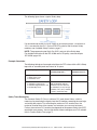
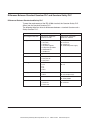
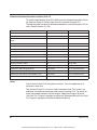
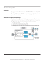
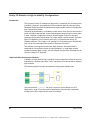
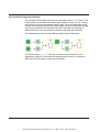
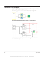
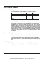
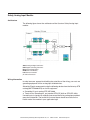
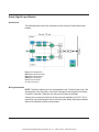

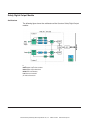
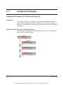
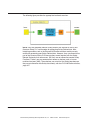
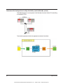
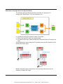
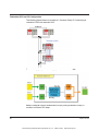

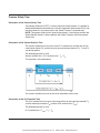
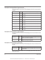
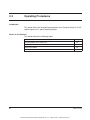
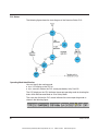


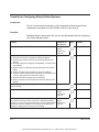
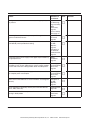
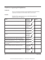
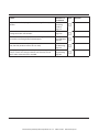
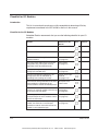
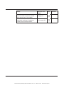
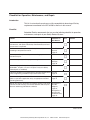
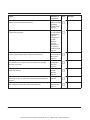


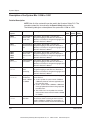
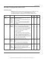
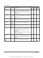
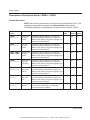
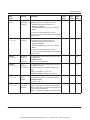
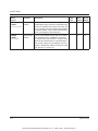
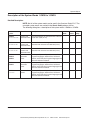
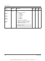
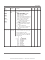
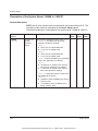
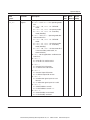
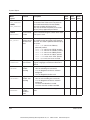
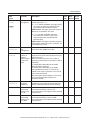
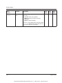
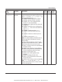
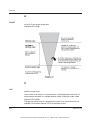


![[17] User`s Manual ver. 2.0.2](http://vs1.manualzilla.com/store/data/005765389_1-e376d351ef2708f30fcfdc5f98b9ba18-150x150.png)