1
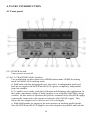
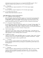
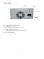
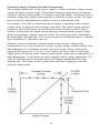
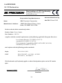
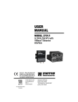
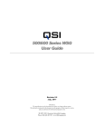
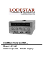
INSTRUCTION MANUAL Model LS1330 Triple Output DC Power Supply GENERAL SAFETY SUMMARY Review the following safety precautions to avoid injury and prevent damage to this product and any product connected to it. To avoid potential hazards, use this product only as specified. To avoid fire or personal injury: Use proper power cord. Use only the power cord supplied with this product or a power cord that is specified for the country of use. Ground the product: When using the supplied three prong power cord, this product is grounded through the grounding connector of the power cord. To avoid electrical shock, the grounding connector must be connected to earth ground. Before making connections to the input or output of the terminals of the product, ensure the product is properly grounded. Observe all terminal ratings: To avoid fire or shock hazard, observe all ratings and markings on the product. Consult the product manual for further ratings information before making connections to the product. Avoid exposed circuitry. Do not touch exposed connections and components when power is present. Do not operate without covers. Do not operate this product with covers and panels removed. Do not operate in an explosive atmosphere Do not operate in wet or damp conditions. Use an insulated floor material or a large, insulated floor mat to stand on and an insulated work surface on which to place equipment. Don’t expose high voltage needlessly. Remove housings and covers only when necessary. Turn off equipment while making test connections in high-voltage circuits. Discharge high-voltage capacitors after removing power. 2 Table of Content 1. Product Introduction......................................................................5 1.1 Description.......................................................................................... 5 1.2 Key Features ....................................................................................... 5 2. Specifications...................................................................................6 3. Safety Information and Installation..............................................7 3.1 Unpacking the instrument ................................................................... 7 3.2 Checking the Line Voltage.................................................................. 7 3.2 Cooling................................................................................................ 7 4. Panel Introduction..........................................................................9 4.1 Front Panel .......................................................................................... 7 4.2 Rear Panel ........................................................................................... 7 5. Operating Instructions ...................................................................11 5.1 General Precautions ............................................................................ 11 5.2 Getting Started – Independent use of the Master or Slave Supply...... 11 5.3 Typical Constant Voltage Operation................................................... 11 5.4 Typical Constant Current Operation ................................................... 11 5.5 Series Tracking Operation................................................................... 11 5.6 Parallel Tracking Operation ................................................................ 11 6. Maintenance ....................................................................................16 6.1 Fuse replacement................................................................................. 16 6.2 Line Voltage Selection........................................................................ 16 7 Service Information.........................................................................17 7.1 Warranty and Non-Warranty Service.................................................. 17 7.2 Limited 90 day Warranty .................................................................... 17 8. Appendix .........................................................................................18 8.1 CE Declaration.................................................................................... 18 3 SAFETY TERMS AND SYMBOLS These terms and symbols may appear on the product or in the user manual. ________________________________________________ WARNING: Warning statements identify condition or practices that could result in injury or loss of life. ¯¯¯¯¯¯¯¯¯¯¯¯¯¯¯¯¯¯¯¯¯¯¯¯¯¯¯¯¯¯¯¯¯¯¯¯¯¯¯¯¯¯¯¯¯¯¯¯ ________________________________________________ CAUTION: Caution statements identify conditions or practices that could result in damage to this product or other property. ¯¯¯¯¯¯¯¯¯¯¯¯¯¯¯¯¯¯¯¯¯¯¯¯¯¯¯¯¯¯¯¯¯¯¯¯¯¯¯¯¯¯¯¯¯¯¯¯ Protective Ground (Earth) Terminal 4 1. PRODUCT INTRODUCTION 1.1 Description The Lodestar Electronics Model LS1330 is a Triple Output Regulated DC Power Supply that provides one fixed output (5V/ 3A) and two variable outputs (0 – 30V/ 0 – 3A). The variable outputs can work independently, or in series tracking, or parallel mode. Four large panel-mounted LED meter displays can monitor both the output current or and output voltage of each supply. The two main channels can be operated independently or in one of two tracking modes.. In the series tracking mode the master and slave supplies are connected in series, providing a single output of 0-60V at up to 3A. In the parallel tracking mode, the two supplies are connected together in parallel, providing a single 0-30 V output at up to 6A. The voltage level of the 2 main supplies can be adjusted very precisely with the digital encoder. Both adjustable supplies support constant voltage or constant current applications. The crossover from constant voltage to constant current modes is smooth and automatic. LED’s indicate the CV (constant voltage) or CC (constant current) mode of operation. In constant voltage applications, a current limit may be preset. When load variations cause the current to reach the preset limit, the unit then regulates output current rather than output voltage. The fixed supply is ideal for powering digital logic circuitry. The 0-3 amp capacity allows the supply to be used for large circuits. Built-in overload protection automatically limits the current output to a maximum of 3 amps. An indicator lights flashes when the supply is overloaded. The output is isolated from chassis and earth ground, which permits full flexibility of connections. When needed, the (+) or (-) polarity may be strapped to ground, or either polarity may be floated to an external voltage. Additionally, the two main supplies can be used as a “split supply” with two positive voltages and a common negative, two negative voltages and a common positive, or one positive, one negative, and a common. This power supply is suitable for a variety of applications: The instrument can serve as a single or multi-voltage power source for breadboard and prototype circuits and equipment. It can provide single or simultaneously varying voltages for circuit evaluation. It can provide tracking (+) and (-) voltages for evaluating differential amplifiers. It may be used as a battery eliminator, or to power individual circuit boards or cards while removed from the system. The features and versatility of the unit, especially the triple output and tracking features, make it an ideal general purpose power supply for school laboratories and 5 home use as well as a variety of applications found in the fields of service, repair and production. 1.1 Key Features Fully featured adjustable triple output DC power supply Operates as three separate power supplies. Each power supply is completely isolated from the other two, each output can be floated and either polarity may be grounded. Two large panel mounted LED meter displays can monitor the output current (red) or output voltage(green) of the two main supplies simultaneously. Series tracking and parallel mode operation. CV/CC operation. LED indication for CV (Green)/ CC (Red) mode. Excellent regulation and low ripple characteristics. Overload and reverse polarity protection. 6 2. SPECIFICATIONS Output Voltage Display Constant Current Mode Constant Voltage Mode Output Current 0 – 30V 5V 0 – 3A 0-3A Line Regulation ≤ 0.01% + 3mV Load Regulation ≤ 0.01% + 3mV (≤ rating current) Ripple & Noise ≤ 1mVrms, 5Hz to 1MHz (current ≤ 3A) Temperature Coefficient ≤ 300 ppm/°C Recovery Time < 100µS (50% load change, minimum load 0.5A) Line Regulation ≤ 0.2% + 3mA Load Regulation ≤ 0.2% + 3mA Ripple & Noise ≤ 3mA RMS 3 digit 0.56” LED display Red LEDs for Voltage, Green LEDs for Current Accuracy Tracking (series) Fixed Output Master and Slave Supplies Fixed Output Master and Slave Supplies Fixed Output Load Regulation Ripple & Noise ≤ 0.5% of reading + 2 digits ± ≦0.5% +10 mV of master channel accuracy Unspecified ≤ 1mVrms (current ≤ 3A) 7 General: Power Requirements Operating Environment Accessories included Dimensions (W x H x D): Weight: AC 110V/220V ±10% selectable, 50/60Hz , 470W Operation: 0° to +40° C, 75% R.H. Storage: -15° to +70° C, 85% R.H AC Line Cord Instruction manual Fuse 1 set of test leads 2 Earth Ground bus straps 128 x 145 x 285 mm (5.0 x 5.7 x 11.2”) 9Kg (19.8 lbs.) Specifications and information provided are subject to change without notice. Please visit www.lodestarelectronics.com for the most current product information. 8 3. SAFETY INFORMATION AND INSTALLATION 3.1 Unpacking the Instrument The product has been fully inspected and tested before shipping from the factory. Upon receiving the instrument, immediately unpack and inspect it for any damages that might have been sustained during transportation. If any sign of damage is found, notify your local distributor immediately. 3.2 Checking the Line voltage This instrument will operate on AC 220V or 110V. Before connecting the power plug to an AC line outlet, make sure the voltage selector is set to the position corresponding to the line voltage. Note that the instrument may be damaged if it is connected to the wrong AC line voltage. __________________________________________________ WARNING .To avoid electrical shock the power cord protective grounding conductor must be connected to ground. ¯¯¯¯¯¯¯¯¯¯¯¯¯¯¯¯¯¯¯¯¯¯¯¯¯¯¯¯¯¯¯¯¯¯¯¯¯¯¯¯¯¯¯¯¯¯¯¯¯¯ Replace the required fuses according to this table. Line voltage AC 220V AC 110V Range 198V to 242V 100V to 120V Fuse T 3A, 250V T 6A, 250V ________________________________________________ WARNING:.To avoid personal injury, disconnect the power cord before removing the fuse holder. ¯¯¯¯¯¯¯¯¯¯¯¯¯¯¯¯¯¯¯¯¯¯¯¯¯¯¯¯¯¯¯¯¯¯¯¯¯¯¯¯¯¯¯¯¯¯¯ 3.2 Cooling Before applying power to the unit, make sure that the line voltage setting is correct and the ventilation holes are not blocked. Ensure that the ventilation fan is working well (it should turn on at power on condition). 9 4. PANEL INTRODUCTION 4.1 Front panel (23) POWER Switch. Turns power on and off. (13 & 14) TRACKING Mode Switches Two pushbutton switches that select INDEPendent mode, SERIES tracking mode or PARALLEL tracking mode. a) With both switches disengaged (out), the unit is in independent mode and both power supplies MASTER and SLAVE operate completely independent from one another. b) To enable series mode, push the left button and disengage the right button. In this mode, maximum voltage of both supplies is set using the MASTER voltage controls. In this mode of operation the positive terminal of the MASTER supply is internally connected to the negative terminal of the SLAVE supply. This allows the two supplies to be used as one 0-60 volt supply. c) With both buttons are engaged, the unit operates in tracking parallel mode. Now MASTER and SLAVE supplies are wired together in parallel and both the 10 maximum current and voltage are set using the MASTER controls. The 2 supplies combined can now deliver 0-to -30 volts and up to 6A. (22) “-” Terminal Negative polarity output terminal for 5V/3A fixed output supply. (21) “+” Terminal Positive polarity output terminal for 5V/3A fixed output supply. (27) 3A OVERLOAD Indicator Flashes when load current exceeds 3A MASTER Supply Controls and Indicators (9) C.C. (Constant Current) Indicator Red LED lights when the MASTER supply is in Constant Current mode. The Power Supply regulates the output current at the value set by the MASTER CURRENT control. In the Parallel Tracking mode, when this indicator is lit, both the MASTER and SLAVE supplies are in the Constant Current mode. (10) C.V. (Constant Voltage) Indicator. Green LED lights when the MASTER supply is in Constant Voltage mode. The Power Supply regulates the output voltage at the value set by the MASTER voltage. In Parallel Tracking mode, when this indicator is lit, both the MASTER and SLAVE supplies are in the Constant Voltage mode. (7) VOLTAGE Control. Adjustment of the output voltage of the MASTER supply. Also functions as adjustment control for the maximum output voltage of the SLAVE supply when either parallel or series tracking mode is selected. (8) CURRENT Control. Adjusts current limit of the MASTER supply in constant voltage mode. Adjusts constant current value of MASTER supply in constant current mode. Adjusts current for both supplies when in parallel mode (15) “+” Terminal Positive polarity output terminal for the MASTER supply. Also serves as the positive polarity terminal when operating the instrument in parallel and series tracking mode (16) GND Earth and Chassis Ground. (17) “-” Terminal Negative polarity output terminal for the MASTER supply. Also serves as the negative polarity terminal for parallel tracking mode. In series tracking operation, this terminal is internally tied to the (+) positive terminal of the SLAVE supply. 11 (3) Voltage Display Displays the voltage of the MASTER Supply (4) Current Display Displays the voltage of the MASTER Supply SLAVE Supply Controls and Indicators (11) C.V. (Constant Voltage) Indicator Green LED lights when the SLAVE supply is in the Constant Voltage mode. The Power Supply regulates the output voltage at the value set by the SLAVE VOLTAGE controls. (12) C.C. (Constant Current)/PARallel Indicator Red LED lights when the SLAVE supply is in the Constant Current mode. The Power Supply regulates the output current at the value set by the CURRENT control when in the series tracking or independent mode. Also lights when the PARALLEL tracking mode is selected. (6) VOLTAGE Control. Adjustment of the output voltage of the SLAVE supply when in INDEPendant mode. This knob is disabled in PARALLEL and SERIES tracking mode. (7) CURRENT Control Adjusts current limit of SLAVE supply in constant voltage mode. Adjusts current value of SLAVE supply in constant current mode. (18) “+” Terminal Positive polarity output terminal for the SLAVE supply. In series tracking operation, this terminal is connected to the negative terminal of the MASTER supply. (19) GND Earth and Chassis Ground. (20) “-” Terminal Negative polarity output terminal for the SLAVE supply. Also serves as the negative polarity terminal for series tracking operation. (1) Voltage Display Displays the voltage of the SLAVE Supply (2) Current Display Displays the Current of the SLAVE Supply 12 4.2 Rear Panel 27 (24) Ventilation fan, ventilation holes (25) Input voltage selector Set switch to corresponding line voltage (26) AC Power Input Connector Connect the AC power cord to this receptacle (27) Fuse Compartment 13 5. OPERATING INSTRUCTIONS 5.1 General Precautions Avoid using the power supply in ambient temperatures above +40° C. Always allow sufficient air space around the venting hole at the rear of the power supply for effective radiation to prevent internal heat build-up. Do not exceed the voltage rating of the circuit being powered. Many transistors and integrated circuits will not withstand voltage of 30 volts. 5.2 Getting Started – Independent use of the MASTER or SLAVE Supply The MASTER and SLAVE supplies each provide a 0-30V output of up to 3 Amps. This procedure covers the use of the MASTER and SLAVE supplies when used independently from one another. In the Independent operating mode, the controls of the two power supplies are completely independent and either supply can be used individually or both can be used simultaneously. Hook-up 1) Disengage all MODE switches so that the power supply is in the INDEPendent operating mode. 2) Turn off the power supply and the equipment to be powered during hook-up. 3) Connect the positive polarity of the device being powered to the red (+) terminal of the power supply. Connect the negative polarity of the device being powered to the black (-) terminal of the power supply. Note: If the negative polarity of the equipment or circuit being powered is also the chassis or common, it may be grounded to earth by strapping the black (-) terminal to the green GND terminal. Similarly, the positive polarity can be grounded by strapping the red (+) terminal to the green GND terminal. If the chassis or common of the equipment being powered is separate from both the positive and negative polarity power inputs, don’t reference the power supply’s GND terminal to either the (+) or (-) terminal. 4) Make sure that the hook-up leads offer sufficient current capability and low resistance between the power supply and the circuits being powered. 5.3 Typical Constant Voltage Operation 1) Before connecting the device to be powered to the power supply, determine the maximum safe load current for the device to be powered and set the current limit value according to the “Setting Current Limit” procedure below. 2) Set the VOLTAGE control to a minimum (fully counterclockwise). 14 3) Turn off power supply and connect it to the device to be powered (see “HookUp” procedure in this section). 4) Turn on POWER switch. The CV indicator should light. 5) Increase the VOLTAGE setting until the LED display reads the desired value. If the load current exceeds the preset current limit, the CV indicator will go off and the CC indicator will light. In this case, the power supply automatically switches to the constant current mode and further rotation of the VOLTAGE control will not increase the output voltage. Setting Current Limit 1) Determine the maximum safe current for the device to be powered. 2) Temporarily short the (+) and (-) terminals of the power supply together with a test lead. 3) Rotate the VOLTAGE control away from zero sufficiently for the C.C. indicator to light. 4) Adjust the CURRENT control for the desired current limit. Read the current value on the LED display. 5) Remove the short between the (+) and (-) terminals and hook up for constant voltage operation. The current limit (overload protection) has now been preset. Do not change the CURRENT control setting after this step. 5.4 Typical Constant Current Operation 1) Before connecting the device to be powered to the power supply, determine the maximum safe voltage to be applied and set the VOLTAGE controls to obtain that voltage reading on the LED display. 2) Determine the desired constant current value. Set the CURRENT control to minimum (fully counterclockwise). 3) Turn off the power supply and connect it to the device to be powered. 4) Turn on the power supply. 5) Increase the CURRENT control setting until the desired constant current value is read on the display, or set the current limit in advance (before connecting the load) as prescribed earlier in the “Setting Current Limit” procedure. If the load current drops below the constant current value, the CC indicator will go off and the CV indicator will light. In this case, the power supply automatically switches to the constant voltage mode, and further rotation of the CURRENT control will not increase the output current. 15 Constant Voltage/Constant Current Characteristic The working characteristic of this power supply is called a constant voltage/constant current automatic crossover type. This permits continuous transition from constant current to constant voltage modes in response to the load change. The intersection of constant voltage and constant current modes is called the crossover point. The figure below shows the relationship between this crossover point and the load. For example, if the load is such that the power supply is operating in the constant voltage mode, a regulated output voltage is provided. The output voltage remains constant as the load increases, up until the point where the preset current limit is reached. At that point, the output current becomes constant and the output voltage drops in proportion to further increases in load. The crossover point is indicated by the front panel LED indicators. The crossover point is reached when the CV indicator goes off and the CC indicator comes on. Similarly, crossover from the constant current to the constant voltage mode automatically occurs from a decrease in load. A good example of this would be seen when charging a 12-volt battery. Initially, the open circuit voltage of the power supply may be preset for 13.8 volts. A low battery will place a heavy load on the supply and it will operate in the constant current mode, which may be adjusted for a 1 amp charging rate. As the battery becomes charged, and its voltage approaches 13.8 volts, its load decreases to the point where it no longer demands the full l amp charging rate. This is the crossover point where the power supply goes into the constant voltage mode. 16 5.5 Series Tracking Operation When the series tracking mode of operation is selected, the positive (red) terminal of the SLAVE supply output is internally connected to the negative (black) terminal of the MASTER supply. This allows the power supply to be used as a single 0-60 volt power supply simply by using the negative (black) terminal of the SLAVE supply and the positive (red) terminal of the MASTER supply. In the series tracking mode, the maximum output voltage of both the MASTER and SLAVE supplies can be simultaneously varied with one control. In this mode, the output voltage (across the two supplies) is actually the sum of the voltage values of the MASTER and the SLAVE. The actual output voltage is the sum of the 2 voltages displayed, the actual output current value can read from the MASTER Display. 1) Set the power supplies to the SERIES tracking mode by engaging the left MODE button. 2) Set the SLAVE Voltage and Current controls to the fully clockwise position. The maximum current is set using the MASTER CURRENT control. Follow the instructions for “Setting Current Limit in section 5.2. 3) Adjust the output voltage to the desired level using the MASTER VOLTAGE controls. 4) Turn off the power supply and the equipment to be powered during hook-up. 5) Connect the positive polarity of the device being powered to the red (+) terminal of the MASTER power supply. Connect the negative polarity of the device being powered to the black (-) terminal of the SLAVE power supply. Turn on the Power Supply. Note: If the negative polarity of the equipment or circuit being powered is also the chassis or common, it may be grounded to earth by strapping the black (-) terminal of the SLAVE supply to the green GND terminal of the SLAVE supply. Similarly, the positive polarity can be grounded by strapping the red (+) terminal of the MASTER supply to the green terminal of the MASTER supply. If one of the supplied ground straps is to be used, use only one of these 2 configurations.. Connecting two ground straps (on Master and Slave side) could ground both the positive and negative terminals and load down the power supply, causing improper operation. If an earth ground reference is not required, or if it is not known whether the chassis is common with either the positive or negative polarity, do not reference either positive or negative terminal to the GND terminal. Make sure that the hook-up leads offer sufficient current capability and low resistance between the power supply and the circuits being powered. 17 5.6 Parallel Tracking Operation In the parallel tracking mode of operation, both supplies are strapped together in parallel. This allows for a 0-30 V supply with a 6 Amps current capability. Only the MASTER output terminals are used for parallel tracking operation. In the parallel tracking mode, the SLAVE supply output voltage and current track the MASTER supply output voltage and current. 1) Set the power supplies to the PARALLEL tracking mode by engaging both MODE buttons. The PAR LED indicator will turn on. 2) Because both Voltage and Current of the SLAVE supply track the MASTER supply, the maximum current and voltage are set using the MASTER controls, the Slave controls are disabled. Using the MASTER supply output terminals, follow the instructions for “Setting Current Limit” in section 5.3. Remember that the actual current output at the MASTER supply output terminal is the sum of the MASTER and SLAVE Current Display. 3) Adjust the output voltage to the desired level using the MASTER VOLTAGE controls. 4) Turn off the power supply and the equipment to be powered during hook-up. 5) Connect the positive polarity of the device being powered to the red (+) terminal of the MASTER power supply. Connect the negative polarity of the device being powered to the black (-) terminal of the SLAVE power supply. Turn on power supply. Note: If the negative polarity of the equipment or circuit being powered is also the chassis or common, it may be grounded to earth by strapping the black (-) terminal to the green GTND terminal (of the MASTER supply). Similarly, the positive polarity can be grounded by strapping the red (+) terminal to the green GND terminal If an earth ground reference is not required or if it is not known whether the chassis is common with either the positive or negative polarity, do not connect the Earth GND terminal to either the (+) or (-) terminal. Make sure that the hook-up leads offer sufficient current capability and low resistance between the power supply and the circuits being powered. 10-amp test leads are available as an optional accessory. 18 5.8 Fixed Power Supply The fixed power Supply provides a 5V DC output with a 3 amp current capacity. The supply is ideal for use with TTL circuits. 1) Connect the positive polarity of the device being powered to the red (+) terminal of the 5V/3A supply. Connect the negative polarity of the device being powered to the black (-) terminal of the 5V/3A supply. 2) If the red OVERLOAD indicator lights, the load placed on the supply is too high. This will cause voltage and current to drop and prevent proper operation of the supply. To correct this situation, the load on the supply must be decreased so that no more than 3 amps of current are required. Note: Either the positive or the negative terminal can be connected to the MASTER or SLAVE’s Earth GND terminal If it is not known whether the chassis is common with either the positive or negative polarity none of the 2 terminals should be connected to Earth GND. Make sure that the hook-up leads offer sufficient current capability and low resistance between the power supply and the circuits being powered. 19 6. MAINTENANCE WARNING The following instructions are for use by qualified personnel only. To avoid electrical shock, do not perform any servicing other than what’s described in the operating instructions unless you are qualified to do so. 6.1 Fuse Replacement If the fuse blows, the power lamp indicators will not light and the oscilloscope will not operate. The fuse should not normally open unless a problem has developed in the unit. Try to determine and correct the cause of the blown fuse then replace only with the correct fuse. The fuse is located in a fuse compartment which is part of the AC receptacle in the rear panel. Replace the required fuses according to this table. Line voltage AC 220V AC 110V Range 198V to 242V 100V to 120V Fuse T 3A, 250V T 6A, 250V _________________________________________________ WARNING. For continued fire protection, replace fuse only with 250V fuse of the specified type and rating, and disconnect power cord before replacing fuse ¯¯¯¯¯¯¯¯¯¯¯¯¯¯¯¯¯¯¯¯¯¯¯¯¯¯¯¯¯¯¯¯¯¯¯¯¯¯¯¯¯¯¯¯¯¯¯¯ 6.2 Line Voltage Selection To select the desired line voltage, simply set the slide switch on the rear panel to the appropriate voltage. Before you do so, unplug the unit and make sure the proper fuse is installed. 20 7 SERVICE INFORMATION 7.1 Warranty and Non-Warranty Service Please contact your local distributor for warranty and service instructions. 7.2 Limited 90 day Warranty The company warrants to the original purchaser that its products and the component parts thereof, will be free from defects in workmanship and materials for a period of 90 days from date of purchase from your local distributor. The company will, without charge, repair or replace, at its option, defective product or component parts. Please contact your local distributor for instructions. Exclusions: This warranty does not apply in the event of misuse or abuse of the product or as a result of unauthorized alterations or repairs. The warranty is void if the serial number is altered, defaced or removed. The company shall not be liable for any consequential damages, including without limitation damages resulting from loss of use. 21 8 APPENDIX 8.1 CE Declaration Declaration of CE Conformity According to EEC directives and NF EN 45014 norm Responsible Party Manufacturers Name: B&K Precision Corporation Manufacturer’s Address 22820 Savi Ranch Pkwy. Yorba Linda, CA 92887-4610 USA Alternate Manufacturing Site B&K China 1355 Declares that the below mentioned product Product Name: Power Supply Part Numbers: LS1330 complies with the essential requirements of the following applicable European Directives: Low Voltage Directive 73/23/EEC (19.02.73) amended by 93/68/EEC (22.07.93) Electromagnetic Compatibility (EMC) 89/336/EEC (03.05.88) amended by 92/68/EEC (22.07.93) and conforms with the following product standards: Safety EN 61010-1:2001 EMC EN 61326:1997 + A1:1998 + A2:2001 EN 50081-1, EN 50081-2 This Declaration of Conformity applies to above listed products place on the EU market after: January 31 2007 Date Victor Tolan President 22 [intentionally left blank] 23 Lodestar Electronics Co. www.lodestarelectronics.com Printed in China Ver. 1.0/0207 © 2007 B&K Precision Corporation 24