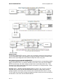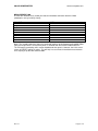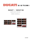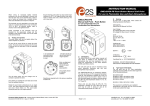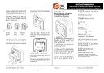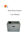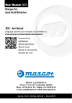
1
SOLAR POWER METER www.sunairpower.co.in SOLAR POWER METER Introduction: Solar Power Meter measures and calculates electrical parameters for Solar Installations. Features • Measures energy (Wh), charge (Ah), power (W), current (A) and voltage (V) • Accurate & precise – 0.01 A current and 0.01 V voltage resolutions • Measures peak Amps, peak Watts and voltage minimum (droop) • Rugged – handles 50 A continuous and 60 A peak at 30 V • 2.5SqMM multistrand insulated wire flying leads connect to input and output • Small & light with a tough plastic case • Acts like a wire so doesn't affect load performance. Precision Alu-Chrom current sensing resistor, with only 0.001 Ohms resistance and circuitry that draws only 17 mA • Factory calibration stores constants in EEPROM to compensate for component tolerances • Powerful, 8 MIPS micro-controller • Made in INDIA to quality standards • One-year warranty and complete user manual Specification: Parameter Range Resolution Current (A) Voltage (V) 60A* 30V 0.01 A 0.01 V Power (W) 1500W* 0.1 W Charge (Ah) 0 – 65Ah Energy (Wh) 0 – 6500Wh *Peak current only. Not rated for continuous usage. Parameter Measurement Update Period Signal Sampling Rate Data display change time In Circuit Resistance Operation Current Display Screen Nominal Operating Conditions 0.001 Ah 0.1 Wh Value 500ms 1000 samples/s ~2 seconds 0.001 Ohms 17 mA 16 Char x 2 Row 0 – 50C non condensing humidity Additional Cumulative Display Screen shows cumulated Ah and Wh up to 65535 and is stored in Non Volatile memory. After maximum cumulative count it will zero automatically. NOTE: Incorrect polarity will damage the SOLAR POWER METER. Please ensure correct polarity for connections. Keep power input leads short to ensure accurate readings. Cable cross section must be more than 3.5Sqmm to prevent self heating. All joints must be soldered or connected with air tight connectors rated for the proper current. Rev 2.1 Page 1 of 5 SOLAR POWER METER www.sunairpower.co.in SAFETY PRECAUTIONS CAUTION: High power electrical systems pose dangers independent of devices like the SOLAR POWER METER and it is the user's responsibility to be familiar with these dangers and take any necessary action to ensure safe use. Shorting a rechargeable battery or a SOLAR POWER METER connected to a rechargeable battery or battery charger can supply huge currents and have serious consequences including explosions, causing fire, damage to equipment and personal injury. Please carefully read the entire SAFTY PRECAUTIONS section to ensure safe product use. Safe Operation Limitations The SOLAR POWER METER is designed to be safe to use when operated within the parameter limits it was designed for. Typical applications are well within these limits, but it is the user's responsibility to be familiar with the SOLAR POWER METER specifications and ensure the unit is operated within its limits. Electrical Connections and Wiring There are risks associated with the potentially high currents measured by the SOLAR POWER METER. These include, but are not limited to, fire, burns and personal injury. The user must be familiar with the relevant methods, procedures and connection components before using or making any connection to the. It is suggested that any connectors and wires chosen for use be appropriately sized and rated for the intended application and attached in the manner recommended by their respective manufacturers. CAUTION: Poor connections and reckless wire handling in electrical systems may have serious consequences including personal injury, fire and property damage. Intermittent and loose connections can cause component damage! Powering Up Verify there are no exposed wires or connectors at risk for a short circuit before connecting a battery or power source to the SOLAR POWER METER. The Red “INPUT” and “OUTPUT” leads of the SOLAR POWER METER are connected to each other and the Black leads are also connected. This means the "other" side is electrically "hot" or “live” when a battery or other power source is connected to either side. CAUTION: Shorting a rechargeable battery or a SOLAR POWER METER connected to a rechargeable battery or battery charger can supply huge currents and have serious consequences including explosions, causing fire, damage to equipment and personal injury. Making Connections SOLAR POWER METER is supplied without connectors so you can use whatever kind you require. If you attach connectors to the INPUT and OUTPUT leads that mate with those you use on your units it will be easier to do testing with your SOLAR POWER METER. However, it is strongly recommended that you only use female connectors on batteries and other power sources to prevent connectors and bare metal contacts from shorting together. The user is responsible for selecting connectors rated to handle the current and voltage expected in the user’s application and to follow the instructions provided with the connectors to ensure best results. Only qualified individuals should assemble any high current connections. The Red INPUT wire goes to Positive (Plus +) battery or other device terminals and Black INPUT wire to Negative (Minus -). If you connect the Solar Power Meter without connectors, ensure the connections are airtight. Keep the wires as short as possible to prevent wire heating. Warning: Loose connections can cause component damage! Rev 2.1 Page 2 of 5 SOLAR POWER METER www.sunairpower.co.in Applying Power The SOLAR POWER METER requires a power source providing a minimum of 5.0 V to operate. This can come from a power source (battery or charger) on the INPUT/LOAD or SOURCE side. Make sure the input voltage does not exceed the rating of the meter at any time. Where Do You Connect SOLAR POWER METER The SOLAR POWER METER is essentially a direct connection between correspondingly colored INPUT and OUTPUT wires, i.e. both the “SOURCE” and “LOAD” leads of the SOLAR POWER METER are electrically “hot” when a battery or Solar Panel is connected to either side. Three connections have been shown above to describe the connections to a Charge controller, a Solar PCU and Inverter load measurement. Example use #1 – Checking Load on Inverter; Battery on INPUT side, Inverter on OUTPUT side. With the Inverter on, the SOLAR POWER METER shows the current into the Inverter, voltage and power at the battery and accumulates the Ah and Wh while the Inverter is running. This will show how much power is being consumed by the load instantly and also accumulated in the Watt Hour section of the SOLAR POWER METER. Rev 2.1 Page 3 of 5 SOLAR POWER METER www.sunairpower.co.in Example use #2 -- Battery Charging from Solar; with a Solar Charge Controller on the INPUT side and a battery bank on the OUTPUT side, the SOLAR POWER METER shows the charging current into the battery, the voltage and charging power at the battery and accumulates the charge (Ah) and energy (Wh) into the battery. Note that for a Solar PCU the charge controller is inside and therefore, the SOLAR POWER METER will need to be connected between the Solar Panel and the Solar input to the Solar PCU Battery Charging You can monitor the current, accumulated charge and energy into and voltage on a battery undergoing charging. Connect the SOLAR POWER METER as shown in the "Charge Controller or Solar PCU to Battery" connection diagram shown above. Make sure the connections are firm and airtight and keep the lengths of the wires to a minimum to avoid power loss. If the wires get warm or hot, use a thicker wire or double the wires to get a higher cross section. Note that the SOLAR POWER METER Peak Amps, Peak Watts and Voltage Minimum values are cleared whenever the SOLAR POWER METER turns on. If the battery is connected before the charger is turned on, the SOLAR POWER METER will track the minimum voltage on the battery during the charging process. With the charger on and the battery charging, the SOLAR POWER METER displays the ongoing charging electrical values. The current (As) and power (W) show the average rate of charge and the voltage indicates the current battery charging voltage. At the end of the charge the SOLAR POWER METER Data display indicates the total charge (Ah) and energy (Wh) the battery received as well as the peak Amps (Ap) and peak Watts (Wp) used and the minimum voltage on the battery during the charging process. Make a note of these final values as they can be used to determine charger efficiency Battery Discharging, Efficiency and Health When discharging a battery bank through the SOLAR POWER METER into a load you can monitor key battery parameters like actual available charge and energy, peak and average current and battery voltage. Connect the SOLAR POWER METER as shown in the "Load measurement from inverter output" connection diagram. The load device you connect on the LOAD side must be capable of handling the discharge power the battery bank or inverter can provide. Example loads include, light bulbs, appliances and electronics. The SOLAR POWER METER requires at least 5.0 V to continue working so if the battery discharges below this, the SOLAR POWER METER will reset and not show any readings. After connecting the OUTPUT to the SOLAR POWER METER, connect the battery to the INPUT. Discharging begins when the battery is connected and the inverter is turned ON. When the battery is discharged, the SOLAR POWER METER display indicates the total charge (Ah) and energy (Wh) the battery delivered to the load as well as the peak Amps (Ap) and peak Watts (Wp) used and the minimum voltage on the battery during the discharging process. Make a note of these final discharge values to determine charger efficiency, battery capacity and health. Battery Health Battery Health is determined by comparing the actual energy or charge capacity with the manufacturer's specifications or a "new" battery as a reference. Since it can be difficult to get manufacturer specifications to match test results, it is often simpler and just as useful to record the capacity value of a "new" battery and save that as a baseline. Note that a "new" battery may be defective and give out of specification results. By occasionally discharging a battery bank and comparing the energy delivered to the baseline value delivered when it was first put into service, you can track that battery's health. The percentage of baseline capacity at which a battery is considered to be at the end of its life depends on battery chemistry and how it is used. A reduction in charge capacity can also be an indication of battery pack damage or imminent failure. To summarize, the percentage of baseline or initial capacity indicates a battery's health. Baseline Capacity Ratio = Current Capacity Original Capacity Rev 2.1 Page 4 of 5 SOLAR POWER METER www.sunairpower.co.in MEASUREMENT LOG Use the form below to easily record your data for immediate and future reference. Make photocopies so they're always handy. PROJECT: DESCRIPTION Amps Volts Watts Ah Wh Ap Vm Wp DATE VALUES RECORDED Note: The second screen that shows the cumulated readings for Ah [Ampere hour] and Wh [Watt hour] will not get RESET to Zero when power is removed from the SOLAR POWER METER. This will keep accumulating until it reaches 999999 and then go to 0. However, the initial screen values will RESET to 0 for all values. This will help in assessment of intermittent measurements for a capacity of up to 64Ah and 6553.6Wh. Rev 2.1 Page 5 of 5