1
Solar Home System
User Manual
This manual aims at explaining the function, installation and using method,
maintenance of the 50 W solar systems. In order to connect all the parts of
the system safely, such as: Solar module, power box, battery, charge
controller and DC saving fluorescent lamp etc. Please read and understand
this manual detailedly and then start installing. Moreover, while installing, users
must install gradually according to the description of the manual strictly.
1. Safety Instructions
1.1 Refer installation and servicing to qualified service personnel. High
voltage is present inside unit. Incorrect installation or use may result in
risk of electric shock or fire. No user serviceable parts in this unit.
1.2 Remove all sources of power, photovoltaic and battery before servicing
or installing.
1.3 WARNING - RISK OF EXPLOSIVE GASES
a) Working in the vicinity of lead-acid batteries is dangerous. Batteries produce explosive
gasses during normal battery operation.
b) To reduce risk of battery explosion, follow these instructions and those published by
battery manufacturer and manufacturer of any equipment you intend to use in vicinity of
battery.
1.4 PERSONAL PRECAUTIONS
a) Someone should be within range of your voice or close enough to come to your aid when
you work near a lead acid battery.
b) Have plenty of fresh water and soap nearby in case battery acid contacts skin, clothing
or eyes.
c) Wear complete eye protection and clothing protection. Avoid touching eyes while working
near battery.
d) If battery acid contacts skin or clothing, wash immediately with soap and water. If acid
enters eye, immediately flood eye with running cold water for at least 10 minutes and get
medical attention immediately.
e) NEVER smoke or allow a spark or flame in vicinity of battery.
f) Be extra cautious to reduce risk of dropping metal tool onto battery. It might spark or
short circuit battery or other electrical part that may cause explosion.
g) Remove personal metal items such as rings, bracelets, necklaces, and watches when
working with a lead-acid battery. A lead-acid battery can produce a short circuit current
high enough to weld a ring or the like to metal, causing a severe burn.
1.5 PREPARING TO CHARGE
a) Never charge a frozen battery.
b) Be sure battery is mounted in a well ventilated compartment.
1.6 CHARGER LOCATION & INSTALLATION
a) Controller employs components that tend to produce arcs or sparks. NEVER install in
battery compartment or in the presence of explosive gases.
b) Protect all wiring from physical damage, vibration and excessive heat.
c) Insure that the controller is properly setup for the battery being charged.
d) Do not expose controller to rain or snow.
e) Insure all terminating connections are clean and tight to prevent arcing and overheating.
f) Charging system must be properly installed as described in these instructions prior to
operation.
g) Do not connect to a PV array capable of producing greater than 24 amps of short circuit
current @ 25 °C.
1.7 Use the scope
This SHS050 is applicable to the family usually power supply, such as the saving lamp, the
direct current radio the small power of etc. solar cell outside, other equipments( such as:
Power box, battery) under the condition of have no protection measure, can install only
indoors.
2. Specifications
2.1 General Specifications
Product name: FS-SHS50W
Product Description: Solar Home System
Products list of the solar home system
Item
Name
specification
QTY
1
Solar Module (50Wp±5%)
18V,50Wp
1
2
Solar Panel Mounting Frame (Pole)
2.5m
1
3
Battery (Sealed Lead Acid)
12V/65Ah
1
4
5
6
7
8
9
Battery and Power supply box
Charge Controller for Solar PV
Compact Fluorescent Lamps (CFL)
Cable of Lamp
Cable of solar module
User Manual
430*220*320mm
12V/6A
12V/11W
5m*2.5mm2
15m*2.5mm2
1
1
1
1
1
1
2.2
Solar Charge Controller CA06-2
Please read the charge controller manual carefully taking special note of the safety and
Usage recommendations at the end. The manual gives important recommendations for
installing, using and programming as well as a troubleshooting guide for potential
problems with the controller.
WARNING :Do not use over 72W loads forever.
It is a new CA controller; you will own a state-of-the art device which was developed according to the latest
available technical standards. It comes with a number of outstanding features, such as:
z
3 LEDs for a clear, readable display of the state of charge
2
z
16 mm connector clamps
z
Temperature compensation
z
Electronic protection without fuses
This manual gives important recommendations for installing, using and configuration as well as remedies in
case of problems with the controller. Read it carefully in your own interest. Please take note of the safety
and usage recommendations at the end of this manual.
Description of Functions
z
The charge controller protects the battery from being overcharged by the solar array and from being
deeply discharged by the loads. The charging takes place through multiple stages which include
automatic adaptation to the ambient temperature for optimal charging of the battery.
z
The controller is intended for use at 12 V system voltages.
z
The charge controller has a number of safety and display functions.
Mounting and Connecting
The controller is intended for indoor use only. Protect it from direct sunlight and place it in a dry
environment. Never install it in humid rooms (like bathrooms).
The controller measures the ambient temperature to determine the charging voltage. Controller and battery
must be installed in the same room.
The controller warms up during operation, and should therefore be installed on a non flammable surface only.
REMARK: Connect the controller by following the steps described below
to avoid installation faults.
When mounting the controller with screws, make sure
to use screws that suit the attachment material
(use screws with 4 mm shaft and max. 8 mm head
diameter, no counter sunk). Keep in mind that the
screws also have to carry the force applied by the
wiring.
Make sure that the ventilator slits on the sides
are unobstructed.
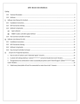
A DIN Rail mounting plate is available as an accessory (CX-DR2). This
allows mounting the controller on a standard 35mm DIN rail. Place the
controller on the mounting plate, and use the screws supplied with the
mounting plate to fix it to the controller.
Connect the wires leading to the battery with
correct polarity. To avoid any voltage on the
wires, first connect the controller, then the
battery. Keep in mind the recommended wire length
(min. 30 to max approx. 100 cm) and the wire size:
2
CA06-2: min. 2.5 mm
WARNING: If the battery is connected with reverse polarity, the charge
controller will also give the wrong polarity on the load terminals.
Never connect loads in this situation!
Connect the wires leading to the solar array with
correct polarity. To avoid any voltage on the
wires, first connect the controller, then the solar
array. Keep in mind the recommended wire size:
2
CA06-2: min. 2.5 mm
REMARK: place positive and negative wires leading to the solar
generator close to each other to minimize electromagnetic effects.
Connect the wires leading to the loads with correct
polarity. To avoid any voltage on the wires, first
connect the wire to the load, then to the
controller. Keep in mind the recommended wire size:
2
CA06-2: min. 2.5 mm
Starting up the Controller
System Voltage
The controller is intended for use at 12 V system voltage.
Battery Type
The controller does not generate an equalization charge, and is therefore suitable for use with lead acid
batteries with liquid electrolyte (vented battery) and lead acid batteries with solid electrolyte ('gel' or
'fleece' type).
Recommendations for Use
The controller warms up slightly during normal operation.
The controller does not need any maintenance or service. Remove dust with a dry tissue.
It is important that the battery gets fully charged frequently (at least monthly). Otherwise the battery
will be permanently damaged.
A battery can only be fully charged if not too much energy is drawn during charging. Keep that in mind,
especially if you install additional loads.
Display Functions in normal operation
The controller is equipped with 3 LEDs for display of the operating status.
Charge display
Battery voltage display
Load status display
In normal operation mode, the controller displays the charging status, the status of battery voltage and the
status of the load output.
Charge display
Solar array does not supply
electricity
(LED off)
Battery voltage display
Battery voltage>12V
(LED off)
Solar array does supply
electricity
(LED on)
Battery voltage<12V
(LED on)
Battery voltage<11.7V
(LED flashing)
When the battery voltage is indicated as low, it is recommended to use the remaining energy economically.
The charge controller will subsequently switch off the load.
Load status display
In case of deep discharge or overload/short-circuit, the load output is switched off. This is indicated by:
Overload or Short-circuit
Low voltage
of load (LED flashing)
disconnect
(LED on)
Low Voltage Disconnect Function (LVD)
The controller is equipped with a low voltage disconnection function to protect the battery against a deep
discharge: This function is controlled by the voltage, and automatically switches off the load output at a
battery voltage lower than 11.5 V.
Normal operation
(LED off)
As soon as the battery reaches a voltage of 12.5V the load output is switched on again.
Safety Features
The controller is protected against wrong installation or use:
At the solar
At the solar terminal
terminal
Battery
Unrestricted
connected with
.
correct polarity
At the load
terminal
Normal operation
Unrestricted
Unrestricted
Yes, if only the
battery is connected.
Unrestricted
Reverse polarity Unrestricted
Yes, if only the
battery is connected.
Load output is
protected. Loads
might be damaged.
Battery
connected with
wrong polarity
Short circuit
Unrestricted
Unrestricted CAUTION: Battery must
be protected by fuse.
Unrestricted
Over current
No
protection
--------
Controller
switches off.
No connection
Unrestricted
Unrestricted
Unrestricted
Reverse Current Unrestricted
--------
--------
Over voltage
Varistor 56
V, 2.3 J
Max. 30 V
No protection
Under voltage
Normal
operation
Controller switches
off load terminal.
Controller
switches off load
terminal.
WARNING: The combination of different error conditions may cause
damage to the controller. Always remove an error before you continue
connecting the controller!
Error Description
Error
Display
Reason
Remedy
Load will reconnect
Battery is low
as soon as battery is
(LED on)
recharged.
Loads are not
supplied
Switch off all loads.
Overcurrent/ Remove short circuit.
Short circuit
Controller will
switch on load
of loads
(LED flashing) automatically after
max 1 minute.
Battery is
empty again
after a short
time
Battery has low
capacity
(LED on)
Change battery
Battery is not
being charged
during the day
Solar array
faulty or wrong
polarity
(LED off)
Remove faulty
connection/reverse
polarity
General Safety and Usage Recommendations
Intended Use
The charge controller is intended exclusively for use in photovoltaic systems with 12 V nominal voltage, and
in conjunction with vented or sealed (VRLA) lead acid batteries only.
Safety Recommendations
z
Batteries store a large amount of energy. Never short circuit a battery under any circumstances. We
recommend connecting a fuse (slow acting type) directly to the battery.
z
Batteries can produce flammable gases. Avoid making sparks, using fire or any naked flame under any
circumstances. Make sure that the battery room is ventilated.
z
Avoid touching or short circuiting wires or terminals. Be aware that the voltages on specific
terminals or wires can be up to double the battery voltage. Use isolated tools, stand on dry ground
and keep your hands dry.
z
Keep children away from batteries and the charge controller.
z
Please observe the safety recommendations of the battery manufacturer. If in doubt, consult your
dealer or installer.
Liability Exclusion
The manufacturer shall not be liable for damages, especially on the battery, caused by use other than as
intended or as mentioned in this manual or if the recommendations of the battery manufacturer are neglected.
The manufacturer shall not be liable if there has been service or repair carried out by any unauthorized
person,
Mounting and Connecting Mounting and Connecting
Nominal voltage
Boost voltage
Float voltage
Load disconnect voltage
Load reconnect voltage
Temperature compensation
Max. solar panel current
Max. load current
Dimensions
Weight
Max. wire size
12 V
14.5 V
13.7 V (25°C)
11.5 V voltage controlled (25°C)
12.5 V
-4 mV/cell*K
CA06-2: 6 A
at 50°C ambient temperature
CA06-2: 6 A
at 50°C ambient temperature
81 x 100 x 37 mm (w x h x d)
180 grms
2
16 mm (AWG #6)
Nominal voltage
Self consumption
Ambient temperature range
Case protection
12 V
<4 mA
-40 to + 50 °C
IP 22
2.3 Electrical Box
Model
System Voltage
Charge controller
Battery
Module Power
FS-SHS50W
12V
12V、6A
12V、65Ah
50Wp
PV Input
1
12VDC Output
3
9VDC Output
1
Switch
3
2.4 Solar Module
Solar module is a device that converts radio technology to DC electricity. Each
module is made of 36 pieces cells. Normally, the design life of solar module is
more than 20 years. We adopt FS-PV50W solar module in this system, the
main parameter is as follows:
Standard condition:(AM1.5)Radiant intensity=1000W/m2,Temperature=25℃
Working Temperature
Peak power
50℃
50W±5%
Tem. coefficient of short circuit
2.0mA/℃
Open-circuit Voltage
21.6V±5%
Tem. coefficient of open circuit
-78mV/℃
Max Voltage
17.2V±5%
Short circuit current
3.3A±5%
Filling gene
70%
Windward pressure
2400Pa
Max current
2.9A±5%
Insulated Voltage
≥600V
Weight
6Kg
Installing aperture
Φ5.5
Exterior dimension
807×519×35
2.5 Battery
Battery is the energy storing device. The batteries we adopt is maintenance-free lead
acid battery. The character is high reliability, long life and so on. In addition, the
following is also its character:
Maintenance-free;
Wide working temperature(-35~45℃);
Long using life;
Blast proof
Small inner resistance;
Small self discharging;
The main parameter is as follow
Model
12V65Ah
Dimension(mm)
Rated
Capacity
Voltage(V)
(Ah)
Weight
Length
Width
Height
12
65.0
350
166
179
(Kg)
21
2.6 Cable
The function of cable is to connect all the parts of this system together. The
working temperature of the cable is -20~+50℃. It includes:
Cable of PV Solar
Cable of Lamp
PV module to controller
2.5mm²
15m
Controller to battery
2.5mm²
0.35m
Controller to lamps
1.5mm²
5M
2.7 Energy-saving Lamp
Model
12V11W
Rated Power
11W
Rated Voltage
12V
Rated Current
650mA
Rated Lum
550Lm(50Lm/W)
2.8 Bracket
The function of bracket is supporting solar modules. It is made of galvanization steel
tube which the diameter is 48mm.The thickness is 1.5mm, the length is 2.5m. Bracket
includes tray and pole.
3. Principle of Operation
Exposing the solar module to sunlight directly, the solar module can transform the
sunlight to
electricity and store it in the battery trough charge controller. The electricity then
can be supplied to 12V loads, such as DC compact fluorescent lamp and DC TV,
through controller.
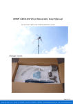
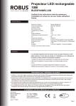
4. Diagram of PV Control
1. Load Status Indicator
2. Battery Status Indicator
3. Charging Indicator
4. Solar Charge Controller
5.9V Load Output
6.7.8. DC load Switch
9. Load - DC Compact Fluorescent Lamp
10. Load – DC VCD
11. Load - DC TV
12. Solar PV Panel
13. Battery
5. Specification of Electrical Box
6. Installation of SHS050
After disconnecting the packing, please read this manual carefully and
operate the system according to the instruction. It is good for extending
the life of equipment, especially the battery. At the same time,
it can also lessen some unnecessary loss.
6.1 Check the equipments and accessories
1) Check and amount all the accessories of FS-SHS50W to confirm
whether they are all right. (Refer to the products list)
2) Whether all the accessories are in good condition. In the
transportation there may be some broken components, If these
components are used in the system, it may affect the system.
6.2 Installation and connection of system
6.2.1 Installation of bracket and solar panels
Bracket is made up of two parts: pole and tray.
Installing step:
1) Tamp the pole into the ground
2) Insert the tray on the top of pole and rivet it with screw.
3) Rivet the panel on the bracket with screw.
Attention:
● The azimuth angle of the bracket bottom should be just south. The obliquity of the
solar module is 60° ;( in accordance with local latitude)
● Because of the heavy wind, each junction should be connected hard.
● It is not allowed to sustain other objects with the bracket. It is also not allowed to
climb the bracket.
6.2.2 Placement of power box
Except for the special protector, it is not allowed to put the power box
outside.
Attention:
● It is not allowed to put power box in the environment with combustible gas;
● Power box must be put in dry environment;
● It should be put far away from water;
● be sure that animals and children can not touch it;
● It should be taken and put slowly;
● In order to watch the condition of system, power box should be put in the place
where is easy to watch;
● In order to connect other accessories (solar panels, battery, DC lamps, TV set and
so on), power box should be put in a moderate position.
● Be more careful when install and transport the batteries.
● If the storage period of battery exceed 6 months, it should be charging maintained.
The storing place should be dry, clean and ventilate.
6.2.3 Connect solar to power box
!Before connecting the cable, please confirm that the load switch of power box is
located in “OFF/0N” position.!
It is strictly not allowed to connect positive and navigate
of solar module in reverse;
!After connection, cable should be put in the place where is not easy to touch.
Please confirm the distance from solar bracket to power box. The length of cable is
15 meters. We use 2.5mm2×15m cable to connect solar module to power box. First
open the junction box at the back of solar module, and then insert it in the hole.
After connected two cables, screw down the waterproof connection and cover the
junction box.
Attention:
● While connecting, cover the solar module of put it in a poor light;
● There may be spark when connecting, users must be careful!
● Cable can be an aerial cable. If it is put under the ground, it should be put into a
protecting cannula.
6.2.4 Connect load to the power box
At the faceplate of power box, there are three 12VDC lamps or DC TV
output port and one 9VDC radiogram output port. Connect DC lamps or DC
TV and radiogram to the corresponding socket. The length of cable is 6
meters, please consider best putting position.
After the above steps, the installation of SHS-50 has been finished.
7. Operating method of FS-SHS050
SHS-50 is the system which can be used easily. Power box is the core
of the system. Because that charge controller, battery, switch and all the
ports are installed in the box.
7.1 Charge for battery
After confirming the veracity of the system installation, connect the solar cable to
the relevant socket on the power box, then it can charge for battery. At this time,
the green LED indicator of charge controller is lightening. This cable can be
connected with power box all the time.
8. Maintenance
The FS-SHS050 has no movable parts, not easy damage, it support also
very simple, but periodical maintenance also is must of, otherwise may
affect the normal usage, even shorten the service life.
8.1 When the solar PV module obliquity over 60 degrees, all dusts can
be sweep by the rain water flush but, however compare in the sandstorm big
and rarely seen region of rain water, should usually the clearance dust, keep
the solar PV module surface of clean, in order to prevent the influence
generates electricity the quantity. Sweep can wipe to the dust, had better
flush with the clear water, and then wipe the stem with the clean dish cloth.
Attention:
Wipe to try with the causticity melting agent or hard things absolutely not to.
8.2 Periodically check the tight and solid degree of all gearing parts, in order
to prevent was knocking down by the breeze or the animal dint outside etc.
8.3 Meet the excrescent weather of hail, strong breeze, rain-storm...etc.,
should adopt the protection measure in time.
8.4 Usually check the storage battery to refresh to turn on electricity the
circumstance, at any time observe the electrode or connect whether line
decay or get in touch with the bad place or not.
8.5 The detection contain excrescent circumstance should check,
maintain immediately.
9. Malfunction the analysis
Please read the charge controller manual